MCD Racing duox User manual

INSTRUCTION MANUAL
LARGE SCALE TOURING CAR
1
You can download the most up to date exploded views on our website.
Please go to: www.mcdracing.com/support , select Exploded View from
the Type Menu and hit the search button to see all the exploded views.
Thank You.
Thank you for purchasing MCD. Reliability and ease of maintenance are the two key
qualities of our products. When we design our cars our primary goal is always to ensure
our customers the best driving experience possible.
Welcome to the TEAM MCD.
Contents
Warranty and Safety Precautions
Fuel Safety Precautions
Make sure your car is properly maintained before you start running!
Operation
Needed Equipment
Mounting the Engine
Gear Ratios
Air Booster
Air Booster Assembly
Servo Installation
Installing the Throttle & Rear Brake Linkage
Installing the Front Brake Linkage
Setting the Brakes
Installing the Steering Servos
Shock Maintenance
Toe Setting
Hydraulic Dierential
Hydraulic Dierential Set-up
2
2
3
3
3
4
4
5
5
6
6
7
7
8
9
9
10
10
2
Never breathe the exhaust fumes as they are poisonous. Never operate the engine in closed spaces.
If someone is exposed to the exhaust fumes, the person has to be taken out to open air in case of nausea.
Always store your fuel in a sealed container specifically made for gasoline.
Quick Guide for MCD Racing Cars
Warranty and safety precautions
With the purchase of this MCD 1:5 car, your car is under two year warranty starting with the date of purchase. This warranty
covers any material or manufacturing faults that might be present at the date of purchase.
This warranty does not cover:
Ordinary wear and tear.
Wearable parts like the clutch or gears.
Damages as a result of misuse by the driver.
Damages from wrong maintenance procedures .
Cosmetic damage.
Please consult your local hobby shop first in case of a warranty claim.
In case you decide to send this product for repair, please attach a proof of purchase. Before you send
your product to your dealer, we recommend you to consult them first (either via telephone or email)
The sender has to pay for shipping costs. Every warranty claim has to be validated by service department
first. Dismissed claims are subject to administrative fees (checking and handling) before we send the items
back. Repairs that are not covered by warranty have to be paid for in advance. MCD Racing cannot be held
responsible for any damages that emerge from or are caused by, directly nor indirect use or misuse of this
product or its accessories.
This product should not be considered as a toy and therefore not suitable for children under the age of 14. The engine
must not be operated interiors.
IMPORTANT:
Advise your local hobby shop before you first start up the engine, especially considering proper operation
and safety precautions. If possible, get a demonstration on how to operate the engine, and make yourself
familiar with it.
Only if and when you fully understand its operation, you should start using the engine. Always be sure to
operate within the safety guidelines indicated below to avoid damages or personal injury. Never try to
modify any part of the engine as this voids the warranty and may lead to damages or personal injury.
Fuel – Safety precautions
Use only minimum 95 Octane gasoline mixed with high quality two-cycle engine oil. Use a 20:1 ratio gasoline to oil.
(e.g. 250ml oil mixed with 5lt Fuel)
Stay away from open fires while fuelling or running the engine. Do not smoke nearby!
Store the fuel in a well ventilated area, away from heat sources, fire or batteries.
Always keep the fuel in a clearly marked container away from the reach of children.
In case of eye contact, rinse thoroughly with warm water.
In case of skin contact, rinse thoroughly with warm water and soap. Do not scrub.
Never handle the engine or the exhaust until they are cooled down. These parts can get up to 170°C when
operating.

3
Needlenose Pliers PH 2
95 or Higher
Octane Gasoline
2 Stroke Oil
(High Quality racing
oil recommended)
Cutter
Divider
Caliper
Engine
Receiver
Battery extension wire
At least 4 Servos
(Minimum capacity: 15kg for
steering, 15kg for throttle and
brake)
Or
Needed Equipment
Transmitter
Sizes: 5.5mm, 7mm, 9mm, 13mm Sizes: 1.5mm, 2mm, 2.5mm, 3mm, 4mm
Wrench
Hex Driver
NiMH Battery
(Max dimensions:
127mm x 57mm x h:39mm)
Battery Charger
Li-PO/LiFE Battery
(Max dimensions:
127mm x 57mm x h:39mm)
Screwdriver
Air Filter Oil Thread Lock
Shock Oil
(standart 1000cSt)
Brake Fluid
(silicone dot 5)
Hydraulic Oil 32
inside the Di
Body Reamer
Make sure your car is properly maintained before you start running!
Check all screws and nuts for a proper and firm seat. Use thread lock, where screws thread into metal.
Never drive without fully charging batteries for the transmitter and receiver against the risk of a runaway.
Always check the brake and throttle linkage before you start the engine.
Be sure the air filter is clean and properly oiled. Never run the engine without an air filter as dust
and debris may enter inside and seriously damage the engine.
Always be sure that nobody else uses the same frequency.
Always be sure that there is grease inside the cup joint boots.
Operation
Exhaust fumes are poisonous. Never operate the engine in closed spaces.
Break-in procedure should be payed attention.
Be sure the air filter is clean and well-oiled. Never operate the engine without an air filter attached.
Use minimum 95 Octane gasoline mixed with high quality two-cycle engine oil.
Use a 20:1 ratio gasoline to oil. (e.g. 250ml oil mixed with 5lt Fuel)
Use original engine spare parts only.
Check the air filter regularly for eventual damages.
The Do’s The Dont’s
Switch on the transmitter before starting the
engine.
Never run with low batteries.
Drive carefully when there are people around. Never run your car in wet conditions or on tall grass.
Switch engine o first, and then the transmitter. Never use chemicals for cleaning your car.
Always check the condition of the batteries before
running the engine.
Never run your car without the bodyshell.

4
Mounting the Engine
Gear Ratios
Default Ratio:
Shims can dier according to the clutch
Engine
39
38
37
36
35
62
63
64
65
66
23
23
23
23
23
73
73
73
73
73
5,05
5,26
5,49
5,73
5,99
Center/
Engine
Center/
Di.
Di. Final Ratio

5
Caution!
Air Booster
Air booster assembly
Do not use the air booster without oiling.
Dust and particle can damage the engine.
APPLY FOAM FILTER OIL!

6
Servo Installation
Installing the throttle & rear brake linkage
10. Hold full throttle on the transmitter then increase throttle
EPA slowly until there is 0,2mm gap left between the
parts shown in Figure F.
11. After this setting leave the throttle to neutral position.
12. The throttle linkage is assembled and alignment is done. Check if the linkage is functioning properly.
1. Turn on your radio.
2. Check if servos are functioning.
3. Be sure the servo turns on correct direction. (Throttle direction: CCW,
Brake direction: CW. Reverse if direction is not correct!)
4. Make sure you adjust neutral position as shown in Figure A.
If necessary correct the neutral position from the sub trim menu on
your transmitter.
5. After completing the previous steps install the throttle and rear brake
linkage on the servo horn as indicated in Figure B.
6. Install the linkage on the rear brake as shown in Figure C.
7. Install the linkage on the carburator. (Figure D)
1. Mount the servos on the servo tray from below as shown on
Figure A.
2. Install the front brake servo horn parallel as shown.
3. Install the steering servos with a slight angle as shown.
The definitive angles will be determined during the steering
installation phase (explained on page 8).
4. Connect the steering servos with a Y cable.
5. Install the rear brake servo horn parallel as shown.
6. Connect the servos to the receiver as indicated
on Figure A.
7. Mix the 3rd and 2nd channel. (Check your radio
booklet for information)
8. Reduce the throttle end point adjustment(EPA) around 50%
from the transmitter.
9. Apply full throttle from the trigger. (Figure E)
Figure C
Figure F
Leave a 0,2 mm gap while on full throttle(12)
Figure E
Figure D
Screw from here
Rear Brake
Receiver
3
2
1
B
Figure A
Servo Tray
Throttle & Rear Brake
Servo horn parallel
Channel 2
Front Brake
Servo horn parallel
Channel 3
Steering
Servo horns with slight angle
Channel 1
Connect with a Y cable
Figure B
Install the throttle & rear brake linkage on the horn.
7
Important!
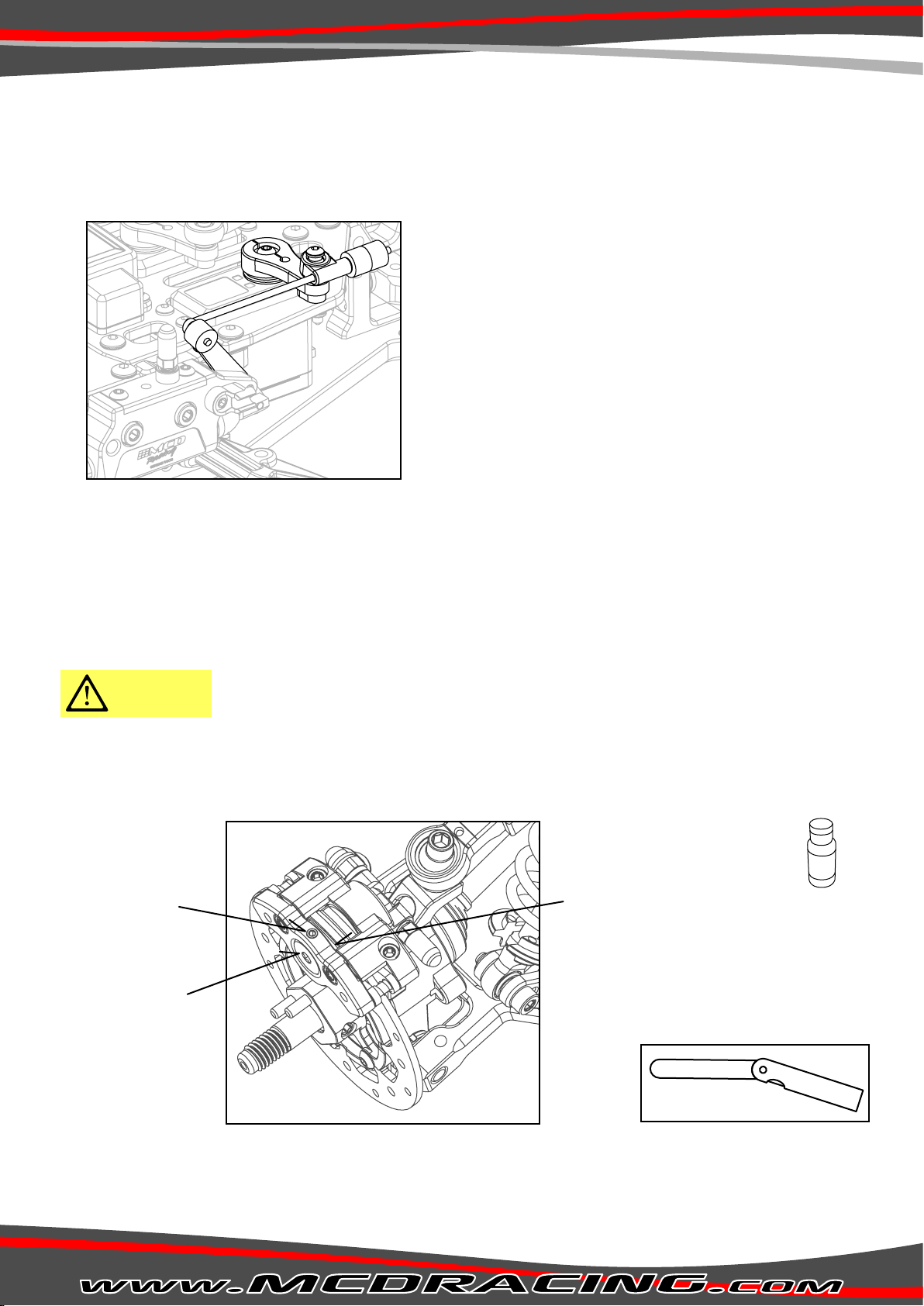
Installing the front brake linkage
Setting the brakes
During operation the brake pads wear over time causing weakening of the brakes.
In order to compensate wear over time unscrew the set-screw and insert a 2mm feeler gauge in between the brake pad
and the disc. Adjust the gap with a 3mm hex screw.
Insert a 2mm a feeler gauge.
Unscrew.
Adjust the gap with a
3mm hex screw.
1. Set the servo horn position parallel as shown in Figure A.
2. Connect the front brake linkage to the servo horn as shown in Figure G.
Figure G
1. After the linkages are installed, switch on your radio and reduce the brake end point from the transmitter EPA menu to 30%.
2. Apply full brake from the trigger and hold.
3. By moving the car back and forth with your hand, start slightly increasing EPA to approx. 50% untill the brakes lock.
4. If it doesn’t lock at 50% turn back to the step 1 and re-adjust until it locks at 50%.
Feeler gauge.
0.2 mm
Brake Fluid
(silicone dot 5)

8
Insert a 4 mm round pin and lock the
ackerman plate to prevent steering.
Servo connection holes Figure I
Figure J
Figure H
1. Install servos as shown in Figure A.
2. Insert a 4 mm round pin and lock the Ackerman plate to prevent steering (shown in Figure I). Servo saver will be
locked in the central position.
3. Make sure you install the steering servo horns with a slight angle as shown on Figure A.
4. Mount the steering servo linkages to the correct servo holes according to your servo horns(by default the linkages
are mounted on the outer servo holes). Figure H
5. Be sure that the distance D is equal to the servo horn distance E as shown in Figure I.
6. Measure the distance A shown in Figure I with a divider.
7. Set the servo linkages the same distance with distance A.
8. Set steering EPA to approx. %70.
9. From the sub trim menu, adjust the servo horns positions to match the previously adjusted servo linkage lengths.
10. Assemble the linkages on the servo horns.
11. Remove the 4mm round pin inserted in step 2.
12. To set the steering endpoint(EPA), open the EPA menu. Steer until the steering bracket touches to the wishbone
tower(shown in Figure J) and set your EPA. Do the same step for both left and right.
Double-servo installation is critical and should be handled carefully. If not installed
properly the servos will work against each other and damage themselves.
Be sure that the distances A, B and C are equal!
Instaling the steering servos.
Caution!
Tip!: Use a divider to
measure the distances.
C
AA
D
D
E
E
B
Servo 1 Servo 2
Front
Rear
Be sure that the steering servo
connection hub is oriented correctly.
Steer until the steering bracket touches to the wishbone tower.
Caution!

9
of the shock body.
- Stroke the shaft up&down approx
- Apply thread lock.
Apply thread lock.
8mm from the top of the shock
at the bottom.
- Remove the screw.
comes out.
- Set the screw.
4
10
Toe Setting
Shock Maintenance
Toe-in:
Mount the toe inserts pointing the direction that the hubs will be installed
(L or R) as shown beside.
e.g. If the hub will be installed on the left side, the inserts should be pointing L
for toe-in.
Toe-out:
Though not used frequently if toe-out is desired in the rear, simply swap left
and right hubs. You will obtain same amount of toe-out.
The toe angle can be changed by replacing the inserts with the desired angle.
The degree which defines the toe-angle can be noticed by the sign on the
inserts as indicated in the figure below.
Hub
Toe inserts angles:
Toe inserts pointing left for left side.
1° 1,5° 2,5°2° 3°
Shock Oil
(standart 1000cSt)

10
Hydraulic Di Set-Up
Hydraulic Dierential
Adjusting screw
Lock or unlock the hydraulic di with the adjusting screw. Loosen the screw for slipping, tighten for locking.
Important!
Maintain dierential every 20 tanks.
The hydraulic di contains pressured oil.
Do not fully open the di.
Caution!
Hydraulic Oil 32
inside the Di

Table of contents
Other MCD Racing Motorized Toy Car manuals


Popular Motorized Toy Car manuals by other brands


Serpent
Serpent F110 SF2 Instruction manual & reference guide

Jamara
Jamara Mercedes-AMG GT Instruction

Associated Electrics
Associated Electrics RC10B3 instruction manual

Famosa
Famosa FEBER trimoto Disney Princesita Sofia manual

Mattel
Mattel Hot Wheels DAREDEVIL DERBY instructions

Lean Cars
Lean Cars A730-1 Manual instruction


