MCD Racing RR5 Competition User manual

INSTRUCTION MANUAL
Factory Team EC Spec

1
Thank You.
Contents
Introducton
Contents
Warranty and safety precautons
Fuel safety precautons
Make sure your car s properly mantaned before you start runnng!
Operaton
Needed accessores(not ncluded)
Recommended tems(not ncluded)
Mountng the heat nsulaton plate
Ar flter
Mountng the engne
Adjustng the gear rato
Throttle and brake lnkage
Installng the throttle lnkage
Installng the brake lnkage
Optonal rear brake servo nstallaton
Steerng servo nstallaton
Steerng sngle-servo nstallaton
Steerng double-servo nstallaton
Startng the engne
Preparng the fuel
Shuttng the engne o
Carburetor default settngs
Startng the engne
Settng the dle-mxture needle L
Settng the mxture-needle H for WOT
Break n procedure
Toe settng
Drve-tran mantenance
Body cut-out
Cut-out tps
Derental Mantenance
Shock Mantenance
Decal Set
Body Shell Exploded
RR5 Decal Set Applcaton
Chasss
Rado gear assembled
Parts Lst
Default set-up
Set-up sheet
Exploded vew
1
1
2
2
3
3
4
4
5
6
6
6
7
7
8
8
9
9
9
10
10
10
10
10
11
11
11
11
12
12
12
13
13
14
14
15
16
16
17
20
21
22
Thank you for selectng the race proven MCD. Verson 5 s desgned to ensure you the best
drvng experence n the large scale. Techncal superorty, unrvaled endurance, terrfc 4WD
handlng and strong emotons are the qualtes that have always set MCD apart n the world
large scale RC scenaro. The same values le behnd the V5, the latest model n the brand,
embody the marrage of desgn and technology, set n the very DNA of any MCD.

2
Never breathe the exhaust fumes as they are posonous. Never operate the engne n closed spaces.
If someone s exposed to the exhaust fumes, the person has to be taken out to open ar n case of nausea.
Always store your fuel n a sealed contaner specfcally made for gasolne.
Quick Guide MCD Racing Cars
Warranty and safety precautions
Wth the purchase of ths MCD 1:5 car, your car s under two year warranty startng wth the date of purchase. Ths warranty
covers any materal or manufacturng faults that mght be present at the date of purchase.
Ths warranty does not cover:
Ordnary wear and tear.
Wearable parts lke the clutch or gears.
Damages as a result of msuse by the drver.
Damages from wrong mantenance procedures .
Cosmetc damage.
Please consult your local hobby shop first n case of a warranty clam.
In case you decide to send this product for repair, please attach a proof of purchase. Before you send
your product to your dealer, we recommend you to consult them first (either via telephone or email)
The sender has to pay for shipping costs. Every warranty claim has to be validated by service department
first. Dismissed claims are subject to administrative fees (checking and handling) before we send the items
back. Repairs that are not covered by warranty have to be paid for in advance. MCD Racing cannot be held
responsible for any damages that emerge from or are caused by, directly nor indirect use or misuse of this
product or its accessories.
Ths product should not be consdered as a toy and therefore not sutable for chldren under the age of 14. The engne
must not be operated nterors.
IMPORTANT:
Advse your local hobby shop before you first start up the engne, especally consderng proper operaton
and safety precautons. If possble, get a demonstraton on how to operate the engne, and make yourself
famlar wth t.
Only f and when you fully understand ts operaton, you should start usng the engne. Always be sure to
operate wthn the safety gudelnes ndcated below to avod damages or personal njury. Never try to
modfy any part of the engne as ths vods the warranty and may lead to damages or personal njury.
Fuel – Safety precautions
Use only mnmum 95 Octane gasolne mxed wth hgh qualty two-cycle engne ol. Use a 20:1 rato gasolne to ol.
(e.g. 250ml oil mixed with 5lt Fuel)
Stay away from open fires whle fuellng or runnng the engne. Do not smoke nearby!
Store the fuel n a well ventlated area, away from heat sources, fire or batteres.
Always keep the fuel n a clearly marked contaner away from the reach of chldren.
In case of eye contact, rnse thoroughly wth warm water.
In case of skn contact, rnse thoroughly wth warm water and soap. Do not scrub.
Never handle the engne or the exhaust untl they are cooled down. These parts can get up to 170°C when
operatng.

3
Make sure your car is properly maintained before you start running!
Check all screws and nuts for a proper and firm seat. Use thread lock, where screws thread nto metal.
Never drve wthout fully chargng batteres for the transmtter and recever aganst the rsk of a runaway.
Always check the brake and throttle lnkage before you start the engne.
Be sure the ar filter s clean and properly oled. Never run the engne wthout an ar flter as dust
and debrs may enter nsde and serously damage the engne.
Always be sure that nobody else uses the same frequency.
Always be sure that there s chan wax nsde the CCD Axles.
Always be sure that there s grease nsde the cup jont boots.
Operation
Exhaust fumes are posonous. Never operate the engne n closed spaces.
Break-n procedure should be payed attenton.
Be sure the ar filter s clean and well-oled. Never operate the engne wthout an ar filter attached.
Use mnmum 95 Octane gasolne mxed wth hgh qualty two-cycle engne ol.
Use a 20:1 rato gasolne to ol. (e.g. 250ml oil mixed with 5lt Fuel)
Use orgnal engne spare parts only.
Check the ar filter regularly for eventual damages.
The Do’s The Dont’s
Swtch on the transmtter before startng the
engine.Never run wth low batteres.
Drve carefully when there are people around. Never run your car n wet condtons or on tall grass.
Swtch engne o first, and then the transmtter. Never use chemcals for cleanng your car.
Always check the condition of the batteries before
runnng the engne. Never run your car wthout the bodyshell.

4
Needlenose Plers
PH 1
PZ 2
95 or Hgher
Octane Gasolne
2 Stroke Ol
(Hgh Qualty racng
ol recommended)
Cutter
Dvder
Compass
Engne
Recever
Y Wre for double steerng servo
Battery extenson wre
At least 2 Servos
(Mnmum capacty: 25kg for
steerng, 15kg for throttle and
brake)
Or
Recommended Items (not included)
Needed Equipment (not included)
Transmtter
Polycarbonate
Pant
Chan Lube
Shock Ol
(standart 1000cps)
Ar Flter Ol
Thread Lock
Szes: 5.5mm, 7mm, 8mm, 10 mm Szes: 2mm, 2.5mm, 3mm, 4mm, 5mm
Wrench
Hex Drver
NMH Battery
(Max dmensons:
127mm x 57mm x h:39mm)
Battery Charger
L-PO/LFE Battery
(Max dmensons:
127mm x 57mm x h:39mm)
Screwdrver
Grease
Tre Glue
Body Reamer

5
1. Screw the bottom bracket on the engne (6307 - 4mm allen wrench)
2. Screw the man nsulaton plate on the bracket.
(6251, 6307)
3. Screw the man nsulaton plate drectly on the
engne. You don’t need to drll. (6251)
4. Screw the spark plug protecton on the engne.
(6302)
Optonal Barracuda G Performance Exhaust.(7506)
You can only mount the standart exhaust shown on the pcture.
CY F-260
5. Screw the spark plug protecton on the man
nsulaton plate. (6251)
Mounting the Heat Insulation Plate
6251
PH1 Self Tap 3x9 mm
6302
Hex Screw M4x12 mm
6307
Hex Screw M5x10 mm

6
Mounting the Engine
Adjusting the Gear Ratio
Air Filter
APPLY FOAM FILTER OIL!
Be sure the foams rest properly.
Seal the flter wth a plastc safety seal.
Do not use the ar flter wthout olng.
Dust and partcle can damage the engne.
When adjustng the gear rato, dependng on the man gear, set the Gear Mesh Selecton Plate and the Brake Plate Stener
accordng to fgures shown below.
Warnng!
Main Gear: 63T
Brake Plate Stener
Gear Mesh Selecton Plate
19 20 21 22 23 24Pnon:
Pnon: 24
22
20
23
21
19
Main Gear: 62T
Brake Plate Stener
Gear Mesh Selecton Plate
20 21 22 23 24 25Pnon:
Pnon: 25
23
21
24
22
20
Fuel return
Fuel ntake
6310
Hex Screw M6x20 mm
6307
CH Hex Screw M5x10 mm
6352
CS Hex Screw M5x16 mm
6307
CH Hex Screw M5x10 mm
Default Gear set: Main: 64T, Pinion: 21T
(default ratio: 9,14)
Brake Plate Stener
Gear Mesh Selecton Plate
18 19 20 21 22 23
Pnon:
Pnon: 23
21
19
22
20
18

7
Throttle and brake linkage
The throttle/brake servo controls both lnkages and serves two purposes: 1. The throttle lnkage controls
the amount of ar that goes n to the engne and therefore controls engne rpm. 2. When the throttle lnkage
stops at dle, the brake lnkage engages.
Installing the throttle linkage
12. Hold full throttle on the transmtter then ncrease throttle
EPA slowly untl there s 0,2mm gap left between the
parts shown n Figure E.
13. After ths settng leave the throttle to neutral poston.
14. The throttle lnkage s assembled and algnment s done. Check f the lnkage s functonng properly.
1. Turn on your rado frst.
2. Check f servos are functonng.
3. Be sure the servo turns on correct drecton. (Throttle drecton: CCW, Brake drecton: CW. As shown
besde. Reverse f drecton s not correct!)
4. Install servo horn.
5. Make sure you adjust neutral poston as shown n Figure A. If necessary correct the neutral poston from
the sub trm menu on your transmtter.
6. Cut the engne cover from the spot ndcated n Figure B.
7. After completng the prevous steps connect lnkage as ndcated n Figure A.
8. After adjustng the neutral poston nstall the throttle lnkage as ndcated n Figure C.
9. Make sure you leave a 0,2mm gap n between the “lnkage stopper” and “lnkage plastc” as ndcated n Figure A.
10. Reduce the throttle end pont adjustment(EPA) around %50
from the transmtter.
11. Apply full throttle from the trgger. (Figure D)
Cut the engne cover from here(6)
Neutral Poston(5)
Leave a 0,2 mm gap(9)
Cut the suppled slcone
hose to 5mm peces and
nstall here.
Figure A
Figure B
Figure E
Leave a 0,2 mm gap whle on full throttle(12)
Figure D
Figure C
Rotate the ar flter up.Screw from here(8)
Throttle Brake

8
Installing the brake linkage
Durng operaton the brake pads wear over tme causng weakenng of the brakes. In order to compensate
you should extend the brake lnkage by turnng t.
1. Make sure you assemble the brake lnkages wth the dmensons as ndcated below.
2. Connect the upper lnkage to the front brake and the bottom lnkage to the rear brake as ndcated n Figure F.
3. After the lnkages are nstalled, swtch on your rado and reduce the brake end pont from the transmtter
EPA menu to %30.
4. Apply full brake from the trgger and hold.
5. By movng the car back and forth wth your hand, start slghtly ncreasng EPA to approx. %50 untll the brakes lock.
6. If t doesn’t lock at %50 turn back to the step 1 and re-adjust.
7. After the brakes are functonng properly adjust the brake bas by usng the collars as ndcated n Figure F.
8. After the step 7 s complete your brake set-up s fnshed.
Figure F
Figure G
Cut one of the suppled sprngs to 20mm.
15
40
2,5
4 6
40 Cut one of the suppled hoses to 2 peces of 10mm.
10
Rear brake adjustment collar. Front brake adjustment collar.
Adjust the brake bas 55% front and 45% rear.
Requres advanced programmable mxng 3 channel rado.
Check your transmtters manual to adjust.
Optional rear brake servo installation
Install the lnkage n ths sde f sngle servo s used.
Install the lnkage n ths sde f double servo s used.

9
Insert a 4 mm round pn and lock the
ackerman plate to prevent steerng(3,2).
Figure L
C A
DD
E
E
A
B
Servo 1
Servo 2
1. Cut the beam wth a dagonal plers as ndcated n Figure H.
2. Install servo as shown n Figure I.
3. Insert a 4 mm round pn and lock the Ackerman plate to prevent steerng as shown n Figure L. Servo saver wll be locked
n the central poston.
4. Turn on the rado and nstall the double horn to neutral poston. Perpendcular to servo case.
5. Set steerng EPA to approx. %70.
6. Set from the sub trm menu the dstances from“the servo horn” to “servo saver” equal at both sdes as shown n Figure J.
You can use a dvder to measure the dstance. (Figure K)
7. Assemble the lnkages suppled n the accessory bag and adjust them to same lengths measured n step 6.
8. Install the assembled lnkages to the outer holes on the servo saver as ndcated n Figure I and Figure J.
9. Remove the round pn nserted n step 3.
10. Adjust steerng EPA to max. possble left then max. possble rght from the transmtter. The servo should stop turnng
when the steerng reaches ts maxmum travel.
11. After step 10 s completed your steerng sngle servo nstallaton and set-up s fnshed.
1. Install servos as shown n Figure L.
2. Insert a 4 mm round pn and lock the Ackerman plate to prevent steerng as shown n Figure L.
Servo saver wll be locked n the central poston.
3. Turn on the rado and nstall the sngle horns to neutral poston as shown n Figure L.
4. Set steerng EPA to approx. %70.
5. Measure the distance A shown n Figure L wth a dvder.
6. Set from the sub trm menu, the servo 1 horn dstance to servo saver
nner hole(distance B) s equal to distance A.
7. Repeat step 6 for servo 2 distance C and check f the distance B has
remaned same.
Dstances may change durng sub trm. Remove the horns of servo 1
and servo 2 and swap them then repeat step 5,6 and 7.
Make sure the distances A, B and C are equal!
8. Assemble the lnkages suppled n the accessory bag wth the same
length wth distance A.
9. Install the assembled lnkages to the nner hole on the servo saver for
faster response (make sure the distance D s equal to the servo horn
distance E as shown n Figure L).
10. Remove the round pn nserted n step 2.
11. Adjust steerng EPA to max. possble left then max. possble rght from
the transmtter. Be sure the servo stops turnng before the steerng
reaches ts maxmum travel.
12. After step 11 s completed your steerng sngle servo nstallaton
and set-up s fnshed.
You can use sngle or double steerng servos on ths car. We recommend usng large scale 30x60mm mn of 25kg/cm
torque servos.
Double-servo nstallaton s crtcal and should be handled carefully. If not nstalled
properly the servos wll work aganst each other and damage themselves.
Figure I
Steering single-servo installation.
Steering double-servo installation.
Steering servo installation.
Figure J
Connect the servo arms to the outer
holes.
Inner hole Outer hole
Figure H
Cut the beam wth dagonal plers(1).
Figure K
x
x
Caution!

10
Fll the fuel tank. Use only mnmum 95 Octane gasolne mxed wth hgh qualty two-cycle engne ol.
Use a 20:1 rato gasolne to ol. (e.g. 250ml oil mixed with 5lt Fuel)
Carburetor default settings
Starting the engine
Starting the Engine
Preparing fuel
The engne s provded wth an ntegrated fuel pump to get fuel to the
carburetor. The carburetor features a manual pump (B) wth a transparent
cover to see the fuel flow. Follow the steps below to start the engne.
Be sure you understand all engne nstructons before attemptng to start the engne. Turn on the transmtter
frst, then the recever before startng the engne.
1. Pump the prmer bulb on the carburetor(Bn
Figure M) untl t s flled.
2. Set the choke lever(An Figure M) as shown.
3. Pull the starter cord 3 tmes slowly for the fuel
to get n the cylnder.(Do not pull the cord fast
and more than 50-60cm)
4. Set the choke lever as shown.
5. Pull the starter cord rapdly 5-6 tmes untl the
engne starts.(Do not pull the cord more than 50-60cm)
6. When the engne starts, set the dle f ts too hgh
(vehcle moves at dle) or too low(engne stops runnng
from the dle screw shown n Figure N.
7. If the engne does not start set the carburetor to
default settngs as ndcated above.
Caution!
Figure M
Shutting the engine o
Push engne stop swtch Eshown n Figure M. (Cut the body from the ndcated
area n order to access the swtch when the body s mounted. See page 12)
Slght adjustments of the carburetor mght be needed dependng on the external factors such as mxture,
spark plug, muffler and envronmental factors(ar pressure, humdty and temperature).
Fne-tunng dle and full throttle settngs wll only work after the engne s fully broken n. The factory settngs
provde a rch mxture that results n a sgnfcant blue smoke from the exhaust.
In case the dle-mxture needle L or the man needle H were accdentally altered, turn the settng screws H
and L clockwse as far as they wll go. Afterwards, turn the H screw 1hour 30mns +- 5mns turns counter-clockwse
and the L-screw 1 hour 10mns +- 5mns counter-clockwse. (As explaned n Figure O below)
H needle L needle
Idle Screw
Figure N
1 hour(60mns) 5mns30mns
H Needle:
1Hour 30mns
+- 5mns
+ +-
1 hour(60mns) 5mns10mns
L Needle:
1Hour 10mns
+- 5mns
+ +-
Figure O

11
Caution!
The mxture gets too rch f too much fuel enters the crankcase or the choke stays closed for too long. Ths
causes the engne to stall. In ths condton, the pull-start can only be operated wth consderable force. Do not
try to start the engne, but rather dran the excess fuel to prevent damage on the engne or the pullstart
mechansm. Proceed as outlned below:
- Take out the spark plug and let the electrode dry
- Fully open the choke
- Pull the starter cord several tmes. CAUTION: fuel may spatter from the combuston chamber and catch fre,
and f contacted rrtate your eyes and skn.
- Reassemble the spark plug.
- Start the engne agan.
- Pullng the pull-start cord to ts full length can damage the pull starter.
- Pull about 50-60cm of the cord. (first try slowly wth the gnton dsengaged)
- Never apply too much force to the pull-start mechansm.
Caution!
Caution!
Setting the idle-mixture needle L
Setting the mixture-needle H for WOT
- Let the engne warm up.
- If the engne responds weak when throttle s pulled , the dle-mxture s too lean.
- Rchen the mxture as you slowly turn the dle-mxture needle counter-clockwse by 5 mn ncrements.
(As ndcated n Figure O on the prevous page)
- If the engne responds to throttle nput wth stutterng and smoke plumes from the exhaust, the
dle-mxture s too rch.
- Lean the mxture as you slowly turn the dle-mxture needle clockwse by 5 mn ncrements.
- Prop the car and let the warmed up engne run at full throttle for a short duraton.
- Lean the mxture as you slowly turn the mxture needle H clockwse by 5 mn ncrements.
- Rchen the mxture as you slowly turn the mxture needle H counter-clockwse by 5 mn ncrements.
- We recommend a settng slghtly on the rch sde to prolong the engne lfe.
The mxture must not be set too lean under any crcumstances! Engne lubrcaton solely depends on the ol contaned n
the fuel. Too lttle fuel n the mxture leads to overheatng and pston squeezng due to lack of lubrcaton. Durng operat-
on, a lghtly blue smoke tral should be vsble. Otherwse, mmedately stop the engne and rchen the mxture accordngly.
Also make sure that the cylnder s cooled enough wth fresh ar to avod overheatng. Spark plugs are subject to wear,
especally durng break n. Always keep spare plugs of the CMR 7H class at hand. An unsutable spark plug wll make the
engne run rough and hamper carburetor settngs. Check spark plugs for vsual defects and proper electrode clearance.
Break-in procedure
Toe Setting
The engne performs best after a short break-n perod due to the engnes nternal parts manufacturng methods. Durng
thsbreak-n, the pston’s and lner’s surfaces mate each other for best performance and best break-n possble. Break n
the engne by drvng for around 1tank of fuel before full throttle may be appled.
Toe-in:
Mount the toe nserts pontng the drecton that the hubs wll be nstalled
(L or R) as shown besde.
e.g. If the hub wll be nstalled on the left sde, the nserts should be pontng L
for toe-n.
Toe-out:
Though not used frequently f toe-out desred n the rear, smply swap left and
rght hubs. You wll obtan same amount of toe-out.
The toe angle can be changed by replacng the nserts wth the desred angle.
The degree whch defnes the toe-angle can be notced by the sgn on the
nserts as ndcated n the fgure below.
Hub
Toe nserts angle
Toe nserts pontng left
0° 1° 2° 3°

12
1. Drll holes on the corners before cuttng out.
2. Cut the specfed lnes wth PC scssors.
3. Scratch the edges wth the cutter tool shown n Figure P.
4. Bend and brake the peces towards nsde of the body.
(We recommend to use mechanc gloves durng these steps)
Fuel tank access
Ar ntake
Pull start access
Power swtch access
Engne-o access
Drive-train maintenance
Body cut-out
Cut-out tips
Apply grease nsde the boots and check frequently.
Replace them f they are rpped.
Apply chan lube nsde the CCD Axles
after every 3-4 tanks.
Important!
Important!
Important!
Figure P We recommend to ream out more
holes for coolng f the weather
temprature gets too hgh.

13
Dierential Maintenance
Shock Maintenance
- Fll ol approx. 10mm from the top
of the shock body.
- Stroke the shaft up&down approx
20mm for a couple of tmes.
- Apply thread lock.
- Close the ld.
Apply thread lock.
Floatng pston
Unque MCD Hgh Pressursed Cell System
- Place the oatng pston leavng
8mm from the top of the shock
body. (The ol wll spll) Durng
ths step the pston must reman
at the bottom.
- Remove the ld.
- Remove the screw.
- Rotate the shock upsde down and
empty ol by pressng the shock shaft.
- Apply force untl the oatng pston
comes out.
- Set the screw.
- Empty the overowed
ol
Make sure the pns st properly.
Make sure the pns seat
between ramps properly.
Apply thread lock.
Make sure the gear hexagon
seat n the gear dsc properly.
- Apply grease between the pads and dscs.
- Before closng put some grease nsde the case.
8
10
To fully unlock the LSD derental remove the dscs
and replace them wth pads nstead.
Dsc Pad
Dsassemblng Shock Assemblng Shock
Important!
Mantan derental every 15 tanks.
When assemblng the derental pay partcular
attenton on warnngs on ths mage.

14
5002 - Decal Set
50025002
6251
62516251
50075007
5008
5002
6251
5002
6251
5008
5007
50025002
50025002
5002
5007
5008
5002
5001 Body Shell Kit Complete

15
RR5 Decal Set Applcaton

16
Rado Gear Assembled
Chasss

17
Product Code Product NamePart No Package Count Product Code Product Name
Part No Package Count
Parts List
01 Wheels & Tyres
100101P Wheel Black 15 Spoke 180 mm1001 2
100102P Wheel White 15 Spoke 180 mm1001 2
100201R Tyre 180 mm Micro Stud Blue Spot 52 sh A1002 2
100210R Tyre 180 mm Block Stud Blue Spot 52 sh A1002 2
100301P Tyre Insert Standard for 180 mm1003 2
100302P Tyre Insert Soft for 180 mm1003 2
100401A Wheel Nut 24 mm1004 2
02 Brake and Drivetrain
03 Suspension and Steering
200101X F/R LSD Diff. Ass'y 90 Deg Lock2001 1
200201X Center LSD Diff. Ass'y2002 1
200301S F/R Diff. Crown Gear Z392003 1
200302S Front Diff. Crown Overdrive Gear Z37 (Opt.)2003 1
200401S LSD Diff. Case Steel2004 1
200501S LSD Lock Disc2005 4
200601S LSD Lock Pad2006 2
200701S LSD Lock Ramp 90 Deg.2007 2
200702S LSD Lock Ramp 120 Deg. (Opt.)2007 2
200703S LSD Lock Ramp 60 Deg. (Opt.)2007 2
200801S LSD Internal Gear Set Z122008 1
201001S Diff. Solid Lock Bar2010 1
201101S F/R Diff. Pinion Gear Z13-392011 1
201102S F/R Diff. Pinion Gear Z13-37 (Opt.)2011 1
201201S Center LSD Lid2012 1
201301S Center Spur Gear Z642013 1
201302S Center Spur Gear Z63 (Opt.)2013 1
201303S Center Spur Gear Z62 (Opt.)2013 1
201401S Clutch Bell Pinion Gear Z21 Standard2014 1
201402S Clutch Bell Pinion Gear Z20 (Opt.)2014 1
201403S Clutch Bell Pinion Gear Z19 (Opt.)2014 1
201404S Clutch Bell Pinion Gear Z18(Opt.)2014 1
201405S Clutch Bell Pinion Gear Z22 (Opt.)2014 1
201406S Clutch Bell Pinion Gear Z23 (Opt.)2014 1
201407S Clutch Bell Pinion Gear Z24 (Opt.)2014 1
201408S Clutch Bell Pinion Gear Z25 (Opt.)2014 1
201501S F/R Diff. Ball Cup Joint2015 2
201601S Center Diff. Ball Cup Joint2016 2
201701S Center CCD Cup Joint2017 2
201801S Cup Joint O-Clip2018 6
230401S Center Front CCD Shaft2304 1
230501S Center Rear CCD Shaft2305 1
230601S F/R CCD Shaft2306 1
230701S Central Lay Shaft2307 1
230801S F/R CCD Axle2308 1
230901S CCD Shaft Barrel2309 2
231001S Wheel Drive Block 24mm2310 2
231101S Clutch Bell2311 1
231201R F/R Diff. Ball Cup Joint Boot2312 4
231301R Center CCD Cup Joint Boot2313 2
231401R Central Lay Shaft Boot2314 2
260101S Brake Disc2601 3
260201S Brake Pad Sinter2602 3
260301S Brake Cam Post2603 2
260401S Brake Arm2604 2
260501S Brake Pad Carrier Screw Set2605 1
260701S Brake Cam Shaft Thrust Washer2607 2
260801S Brake Linkage2608 2
260901S Throttle Linkage2609 1
261101S Brake/Throttle Return Spring2611 3
261201S Brake/Throttle Linkage Adapter Bushing2612 3
261301S Brake/Throttle Linkage Stopper2613 6
261401S Brake Adjuster Collar2614 2
300101P Front/Rear Wishbone (1 x Front ,1 x Rear)3001 1
300201P Front Wishbone Holder Set 8 Deg.3002 1
300202P Front Wishbone Holder Set 10 Deg. (Opt.)3002 1
300301P Rear Wishbone Holder Set 3T 3S3003 1
300302P Rear Wishbone Holder Set 1T 3S (Opt.)3003 1
300401S Front Wishbone Holder Steel Bracket Set3004 1
300501S Rear Wishbone Holder Steel Bracket Set3005 1
300601P Front and Rear Hub with Toe-Inserts3006 1
300602P Toe-Inserts 1-2-3 Deg. (Opt.)3006 2
300701P L/R Caster Block Set 10 Deg.3007 1
300702P L/R Caster Block Set 6 Deg. (Opt.)3007 1
300801S Front Hub Pin3008 4
300901S Caster Block Thrust Washer3009 4
301001S F/R Wishbone Hinge Pin3010 4
301101P Wheelbase Adjustment Y-Clips 6.5-7 mm3011 4
301201S Rodend Turnbuckle3012 2
301301S Rear Hub Hinge Pin3013 2
320101X Front Shock Absorber Ass'y3201 1
320201X Rear Shock Absorber Ass'y3202 1
320301P Rear Shock Body Composite3203 2
320302A Rear Shock Body Alloy (Opt.)3203 2
320401P Front Shock Body Composite3204 2
320402A Front Shock Body Alloy (Opt.)3204 1
320501P Shock Rod Ends/Spring Cup Set3205 4
320601A Shock Absorber Upper Lid3206 2
320701A Shock Absorber Lower Lid3207 2
320801A Shock Spring Preload Collar3208 2
320901S Rear Shock Absorber Shaft3209 1
321001S Front Shock Absorber Shaft3210 1
321101S Rear Shock Absorber Spring C=11kg/75mm3211 2
321102S Rear Shock Absorber Spring C=14.5kg/75mm (Opt.)3211 2
321103S Rear Shock Absorber Spring C=18kg/75mm (Opt.)3211 2
321201S Front Shock Absorber Spring C=14kg/65mm3212 1
321202S Front Shock Absorber Spring C=17kg/65mm (Opt.)3212 1
321203S Front Shock Absorber Spring C=20kg/65mm (Opt.)3212 1
321301S Floating Piston Spring3213 2
321401P Floating Piston3214 2
321501R Shock Absorber Oil Seal 6x12x63215 4
321601S Shock Shaft Guide/Piston Set 2x2-3-4-5 Hole3216 4
321701R F/R Shock Absorber Boot3217 4
321801A Tower/Shock Conic Spacer3218 4

18
Product Code Product NamePart No Package Count Product Code Product NamePart No Package Count
04 Chassis, Towers & Guards
05 BodyShells & Accessories
06 Bearings,Screw and Related
340101P Rod End / Body Mount / Linkage Plastic Set3401 2
340201S Shock Joint Ball3402 4
340301S Tower Joint Ball3403 4
340401S Linkage Hub Joint Ball3404 4
340501S Steering Joint Ball3405 4
340601S Steering Servo Arm Joint Balls (2x3 2x4 )3406 4
340701S Anti-Roll Bar Upper Joint Ball3407 4
340801S Anti-Roll Bar Lower Joint Ball3408 4
340901S Shock Lower Screw Left Thread3409 2
360201A Anti-Roll Bar Shaft3602 1
360301S Anti-Roll Bar Spring 3.5 mm3603 4
380101P Composite Servo Saver Set3801 1
380201A Ackerman Plate Standard3802 1
380202A Ackerman Plate Less (Opt.)3802 1
380301A Steering Post3803 2
380401A Servo Saver Alloy Body3804 1
380501A Servo Saver Wheel Nut3805 1
380601S Servo Saver Spring3806 1
380701S Ackerman Plate Screw Hardened3807 2
380801S Ackerman Plate Thrust Washer Hardened3808 2
380901S Steering Post Thrust Washer3809 2
381001S Steering Servo Turbuckle3810 2
400101A Lightweight 7075 Chassis Anodised4001 1
400201P Chassis Composite Side Guard L/R Set4002 1
400301P Front/Rear Bumper4003 2
415101P Front/Rear Diff. House Set4151 1
415201P Center Diff. Holder Set4152 2
415301P Brake Plate & Gear Guard4153 1
415401P Lay Shaft Carrier Set4154 1
415501P Clutch Bell Carrier4155 1
415801P Clutch Bell Carrier / Brake Plate Stiffener4158 2
430101A Front Tower Lightweight 70754301 1
430201A Rear Tower Lightweight 70754302 1
445101P Front Stiffener4451 1
445201P Rear Stiffener Set4452 1
460101P Gear Mesh Selection Plate/DiffHouse-Sti ffener Spacer4601 2
460201A Engine Carrier Plate Lightweight 7075 Anodised4602 1
460301S Engine Mount Chassis Slot Insterts 2x M64603 3
460401S Engine Mount Slot Washers4604 5
460501S Gear Mesh Selection Plate Thrust Washer4605 2
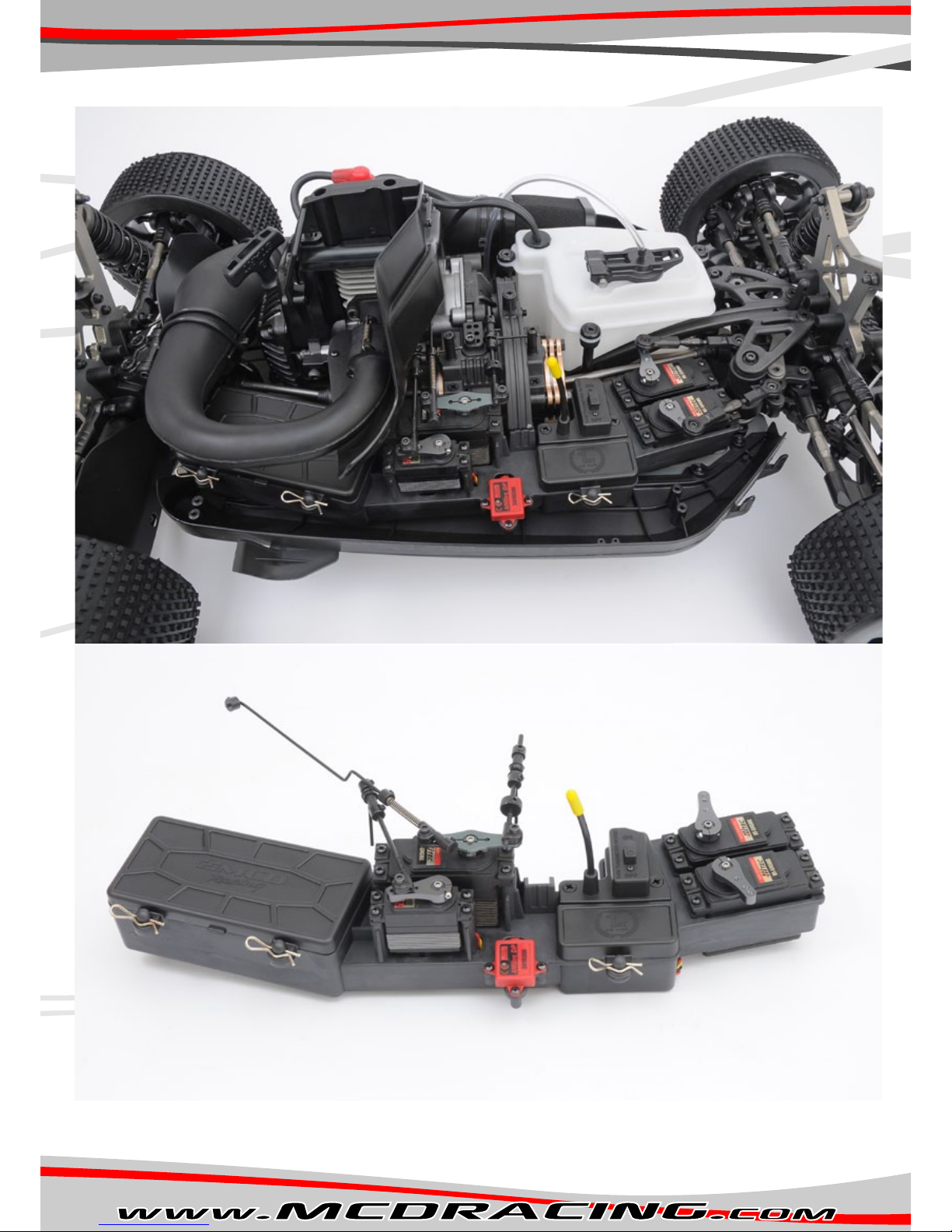
475101P Radio/Servo Tray 30x60mm Futaba/Hitec Std.4751 1
475102P Radio/Servo Tray 30x66mm Savox (Opt.)4751 1
475201P Radio Tray Covers Set4752 1
475301P Standard Size Servo to 30x60 Adapter4753 3
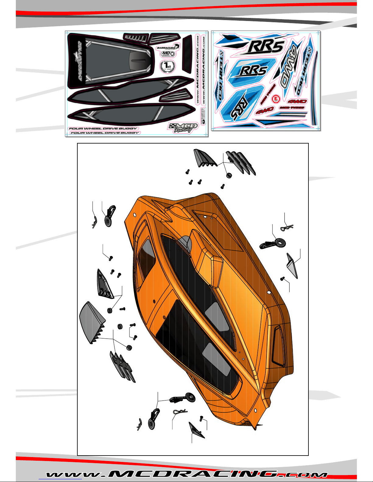
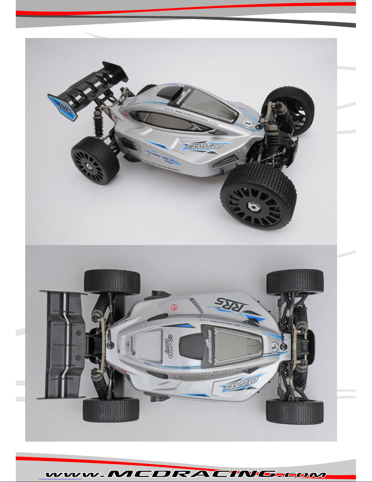
500101P RR5 Body Shell Kit Complete5001 1
500201P RR5 Body Shell Composite Accessories5002 1
500202P RR5 Body Shell Decal Set5002 1
500301P Buggy Rear Wing5003 1
500401P Buggy Rear Wing Mounts5004 1
500601P Rear Wishbone Mudguards5006 1
500701P Body Mount Clip Holder5007 4
500801S Body/Tray Clips5008 10
600101S Ball Bearing 687 2RS (7x14x5)6001 4
600201S Ball Bearing 689 2RS (9x17x5)6002 4
600301S Ball Bearing 6900 2RS 10x22x66003 2
600401S Ball Bearing 6901 2RS 12x24x66004 2
600501S Ball Bearing 6903 ZZ 17x30x76005 2
600601S Ball Bearing 6804 2RS 20x32x76006 2
600701S Ball Bearing 6000 2RS 10x26x86007 2
605101S Roller Pin 4x20 mm6051 10
605201S Roller Pin 4x35 mm6052 5
605301S Roller Pin 5x24 mm6053 5
605401S Roller Pin 5x40 mm6054 2
610101S Fuel Tank Cap Ball Set6101 1
610201S Drive Ball 6 mm6102 25
615101S LSD Diff. Shim 10x16x0.36151 10
615201S Pinion Gear Shim 16x22x16152 5
620101S CS PZ2 Self Tap 4x25 mm6201 10
620201S CS PZ2 Self Tap 4x70 mm6202 10
620301S CS PZ2 Self Tap 5x30 mm6203 10
625101S BH PH1 Self Tap 3x9 mm6251 25
625201S BH PH1 Self Tap 3x13 mm6252 10
630101S CH Hex Screw M4x8 mm6301 10
630201S CH Hex Screw M4x12 mm6302 10
630301S CH Hex Screw M4x16 mm6303 10
630401S CH Hex Screw M4x25 mm6304 10
630501S CH Hex Screw M4x30 mm6305 10
630601S CH Hex Screw M4x35 mm6306 10
630701S CH Hex Screw M5x10 mm6307 10
630801S CH Hex Screw M5x16 mm6308 10
630901S CH Hex Screw M5x40 mm6309 10
631001S CH Hex Screw M6x20 mm6310 10
631101S CH Hex Screw M5x25 mm6311 10
631201S CH Hex Screw M3x6 mm6312 10
631301S CH Hex Screw M3x12 mm6313 10
631401S CH Hex Screw M3x20 mm6314 10
635101S CS Hex Screw M4x12 mm6351 10
635201S CS Hex Screw M5x16 mm6352 10
640101S BH Hex Screw M4x25 mm6401 10
640201S BH Hex Screw M6x30 mm6402 10
645201S Set Screw M4x4 mm6452 10
645301S Set Screw M5x6 mm6453 10
645401S Set Screw M5x12 mm6454 10
645501S Set Screw M6x6 mm6455 10
645601S Set Screw M6x20 mm6456 10
650101S Self Lock Nut M36501 20
650201S Self Lock Nut M46502 20
650301S Self Lock Nut M56503 20
650401S Self Lock Nut M66504 10
655101S Plain Washer 4 mm6551 20
655201S Plain Washer 5 mm6552 20
655301S Plain Washer 6 mm6553 10
665101S Snap Ring 1x10 mm6651 10
670101R LSD Diff. O-Ring 1.5x10 mm6701 20

19
Product Code Product NamePart No Package Count
07 Air,Fuel and Exaust
670201R Fuel Tank Cap Viton O-Ring 3x22 mm6702 2
670301R Floating Shock Piston O-Ring 1.5x18 mm6703 10
670401R Shock Preload Wheel O-Ring 1.5x26 mm6704 10
675101P Brake Linkage Silicone Hose 5 cm6751 1
670501R Tune Pipe Holder O-Ring 4x60 mm6705 5
675201P Fuel Line Hose PU6752 1
700101P Fuel Tank Body7001 1
700201P Fuel Tank Lid / Posts Composite Set7002 1
700301R Fuel Tank I/O Rubber7003 2
700401R Fuel Tank Post Rubber7004 3
700501S Fuel Tank Lid Pin / Spring / Clip7005 1
725101P Air Filter Body Composite7251 1
725201P Air Filter Holder7252 1
725301P Carburetor / AirFilter Venturi7253 1
725401R Air Filter/ Carburetor L Tube TPE Rubber7254 1
725501P Air Filter Foam Standard For Dry7255 1
725502P Air Filter Foam For Rain7255 1
725601P Air Filter Easy Clamp7256 1
750101P Exhaust Holders High Temp Composite7501 1
750201S Exhaust Manifold7502 1
750401R Exhaust Sealing Rubber7504 2
750501S Exhaust / Manifold Spring7505 6
750601X Barracuda G Performance Exaust Set7506 1
775101P Air Flow Set7751 1
Other manuals for RR5 Competition
1
Table of contents
Other MCD Racing Motorized Toy Car manuals