I
I
I
TABLE
OF
CONTENTS
I
SECTION
1
—
INTRODUCTION
1.1
I
I
1.3
I
1.4
I
1.5
I
I
SECTION
2
-
OPERATING
PROCEDURES
I
I
SECTION
3
—
INSTALLATION
I
SECTION
4
-
ALIGNMENT
CHECK
I
I
I
I
Hi
4.1
4.2
2.2.3
2.2.4
1.2.1
1.2.2
1.2.3
1.2.4
2-1
2-6
2-6
2-8
2-9
2-10
4-1
4-1
4-1
4-1
3-1
3-1
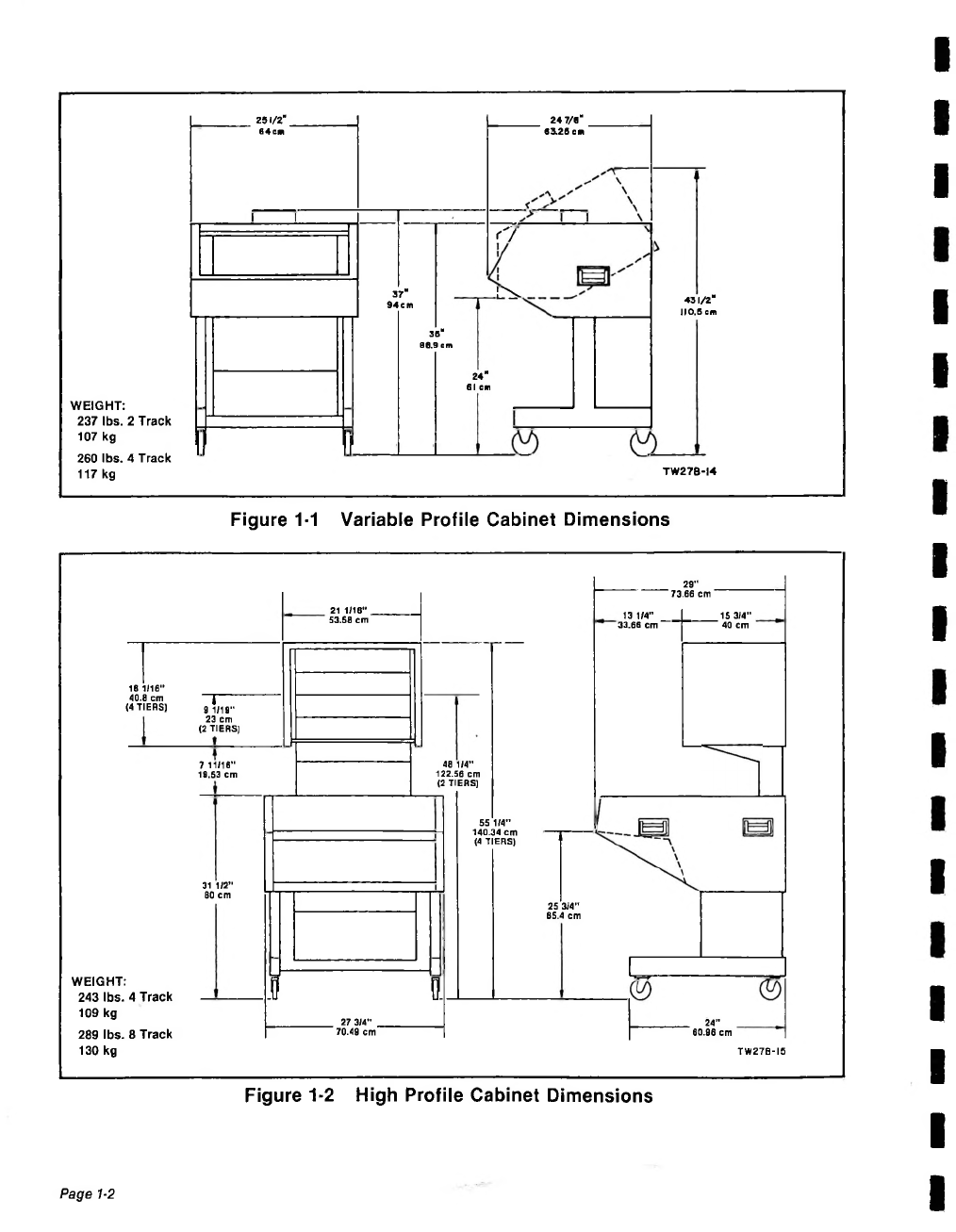
1-1
1-3
1-4
1-4
1-7
1-10
1-13
1-13
1-14
1-15
1-16
1-16
1-16
1-17
1-17
1-19
Intro uction
.......................
Equipment
Nee e
............
4.3
Transport
Alignment
Check
4.4
Au io
Alignment
Check
...
3.1
Unpacking
...........................
3.2
Groun ing
Consi erations
2.1
Controlsan
In icators
.....................
2.2
Operating
Proce ures
.......................
2.2.1
Transport
Motion
Controls.
..
2.2.2
Reference
an
Spee
Controls
RTZ
III
Autolocator
Controls
.
Au io
Controls
.........................
General
Information
............
1.2
Transports
.............................
JH-110B
.....................
JH-110B-14
.................
JH-110BC
..................
JH-110M
.....................
Au io
Electronics
.................
1.3.1
Stan ar
Electronics.
1.3.2
Broa cast
Electronics
1.3.3
Mastering
Electronics
RTZ
III
Autolocator
............
1.4.1
RTZ
III
........................
1.4.2
RTZ
HIM
....................
Power
Supply
.......................
1.6
Options
.................................
1.7
Accessories
.........................