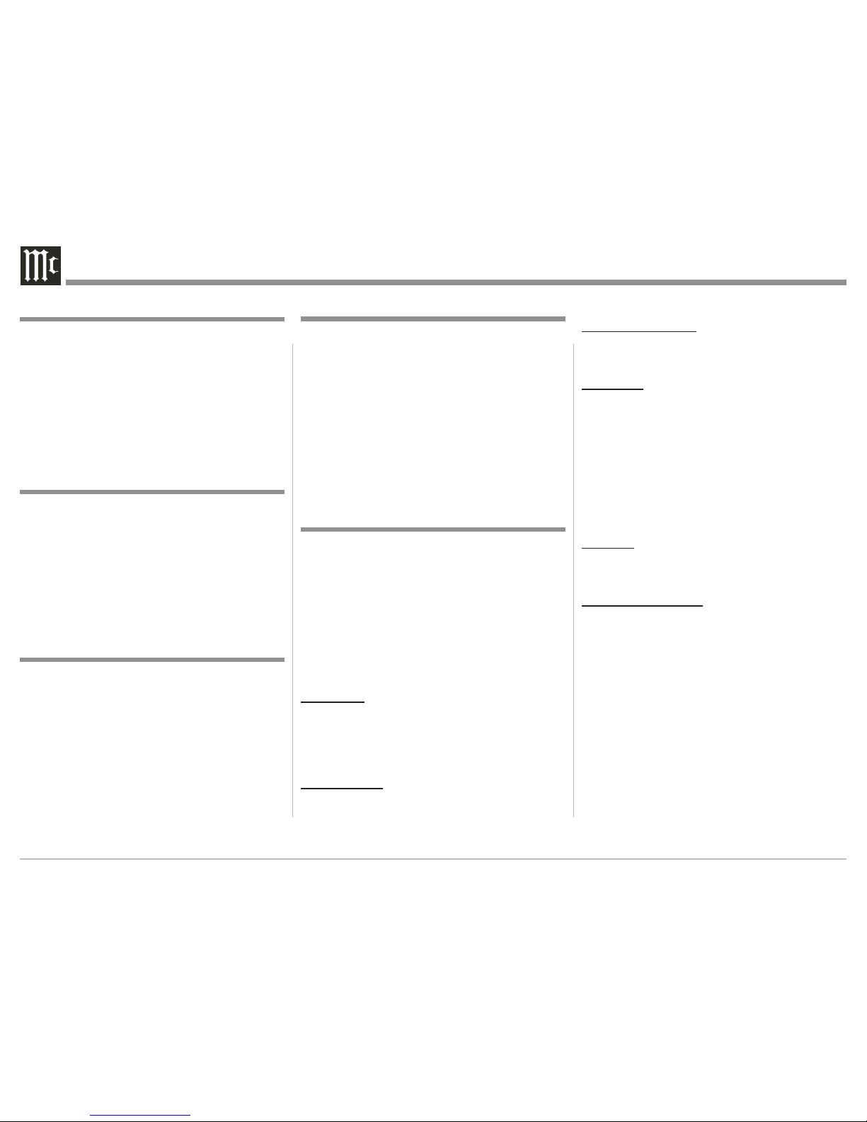
5
5. For additional information on the MXA60 and
other McIntosh Products please visit the McIntosh
Web Site at www.mcintoshlabs.com.
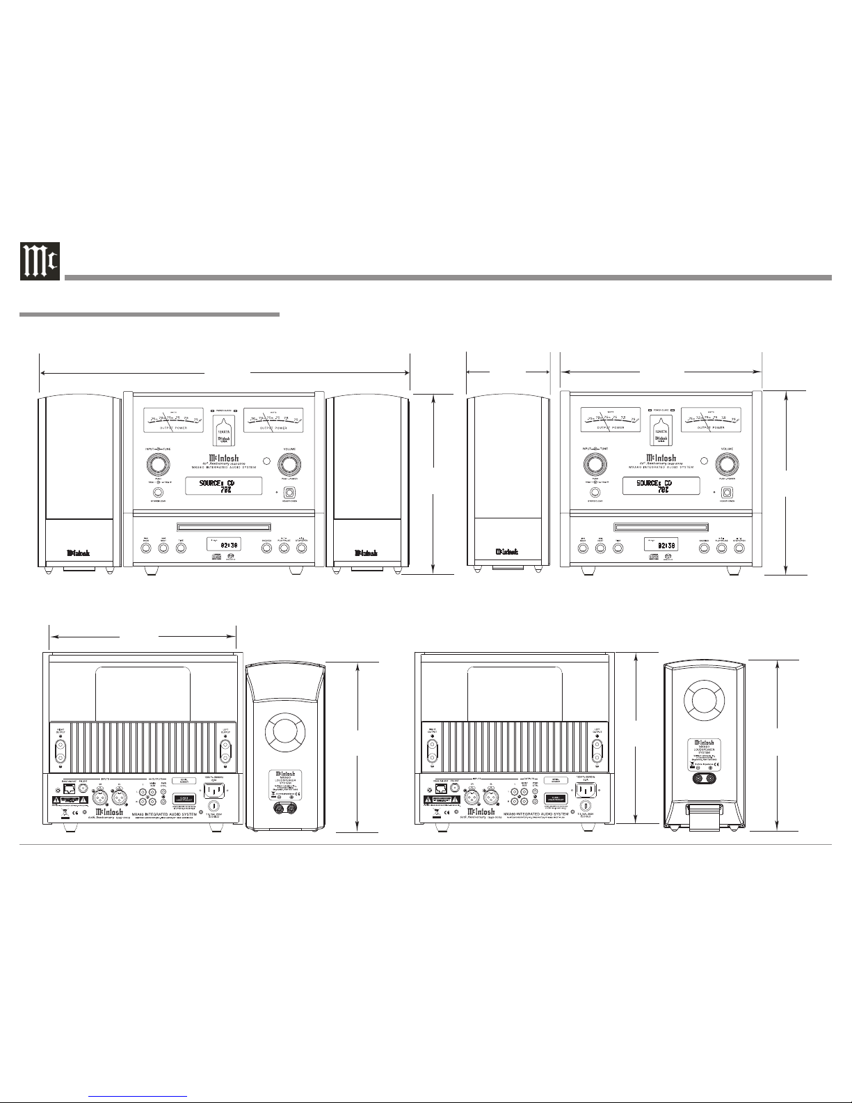
1. For additional connection information, refer to the
owner’s manual(s) for any component(s) connected
to the MXA60 Integrated Audio System.
2. The Main AC Power going to the MXA60 and any
other McIntosh Component(s) should not be applied
until all the system components are connected
together. Failure to do so could result in mal-
functioning of some or all of the system’s normal
operations. When the MXA60 and other McIntosh
Components are in their Standby Power Off Mode,
the Microprocessor’s Circuitry inside each com-
ponent is active and communication is occurring
between them.
3. In the event the MXA60 Power Amplifier over-
heats, due to improper ventilation and/or high
ambient temperature, the protection circuits will
activate. The Front Panel Power Guard LEDs will
continuously indicate ON and the audio will be
muted. When the MXA60 has returned to a safe
operating temperature, normal operation will
resume.
4. The MXA60’s built-in speaker protection incor-
porates an automatic resetting solid-state device
in the crossover network. The protection allows a
certain amount of overdrive, but extended periods
will trigger protection. If there is an obvious reduc-
tion of sound level the Protection Device may have
activated. The device will automatically reset when
the volume level setting on the MXA60 is reduced
significantly and kept low until the output of the
affected Loudspeaker returns to normal.
5. When discarding the unit, comply with
local rules or regulations. Batteries should
never be thrown away or incinerated but
disposed of in accordance with the local
regulations concerning battery disposal.
General Information
1. Compact Discs that are not round (e.g. Novelty
discs with octagonal or heart shapes) will not play
properly in the MXA60 and should not be tried, as
possible damage may occur.
2. The MXA60 SACD/CD Player is designed to play
all standard CD Audio Discs that conform to the
Official Compact Disc Standards which is indicat-
ed by the Symbol. It will also play most CD-R
and CD-RW discs, however some recorded discs
may not be able to play due to the condition of the
recording.
3. CD Audio Discs recorded in the MP3 and WMA
Formats will play on the MXA60, except discs that
contain multi-session recordings. Some MP3 or
WMA recorded discs may not be able to play due
to the condition of the recording. When ever pos-
sible, set the writing software to the ISO9660 Level
1 standard.
4. The CD audio side of the Dual Disc does not meet
the Compact Disc Digital Audio specifications
found in the industry “Redbook”; the MXA60 may
not read Dual Discs.
5. Several of the SACD performance features avail-
able on the MXA60 are active only if the SACD
Disc includes the supporting encoded information.
Disc Information
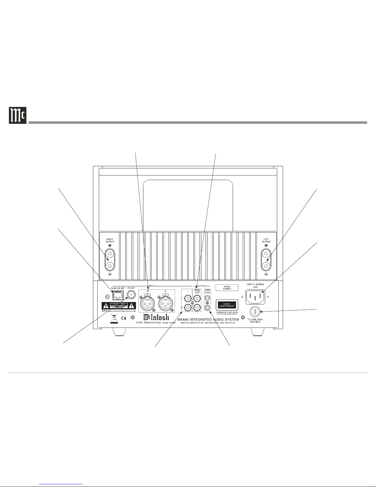
XLR Connectors
Below is the Pin configuration for the XLR Balanced
Input Connectors on the MXA60. Refer
to the diagram for connection:
PIN 1: Shield/Ground
PIN 2: + Output
PIN 3: - Output
Power Control Connector
The MXA60 Power Control Output Jack sends Power
On/Off Signal (12V) when con-
nected to other McIntosh Com-
ponents. A 1/8 inch stereo mini
phone plug is used for connection
to the Power Control Output on the
MXA60.
Note: The Power Control Connecting Cable is available
from the McIntosh Parts Department:
Power Control Cable Part No. 170-202
Six foot, shielded 2 conductor, with 1/8 inch stereo
mini phone plugs on each end.
RAA2 Connectors
Pin No. Wire Color
1. White/Orange
2. Orange
3. White/Green
4. Blue
5. White/Blue
6. Green
7. W hite/ Brown
8. Brown
*Cable outer shield
Note: The RAA2 Connecting Cable is available from the
McIntosh Parts Department:
RAA2 Antenna Cable Part No. 171844
Twenty foot, shielded 8 conductor, with a shielded
RJ45 connector on each end.
Connector and Cable Information