McLelland CA1250 User manual

Right Left
Right Left
Right Left
Right Left
Right Left
Right Left
CA1250
12 CHANNEL
6 ZONE
INTEGRATED AMPLIFIER
CA1250

2
• Explanation of Graphical Symbols
The lightning flash with arrowhead symbol, within an equilateral triangle, is
intended to alert you to the presence of uninsulated “dangerous voltage” within
the product’s enclosure that may be of sufficient magnitude to constitute a risk
of electric shock to persons.
The exclamation point within an equilateral triangle is intended to alert you to
the presence of important operating and maintenance (servicing) instructions in
the literature accompanying the product.
CAUTION: TO PREVENT ELECTRIC
SHOCK, MATCH WIDE BLADE PLUG TO
WIDE SLOT, INSERT FULLY.
ATTENTION: POUR EVITER LES
CHOCS ELECTRIQUES, INTRODUIRE
LA LAME LA PLUS LARGE DE LA FICHE
DANS LA BORNE CORRESPONDANTE
DE LA PRISE ET POUSSER JUSQU AU
FOND.
RISK OF ELECTRIC SHOCK
DO NOT OPEN
RISQUE DE CHOC ÉLECTRIQUE
N'OUVREZ PAS
CAUTION: To reduce the risk of electric shock, do not remove cover (or
back).
No user-serviceable parts inside. Refer servicing to qualified service
personnel.
1. Read these instructions.
2. Keep these instructions.
3. Heed all warnings.
4. Follow all instructions.
5. Do not use this apparatus near water.
6. Clean only with a dry cloth.
7. Do not block any ventilation openings. Install in accordance with the manufacturer’s instructions.
8. Do not install near any heat sources such as radiators, heat registers, stoves, or other apparatus (including amplifiers) that produce heat.
9. Do not defeat the safety purpose of the polarized or grounding-type plug. A polarized plug has two blades with one wider than the other. A grounding-type
plug has two blades and a third grounding prong. The wide blade or the third prong are provided for your safety. If the provided plug does not fit into your
outlet, consult an electrician for replacement of the obsolete outlet.
10. Protect the power cord from being walked on or pinched particularly at plugs, convenience receptacles, and the point where they exit from the apparatus.
11. Only use attachments/accessories specified by the manufacturer.
12. Use only with the cart, stand, tripod, bracket, or table specified by the manufacturer, or sold with the apparatus. When a cart is used, use caution when
moving the cart/apparatus combination to avoid injury from tip-over.
13. Unplug this apparatus during lightning storms or when unused for long periods of time.
14. Refer all servicing to qualified service personnel. Servicing is required when the apparatus has been damaged in any way, such as power-supply cord or plug
is damaged, liquid has been spilled or objects have fallen into the apparatus, the apparatus has been exposed to rain or moisture, does not operate normally,
or has been dropped.
15. The apparatus shall not be exposed to dripping or splashing and that no objects filled with liquids, such as vases, shall be placed on the apparatus.
16. CAUTION: Servicing instructions are for use by qualified service personnel only. To reduce the risk of electric shock, do not perform any servicing other than
that contained in the operating instructions unless you are qualified to do so.
17. WARNING: To reduce the risk of fire or electric shock, do not expose this apparatus to rain or moisture.
PORTABLE CART WARNING
Important Safety Instructions

3
Table of Contents
Important Safety Instructions............................................................................................................ 2
Table of Contents ............................................................................................................................... 3
Introduction......................................................................................................................................... 4
Features............................................................................................................................................... 5
What’s Included .................................................................................................................................. 5
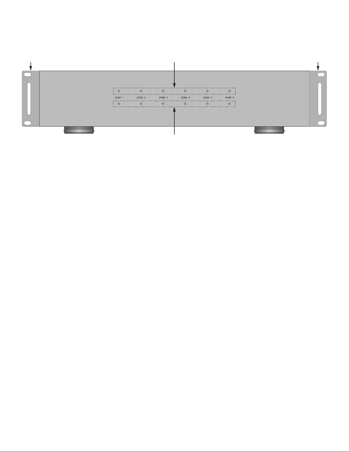
Front Panel Features.......................................................................................................................... 6
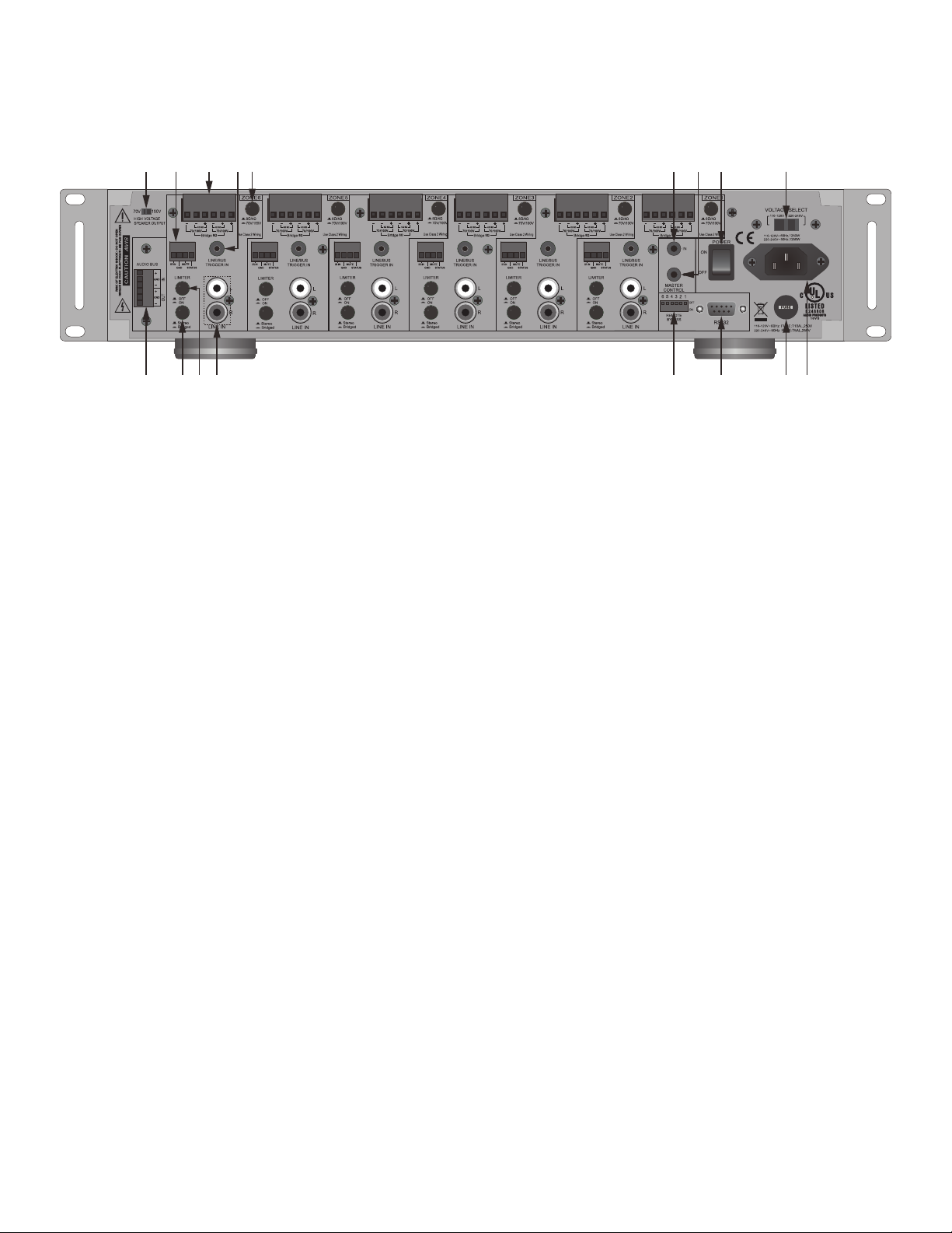
Rear Panel Features........................................................................................................................... 7
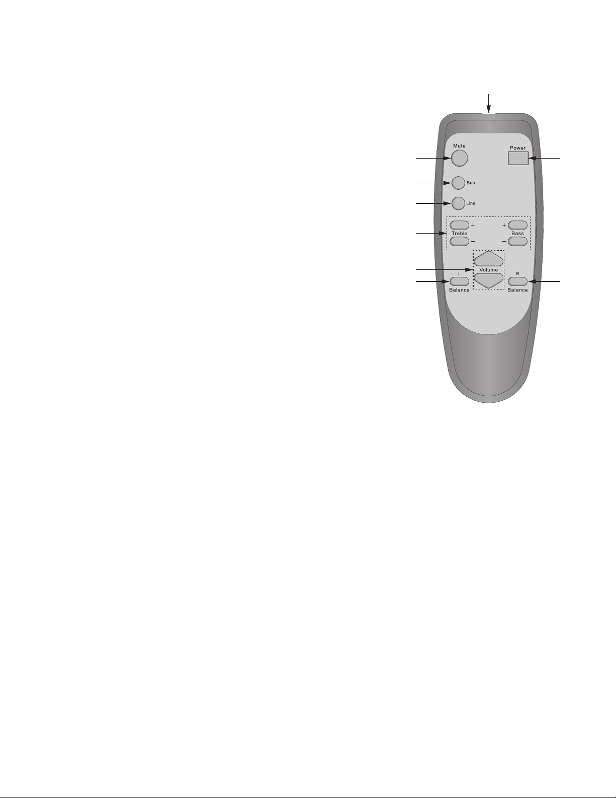
IR Remote Control.............................................................................................................................. 9
Installation......................................................................................................................................... 10
Wiring Infrastructure........................................................................................................................ 11
Speaker Wire ............................................................................................................................... 11
Multi-zone Audio (4/8 Ohms) ....................................................................................................11
Multi-room Audio - Stereo or Bridged (4/8 Ohms) ....................................................................11
70V/100V..................................................................................................................................11
Connections...................................................................................................................................... 12
Speaker Connections ................................................................................................................. 12
............................................................................................................................... 12
..................................................................................................................................... 12
70V/100V................................................................................................................................. 13
Audio Connections ..................................................................................................................... 14
Zone Line IN ............................................................................................................................ 14
Audio Bus IN ........................................................................................................................... 14
Audio Bus OUT ....................................................................................................................... 14
Control Connections................................................................................................................... 15
Zone IR IN .............................................................................................................................. 15
Zone Mute ............................................................................................................................... 16
Zone Status OUT .................................................................................................................... 16
Zone Line/Bus Trigger IN ........................................................................................................ 16
Master Control IN..................................................................................................................... 17
Master Control OUT................................................................................................................. 17
RS232 I/O................................................................................................................................ 17
Settings ............................................................................................................................................. 18
70/V100V High Voltage Speaker Output ................................................................................. 18
................................................................................................ 18
Stereo/Bridged Zone Setting ................................................................................................... 18
Limiter...................................................................................................................................... 18
Remote Bypass ....................................................................................................................... 19
Voltage Select/Fuse................................................................................................................. 19
Operation........................................................................................................................................... 21
Voltage Controlled ................................................................................................................... 21
IR Controlled............................................................................................................................ 21
RS232 Controlled .................................................................................................................... 22
RS232 Commands............................................................................................................................ 23
RS232 Queries .................................................................................................................................. 25
RS232 Settings ................................................................................................................................. 27
................................................................................................................................... 29
Limited Warranty .............................................................................................................................. 30

4
Introduction
Congratulations and thank you for purchasing the McLelland CA1250 12 Channel
The CA1250 is, at its core, a twelve channel audio distribution amp....but it can also do so many
other things.
C
4 Ohm/8 Ohm zones (30W/channel @ 8 Ohms; 50W/channel @ 4 Ohms); but it can also be
configured for six stereo 70/100V zones (30W/channel); or three high powered bridged zones(100W
@ 8 Ohms). By the way, the CA1250 can be configured for any combination of stereo 4 Ohms/ 8
Ohms, 8 Ohms bridged and 70/100V zones all at the same time!
And there’s more. Each zone can be controlled via IR or RS232 for ON/OFF, Input, Volume/Mute,
Treble/Bass and Left/Right Balance. The RS232 section is bi-directional with an easy to configure
command structure. The CA1250 can be configured to automatically send zone status updates or
respond to queries to confirm zone status and settings. Commands for volume, treble/bass and
balance can be specific values or step commands depending upon the control application.
The CA1250 has an Audio Bus IN that can be manually selected by IR commands, RS232
commands or voltage trigger. The voltage trigger will switch a zone to the Audio Bus IN as long
as there is voltage present on the zone Line/Bus Trigger IN. When the voltage is cut, the zone
automatically switches back to the zone Line IN. Great for momentary switching to an audio page on
the Bus IN!
Each zone has a Mute Trigger IN that will mute zone audio when voltage is present on the Mute
Trigger IN. When the voltage is cut, the zone audio output resumes.
Each zone has a 12VDC Status or Control OUT that can be used to activate a zone specific volatge
controlled device or otherwise indicate zone ON/OFF status.
Each zone has a -20dB audio limiter to prevent incidental peaks from becoming consequential
damage.
The CA1250 features a Remote Bypass switch that allows/blocks IR and RS232 commands from
select zones for zones that are intended to be user controlled or set and not messed with.
Finally, the CA1250 has a 110~120V/220~240V select switch allowing it to be used just about
anywhere there is AC Voltage.
The CA1250 is also rack mountable and comes with removable rack ears.
The McLelland CA1250 12 channel x 50W audio distribution amp...ready for anything... anywhere.
Please read and follow the instructions in this guide to assure proper installation and maximum
performance of your new McLelland CA1250.

5
Features
•
Bus input (unbalanced)
•
• All zones are independently controllable via RS232, IR and voltage trigger lines
• Each zone has -20dB Audio Limiter
• Each zone has an independent mute trigger input (activated by +3 to +30V DC)
• Each zone has an individual Trigger Output (+12V DC) that coresponds to zone ON/OFF status
• Front panel features “Zone ON” and “Zone Overload” LED indicators for each zone
• Master global Control In (+3 to +30V DC) and Control Out (+12V DC)
• Detachable screw-terminal connectors for global Audio Bus IN/OUT, Zone IR IN, Zone Mute, Zone
Status OUT and Zone Speaker Outputs
• Rack mountable in standard 19" rack (2U height)
• Selectable 110/220 AC volatge
What’s Included
CA1
1 - IR Remote Control
1 - AC Power Cord
1 - User Manual
CAUTION!!!
NEVER CHANGE ANY OF THE FOLLOWING SETTINGS WHEN THE CA1250 IS TURNED
ON OR CONNECTED TO AC POWER:
70V/100V HIGH VOLTAGE SPEAKER OUTPUT
ZONE STEREO/BRIDGED SWITCH
VOLTAGE SELECT SWITCH (110/220VAC)
DOING SO CAN CAUSE SEVERE DAMAGE TO THE CA1250 AND/OR CONNECTED
SPEAKERS. THIS TYPE OF DAMAGE IS NOT COVERED UNDER WARRANTY.

6
21 1
3
1. RACK EARS - Two, optional rack ears. The CA1250 is 2U rack height. If rack mounting, leave
desired.
2. PEAK OUTPUT LEDS -
volume setting. This is an indication that the volume setting is approaching maximum...not an
a bit to protect the amp and speakers.
3. ZONE POWER LEDs - Six, green LEDs illuminate solid green when a stereo zone is ON. LED
turns WHITE when Zone is OFF.
Front Panel Features

7
Right Left
Right Left
Right Left
Right Left
Right Left
Right Left
12 3 4 5 6 7 8 9
1011121314151617
1. SYSTEM 70/100 VOLT SELECT - One, switch. Slide switch to select between 70V and 100V for a high-
voltage audio distribution system. This setting will affect all zones in 70V/100V mode. Set for 70V when
voltage select is set to 110-120VAC; Set for 100V when voltage select is set to 220-240VAC.
2. ZONE IR, MUTE & STATUS TERMINAL - Six, plug-in screw terminals. Provides connections for zone
IR IN - Connect IR IN & GND to the Emitter OUT on an IR Control system for zone IR control using the
CA1250 IR Remote.
Mute - Connect to a +3 to +30VDC @1mA control voltage to mute the local zone.
Status - Provides a 12VDC 1mA Control OUT to trigger zone specific voltage controlled devices.
3. ZONE SPEAKER TERMINAL- Six, plug-in screw terminals. Each terminal has six connections for different
Use indicated terminals for high output mono speaker connection. (100W @ 8 Ohms)
Use indicated terminals for normal stereo speaker connections. (30W @ 8 Ohms;
50W @ 4 Ohms)
70V/100V - Use indicated terminals for 70V/100V stereo speaker connections. (30W @ 70V/100V)
4. ZONE LINE/BUS TRIGGER IN- Six, 3.5mm mini jacks. This voltage controlled input switches the zone
audio input from Line IN to Audio Bus IN. When there is no voltage applied, the zone audio input is zone
Line IN. When voltage is applied (+3 to +30VDC @1mA) the zone audio input will switch to Audio Bus IN.
Six, push buttons. Press to select 8 Ohms/4 Ohms - 70V/100V by
zone. Leave OUT to select 8 Ohms/4 Ohms, press IN to select 70V/100V.
6. MASTER CONTROL IN - One, 3.5mm mini jack. Connect to a +3 to +30VDC @1mA control voltage to turn
7. MASTER CONTROL OUT - One, 3.5mm mini jack. Connect to any voltage controlled device that is to be
turned ON/OFF relative to CA1250 ON/OFF Status. When any zone on the CA1250 is ON the Master
Control OUT will output 11.5VDC@1mA-10VDC@5mA. When all zones are OFF the Master Control OUT
Rear Panel Features

8
is 0.0VDC.
8. POWER ON/OFF SWITCH - One, switch. Set to ON position to turn power to the amp ON. Set to OFF
position to turn power to the amp OFF.
9. VOLTAGE SELECT SWITCH - One, switch. Select either 110V-120V or 220V-240V as appropriate for local
10. AC MAINS - One, three-prong socket. Use the supplied 3-pin ground power cable to connect the unit to an
external AC power supply.
11. FUSE - One, replaceable fuse. For 110V-120V/60Hz use a T10.0AL/250V fuse. For 220V-240V/50Hz use a
T5.0AL/250V fuse.
12. RS232 TERMINAL - One, DB9F terminal. Connect to an automation system or other controller for two-way
communication with and control of the CA1250.
13. REMOTE BYPASS - One, six position DIP switch. Set to OFF to allow IR/RS232 control of the selected
zone. Set to ON to block IR/RS232 control of the selected zone.
14. ZONE LINE IN - Twelve, RCA jacks. Connect to the L & R line level OUTs on an audio source that is to be
15. ZONE AUDIO LIMITER - Six, push buttons. Press to activates a -20dB input limiter, for both channels, to
help reduce the level of accidental audio peaks and clipping distortion by zone. Leave in the OUT position
to pass audio through unprocessed, press IN to activate the input limiter.
16. STEREO/BRIDGED - This switch
information.
Stereo - For stereo signals, leave switch in the OUT (Stereo) position. This applies to all connections in
the 8 Ohm/4 Ohm and 70V/100V configurations.
Bridged -
designed to run safely into such a low impedance (which the CA1250 is not) damage may
17. AUDIO BUS - One, plug-in screw terminal. Mono, unbalanced input. This input will send the Audio IN
signal to all zones switched to Bus using the Line/Bus Trigger IN. It can also send the Bus Audio IN signal
to another CA1250 via the Audio Bus OUT.
Rear Panel Features

9
IR Remote Control
The CA1250 IR Remote Control controls the individual zones on the
CA1250. It can also be used to teach IR commands to a
programmable, integrated IR remote, zone control system or other
IR routing device.
controller or IR router will be necessary for centralized control of the
individual zones. Local zone control can be easily accommodated
with a local IR receiver and an IR Remote.
1
2
3
4
5
6
7
8
7
1. IR LED -
(infrared) light pulses that are the control codes for the CA1250.
The LED must be pointed at an IR receiver that is connected to
an CA1250 Zone IR IN.
2. MUTE - With audio playing in a zone, press this button to mute
the zone audio output. Press again to un-mute.
3. BUS - Press this button to select the audio source playing
through the Audio Bus IN.
4. LINE - Press this button to select the audio source playing
through the local zone Line IN.
5. TREBLE/BASS - Press the Treble +/- buttons to increase/decrease the accent of high frequencies
in the zone audio output. Press the Bass +/- buttons to increase/decrease the accent of low
frequencies in the zone audio output. Season to taste.
C
6. VOLUME - Press the Volume + button to increase zone audio output. Press the Volume - button to
decrease zone audio output.
7. BALANCE L/R - Press the Balance L button to increase volume in the left speaker relative to the
right speaker. Press the Balance R button to increase volume in the right speaker relative to the
C for
additional information.
8. POWER - Press this button to turn the local zone ON. Press again to turn the local zone OFF.

10
Installation
1U Rack Vent Above CA1250
1U Rack Vent Below CA1250
C
adequate cooling.
C
surfaces.
above the top cover. Be sure there are large openings in the shelf below the unit and in the
cabinet to allow the entry of cool air and the escape of warm air.
4. If the cabinet contains other heat generating components or several CA1250’s are being used,
be sure to provide adequate ventilation to dissipate heat the units can generate.
C
and the other heat generating components.
6. When installing the CA1250 in a rack, please use racks that feature a rear support provision.
Adding a single RU (Rack Unit) vent above and below the CA1250 will improve convection in
heavy use applications. [One Rack Unit size = 1-3/4" (44.5mm) in height]. Also try to mount the
7. Be sure to leave adequate space for large bundles of wire and dress them in such a manner that
require service.

11
Wiring Infrastructure
Speaker Wire
C
system can create different requirements for speaker wire runs. Please review the information below
and apply these guidelines to your particular application(s).
If the CA1250 is being used with a multi-zone preamp/controller then pull home-runs directly from the
speaker locations or speaker terminal plates to the amplifier location. Use quality stranded
If the amp is being used to distribute audio from the CA1250 Zone Line INs or Audio Bus IN, to
different rooms with 4/8 Ohm speakers, individual room volume controls (or an IR control system) will
be needed. In this application pull speaker wire from each speaker to the volume control location in
each room and then home-runs from each volume control to the amplifier location. Use quality
SPEAKER WIRE LENGTH SPEAKER WIRE GAUGE
150’ (46m) 16 AWG
400’ (122m) 14 AWG
1000’ (305m) 12 AWG
70V/100V
If the amp is being used to distribute 70V/100V audio, pull distribution lines (each distribution line is
a wire pair) in a daisy-chain pattern, (amp to first speaker, first speaker to second speaker, second
speaker to third speaker, etc.) If distributing stereo, pull two distribution lines (two pair) to each
speaker location in a daisy chain from the amp location. Use quality stranded speaker wire based
upon the 70V Speaker Wire Gauge Table below.
70V SPEAKER WIRE GAUGE (30W Zone Output)
SPEAKER WIRE LENGTH SPEAKER WIRE GAUGE
350’ (106m) 24 AWG
550’ (167m) 22 AWG
900’ (274m) 20 AWG
1400’ (426m) 18AWG
2300’ (701m) 16AWG

12
Connections
Speaker Connections
C
speaker connections. Bridged 8 Ohms, 4/8 Ohms
Stereo and 70V/100V. Any mix of amplifier modes
is allowable in different zones...as long as they
are configured correctly. NEVER CHANGE THE
70V/100V HIGH VOLTAGE SPEAKER OUTPUT,
8
SETTINGS WHILE THE AMP IS TURNED ON OR
CONNECTED TO AC POWER!!!
Bridging a zone amp creates an 8 Ohm,110 Watt
zones for stereo.
1. Stereo/Bridged Switch - Set to the Bridged
position.
position.
3. Speaker Connections - Connect the wire from
Bridged
4. Zone Line IN - Connect the source left channel
OUT to the left channel Line IN on the LOWER
NUMBERED bridged zone. Connect the source
right channel OUT to the left channel Line IN on
the HIGHER NUMBERED bridged zone.
speaker output. (30W @ 8 Ohms/50W @ 4 Ohms)
1. Stereo/Bridged Switch - Set to the Stereo
position.
position.
3. Speaker Connections - Connect the wire from
Repeat for the left
channel speaker.
4. Zone Line IN - Connect the L & R line level OUT
on the zone audio source to the appropriate
zone L & R LINE IN.
High Power
8Speaker
Right LeftRight Left
High Power
8Speaker
8
Set to: 8
Bridged
Set to: Bridged
Bridge 8
Right Left
Medium Power
4/8Speaker
8
70V/100V Switch
Set to: 8
Stereo/Bridged
Switch
Set to: Stereo
4/8
-/+ Terminals
Right Left

13
Connections
70V/100V
zone. (30W/channel) A 70V/100 V system utilizes
speakers with special taps that set the wattage/
volume of each speaker.
70V/100V speaker system are wired using a
speaker, then that speaker connects to the next
speaker and so on.
When setting an CA1250 zone for 70V/100V, be
sure to accurately calculate the total wattage
required and not exceed the CA1250 70V/100V
zone’s output, 30W per channel in 70V/100V mode.
Typically 70V amp power requirement can be
calculated by adding the total of the tap wattage
set for all speakers to be connected to a 70V/100V
zone and multiplying it by 1.2. This will allow
of system.
If the total wattage exceeds 30 Watts for a 70/100V
zone, reduce the load to any given zone by
connecting 70V/100V speakers to multiple zones
set to 70V/100V to safely distribute the load.
Right Left
Low/Medium Power
70V/100 Speakers
8
70V/100V Switch
Set to: 70V/100V
Stereo/Bridged
Switch
Set to: Stereo
70V/100V
-/+ Terminals
Right Left
Right Left
70V Speaker
Parallel IN/OUT
70V Speaker
Parallel IN/OUT
IN
OUT
IN
OUT
70V/100V
Distribution Lines
Set 70V/100V
for all 70V/100V
Zones. See text.
4. Speaker Connections - Connect the right 70V distribution line +/- wires to the right 70V/100V
70V/100V Connection. If configuring stereo, Repeat for the left channel
speaker.
Connect the right channel +/- distribution lines to the IN terminals on the first 70/100V speaker. Repeat
for the left channel.
Connect the right/left channel +/- distribution lines to the OUT terminals on the first 70/100V speaker.
Connect the right/left channel +/- distribution lines to the IN terminals on the next 70/100V speaker.
Ohm system. But it is
critically important that the connections be consistent, that is, plus to plus, minus to minus.
5. Zone Line IN - Connect the L & R line level OUT on the zone audio source to the appropriate zone L &
R LINE IN.
1. 70V/100V High Voltage Speaker Output - Set 70V/100V Connection
to 70V if CA1250 AC Voltage Select switch
is set to 110~120VAC. Set to 100V if CA1250 AC Voltage Select switch is set to 220~240VAC. This
setting will affect all zones set to 70V/100V.
2. Stereo/Bridged Switch - Set to the Stereo position.
Set to the 70V/100V position.

14
Connections
Audio Connections
ZONE LINE IN
This connection is an input for a dedicated zone
line-level audio source. If multiple line level audio
sources are required in a zone, use an audio switch
on the zone Line IN or use a multi-source, multi-
zone controller if multiple audio sources are required
in multiple zones.
1. Line IN - Using a quality, stereo audio RCA-RCA
patch cable with gold ends, connect the L&R line
level OUTs on the audio source to the L&R Line
INs on the appropriate CA1250 zone.
AUDIO BUS IN
This connection will distribute unbalanced line level
Trigger IN.
If connecting a stereo line level device, use an
when making this connection.
1. IN - Connect the RCA to bare wire adapter to
the Audio Bus IN +/GND terminals as shown.
2. Connect the Audio Bus IN Source to the RCA
adapter. Use a stereo to mono adapter if
connecting a stereo source.
pin = signal, sleeve =GND.
AUDIO BUS OUT
This connection will send the unbalanced line level
audio source connected to the Audio Bus IN to the
Audio Bus IN on another CA1250 or other audio
amplifier.
1. OUT - Using either the RCA adapter or bare
wire, connect the Audio Bus OUT +/GND
terminals on CA1250 #1 to the Audio Bus IN+/
GND terminals on CA1250 #2. Use an RCA to
bare wire adapter if connecting to a device with
line level RCA jacks.
pin = signal, sleeve =GND.
Optional
RCA Stereo to Mono
Adapter
(Not Included)
Connect to Line Level
Stereo Audio Source
Connect to Line Level
Mono Audio Source
CA1250 #1
CA1250 #2
Jump CA1250 #1
Audio Bus OUT to
CA1250 #2 Audio
Bus IN
RCA to
Bare Wire
Adapter
(Included)
Audio Bus IN/OUT Connections
LINE OUT
L
R
Stereo Line Level
Audio Source
CA1250 Zone
Line IN
RCA Stereo
Patch Cable
Zone Line IN Connections

15
IR Receiver
IR Connecting Block
12VDC
Power Supply
IR Remote
CA1250 Zone IR Input
1. IR/GND - Using a 2-circuit 3.5mm mini plug cable, connect the IR Emitter OUT of an IR control
system to the IR IN and GND terminals on the appropriate CA1250 zone. Connect the white
stripe (tip) to IR IN, connect the black (sleeve) to GND.
ZONE MUTE
This connection allows voltage control of zone mute. Applied voltage (+3 to +30VDC @1mA) will
mute the zone speaker output. When the voltage is cut, zone speaker output is restored.
1. MUTE/GND - Using a 2-conductor stranded, non-shielded cable, connect +DC voltage and GND
from the trigger device to the MUTE and GND terminals on the appropriate CA1250 zone.
Connect +VDC to MUTE, connect GND to GND.
Connections
Control Connections
ZONE IR IN
This connection allows IR control of the connected zone for zone power, volume, mute, Line/Bus,
etc using the commands from the CA1250 IR Remote and a connected IR control system.
Zone IR Connections

16
1. Status/GND - Using a 2-conductor stranded,
non-shielded cable, connect STATUS (+DC
voltage) and GND from the CA1250 zone to the
Control IN (+VDC) and GND terminals on the
device to be controlled. If the controlled device
uses a jack, please refer to the product’s owner’s
ZONE LINE/BUS TRIGGER IN
This connection provides a voltage trigger to switch
the zone audio input from Line IN to Audio Bus IN.
When there is no voltage applied, the zone audio
input is zone Line IN. When voltage is applied the
zone audio input will switch to Audio Bus IN...an
excellent option for audio page override.
1. Line/Bus - Using a 2 circuit 3.5mm mini plug,
connect the voltage trigger to the appropriate
zone Line/Bus Trigger IN. Connect +12VDC
from the trigger device to the striped wire (tip).
Connect GND from the trigger device to the
unmarked wire (sleeve).
To +V/GND
on Trigger Device
To +V/GND
on Voltage Controlled Device
+12VDC
(Tip)
2 Circuit
Mini plug
GND
(Sleeve)
Stripe
Zone Mute Connection
Zone Voltage Control Connection
Zone Line/Bus Trigger Connection
Connections
ZONE STATUS OUT
This connection provides a +12VDC 1mA zone
control output that can be used to trigger zone
specific, voltage controlled devices. When an
CA1250 zone is ON, this connection will output a
+12VDC control voltage. When the zone is OFF the
control voltage is 0.OVDC

17
1. Master Control IN - Using a 2 circuit 3.5mm
mini plug, connect the voltage trigger to the
Master Control IN. Connect +3 to +30VDC
@1mA from the trigger device to the striped wire
(tip). Connect GND from the trigger device to the
unmarked wire (sleeve).
MASTER CONTROL OUT
This connection provides a voltage control OUT
that can be used for triggering voltage controlled
system devices that need to be turned ON when any
CA1250 zone is active. When any CA1250 zone is
ON, the Master Control OUT will output
+11.5VDC@1mA-10VDC@5mA. If all zones are
OFF, the Master Control OUT will output 0.0VDC.
1. Master Control OUT - Using a 2 circuit 3.5mm
mini plug, connect the CA1250 Master Control
OUT to the voltage controlled device(s). Connect
the striped wire (tip) to +12VDC on the controlled
device. Connect GND the unmarked wire
(sleeve) to GND on the controlled device.
RS232 I/O
This connection provides a two-way
communication terminal for control/status feedback
of the CA1250 from/to an automation system or
other appropriately capable device.
1. RS232 - Using a DB9 Patch Cable, connect the
CA1250 RS232 Terminal to an appropriate
RS232 terminal on an automation system
controller or other device. CA1250 RS232
DB9F pin-out is as shown. Please refer to the
RS232 terminal pin-out.
Connections
MASTER CONTROL IN
This connection allows voltage control of CA1250
ON/OFF. Applied voltage (+3 to +30VDC @1mA)
will turn the amp ON. When voltage is cut, the amp
will turn OFF. (OFF, not Standby.)
position when using this feature. With this feature
the IR and RS232 controls will not turn a zone ON
or have any other control unless proper voltage is
applied to the Control IN.
+12VDC
(Tip)
2 Circuit
Mini plug
GND
(Sleeve)
Stripe
+12VDC
(Tip)
2 Circuit
Mini plug
GND
(Sleeve)
Stripe
Pin 5
GND
Pin 3
Signal IN
Pin 2
Signal OUT
Master Control IN Connection
Master Control OUT Connection
RS232 Terminal Pin-Out

18
1. 70V/100V High Voltage Speaker Output -
Set to 70V if CA1250 AC Voltage Select
switch is set to 110~120VAC. Set to 100V if
CA1250 AC Voltage Select switch is set to
220~240VAC. This setting will affect all zones
set to 70V/100V.
Settings
This section covers all of the settings that need to
set correctly in order for the CA1250 to function
properly.
70/V100V HIGH VOLTAGE SPEAKER OUTPUT
for
70V/100V to either 70 volts or 100 volts.
This switch is used in conjunction with both the
70V/100V switch setting.
All zones set for 70V/100V will be affected by the
70/V100V High Voltage Speaker Output switch
setting, so be sure to have 70V/100V speakers
properly connected and configured when
changing this setting.
Right Left
70V/100V Speaker Output System Setting
Stereo/Bridged Zone Setting
Limiter Zone Setting
Speaker Connections for
STEREO/BRIDGED ZONE SETTING
Speaker Connections for full
LIMITER
This switch activates a -20dB audio limiter that will help reduce the level of accidental loud noises and
clipping distortion for both channels in a given zone.
1. Limiter - The Limiter is OFF with the switch in the OUT position. The Limiter is ON with the switch
in the IN position .

19
REMOTE BYPASS
The Remote Bypass switch allows/prevents IR
and RS232 control by zone. When the switch is
in the ON position (bypass zone) the zone will not
respond to IR or RS232 commands. When the
switch is in the OFF position, (do not bypass zone)
the zone will respond to IR and RS232 commands.
1. Remote Bypass - Set to ON position to block
IR and RS232 commands from controlling the
selected zone. Set to OFF position to allow IR
and RS232 control of the selected zone.
VOLTAGE SELECT/FUSE
This switch sets the voltage to the AC Mains.
Be sure to check AC voltage at the
geographic location where the CA1250 will be
installed.
1. Voltage Select - Set as appropriate for
geographic location. NEVER CHANGE THIS
SWITCH SETTING WHILE THE CA1250 IS
CONNECTED TO AC POWER!
2. Fuse-
installed for the selected AC Voltage. If set to
220V-240V/50Hz use a T5.0AL/250V fuse. If
set to 110V-120V/60Hz use a T10.0AL/250V
fuse.
Settings
Remote Bypass Switch
AV Voltage Select/Fuse
CAUTION!!!
NEVER CHANGE ANY OF THE FOLLOWING SETTINGS WHEN THE CA1250 IS TURNED
ON OR CONNECTED TO AC POWER:
70V/100V HIGH VOLTAGE SPEAKER OUTPUT
ZONE STEREO/BRIDGED SWITCH
VOLTAGE SELECT SWITCH (110/220VAC)
DOING SO CAN CAUSE SEVERE DAMAGE TO THE CA1250 AND/OR CONNECTED
SPEAKERS. THIS TYPE OF DAMAGE IS NOT COVERED UNDER WARRANTY.

L
R
IN OUT
1 2 3 4 5 6
ZONE 1
IR Receiver
Zone In Ceiling
Speakers
ZONE 2
Zone In Ceiling
Speakers
ZONE 3
Zone In Ceiling
Speakers
ZONE 4
Zone In Ceiling
Speakers
ZONE 5
Zone In Ceiling
Speakers
ZONE 6
Zone In Ceiling
Speakers
CA1250
Audio Distribution Amp A/V Receiver or
Other Audio Source Switcher
IR Connecting Block
CD/Blu-ray/Streaming Media Player
Tablet Smartphone/
Portable Music Player
Hardwired/Docked/
Bluetooth
Line Level Audio to
CA1250 Zone Line
INs
Line/Preamp
Out
Line Level Audio to
AVR/Switcher
Typical CA1250 System Application 20
Table of contents
Other McLelland Amplifier manuals

McLelland
McLelland Power Pro 300 User manual

McLelland
McLelland AVD-800P User manual

McLelland
McLelland MAP 1200HD User manual

McLelland
McLelland AVD-800P User manual

McLelland
McLelland McLelland D20BR User manual

McLelland
McLelland PLA2FX User manual

McLelland
McLelland MAP1200WD User manual

McLelland
McLelland PLA2 User manual

McLelland
McLelland MAP 1200 User manual

McLelland
McLelland BP-1 User manual