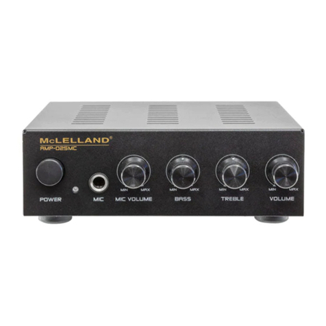
McLelland PR-150 User manual

STEREO POWER AMPLIFIER
OWNER MANUAL
PR-150
DESIGNED IN U.K.
PDF created with FinePrint pdfFactorytrial version http://www.fineprint.com

INTRODUCTION
Congratulations on your purchase of MA PR-150 StereoPower Amplifier.
The performance of PR-150 is perfect for anyaudio application, musician,
performer, studioengineer, andsoundcontractor. We have manyyears of
experience inmanufacturingaudio products, and excellent research and
development, have enableus toprovidean amplifier with the highest qualityand
reliability.
PR-150 was designedandmanufactured using only the best qualityof
components andmaterials. Eachamplifierdesign must satisfyour team of
highly-trained techniciansand musicians beforeit is approved.
FEATURES
300 WattsRMS.
Stereo/Mono Bridge Operation.
InternalProtection Circuitry.
ConvectionCooled.
Excellent Signal toNoise Ratio.
AutomaticRecoveryCircuit.
Aluminumfront panel.
Designed inUK.
PLEASEREADTHIS MANUAL
BEFORE OPERATING THIS UNIT
Caution : To prevent malfunctioning
and/orpossible equipmentdamage:
Before plugging the unitinto the power
source: (1) the voltage switch
should be set for the correct one for
your area (120V or 230V) and (2) all
equipment connected to the unit
outputs should be turned off or all the
inputsturned down.
PDF created with FinePrint pdfFactorytrial version http://www.fineprint.com

IMPORTANT SAFETYINSTRUCTIONS
Read, follow, heed, andkeep all instructionsandwarnings.
Do not operate near anyheat sourceand donot block anyventilationopening
on thisapparatus. For proper operation, thisunit requires3”(75cm) ofwill
ventilated spacearoundheatsinks and other air flowprovisions in the cabinet.
Do not usethisapparatus nearsplashing, falling, spraying, orstandingliquids.
Cleanonlywith lint-freedampcloth and do not usecleaningagents.
Onlyconnect power cord to a polarized, safetygrounded outlet wired to
current electricalcedesand compatible with voltage, power, and frequency
requirements stated on therearpanelof theapparatus.
Protect the power cord from damage duetobeing walked on, pinched, or
strained.
Unplug the apparatusduring lightning storms or when
unusedfor long periods
of time.
Onlyuse attachment, accessories, stands, orbrackets specified bythe
manufacturer forsage operationand toavoid injury.
Thisapparatusdoesnot operatenormallyand requiresservice with any
physical damagefrom impact or anyexposure tomoisture.
Service must be performedbyqualified personnel.
Our
amplifiers are capable ofproducinghighsound pressurelevels.Continued
exposure tohighsound pressurelevelscancause permanent hearing
impairment or loss. User caution is advised and ear protection is
recommendedif unit isoperatedat high volume.
PDF created with FinePrint pdfFactorytrial version http://www.fineprint.com

FRONT PANELINFORMATION
1.POWER SWITCH: This switchapplies AC power totheamplifier.The ampison when the top
ofthe switch isdepressed, offwhen the bottom ofthe switch is depressed. The power LED
indicator illuminates when the amplifier is on.
2.POWER LED: ThisLED illuminates when ACpowerisappliedbymeans ofthe Powerswitch.
If theLED fails to illuminate, check theACoutlet or the fuse on the rear panel.
3.PROTECT LED: This LEDilluminates whenever the internal protection relayfor the channel is
activated. Theprotectionrelayisactivated for a short period upon initialturn-on and at turn-off
to prevent transient “spikes”from being reproduced through your speakers.Afaultcondition is
also indicated in the event ofanover temperature status,or ifDC voltages arepresentat the
output. Duringthermal protection, bothchannels areshut down until thetemperature returns to
asafeoperating level. In theevent of DC voltage on the output,only the affected channelwill
bedisconnected. The circuitryassociated withthe LED indicator providesvaluableprotection
for boththeamplifier andyour speakers.
4.SIGNAL LED: This LEDilluminateswhensignal is detectedatthe amplifier’s output terminals.
Thelevelofthe signalmustbeatleast 1%oftheamplifier’s fullrated output to maketheLED
illuminate.
5.PEAK LED: The PR-150 designedan internal automatic limitcircuitto prevent theamplifier
from clipping. The Peak LEDilluminates(indicates the limiterisactive) whenevertheinput
signalattemptsto overdrivetheamplifier.(Notonlydoesclippingproduce harshsounding
distortion,it is alsocapable ofdamaging speaker components –particularly highfrequency
driver.) Periodic flashing ofthe Peak LEDindicates operationator near full output.This is
normal.Steadyillumination of theLED indicates constant operation ofthe Limiter, with the
possibilitythat the input signal should bereduced bymeansofthe Level control. TheLimiter
withinthePR-150isfullyautomatic,withno defeatswitch,insuring you complete protection
against clippingatall times.
6.SENSITIVITYCONTROL: These rotarypotentiometers control the level or gain ofeach
channel, with the fullyclockwise position ofeachprovidingasensitivityof+2dBv.Normal
calibrationofthe PR-150 to a mixer wouldcause the PeakLED toflash at thesame time that
themixer’s VU meters indicatefull output.
7.FRONT PANELEXHAUST VENT: Avariable speed internalcooling fanisused to drawair
throughtheunit tokeep it runningeven under extremeoperating conditions. Air is drawn in
PDF created with FinePrint pdfFactorytrial version http://www.fineprint.com
throughtheunit’srearand side intake vents and is forced outthrough the front panel exhaust
vent.Keep these vents clear andfreefrom obstruction at alltimesto insure proper cooling.
REAR PANELINFORMATION
120V 230V
120V60Hz, 450W
FUSE:T4A, 250V
230V50Hz, 450W
FUSE:T2A,250V
8.FAN INTAKEAREA: Air forcooling the PR-150 is drawn inbythefanatthe rear and side,
directedthroughtheamplifier,andexhausted through the front panel vent. Do notblock or
impede the airflowthrough these vents and keepthearea free offoreign materials.
9.STEREO /MONO BRIDGE SWITCH: Usethis switchto select theoperating modeof the
amplifier.IntheMono Bridge mode,Channel 1functions astheinputchannel and the Channel
2inputs are disabled.
10.MICINPUT: TheseXLR jacks will accept anybalanced or unbalanced lowimpedanceline
levelsource bymeans of athree-pinXLR plug. The wiring for the plug is as follows:
Pin 1 =Ground,Pin2= Signal +,Pin3 = Signal -.
11.LINE INPUT: These 1/4”jacks accept linelevelsignal sourcesbymeans ofcables fittedwith
standard1/4”phone plugs. Lowimpedance balanced or unbalanced, aswillashigh
impedancesources areacceptable for these inputs.Lowimpedance balanced inputs are to
bewired as follows:
Tip = Signal +,Ring= Signal -, Sleeve=Ground.
NOTE: In the Mono mode,the Channel 1 input jacks areused and the Channel 2 input jacks
are disabled.
12.SPEAKEROUTPUTS: These five-waybinding postsoffer anexcellent methodofconnecting
the amplifierto your speakers using cablesterminated withspadelugs, banana plugs, or bare
wire. Use ofthese connectors is highlyrecommendedfor high power operation. When using
theamplifier in the Mono Bridge mode,usetheRED terminals. (Methods ofconnectingare
shownon Pages7-13 ofthis manual.)
13.VOLTAGE SELECTOR: Use this switchto match the unit to the AC line voltage. If theswitch
ischanged, the fuse must be changedaccording to the labeling ontherear of theunit.
PDF created with FinePrint pdfFactorytrial version http://www.fineprint.com

14.FUSE HOLDER: The unit use an AC line fuse to help protect it from damagesdue to
excessivecurrent demands. If the amplifier does not function,check thisfuse.Ifit is blown,
replace it ONLYwith the samesize andtypeasindicated near theholder. If thefuse blows
repeatedly, have the amplifiercheckedbyaqualifiedservice person.
15.AC LINE: Firmlyinsert the supplied ACpower cord into this socketuntil it isfullyseated.This
groundedpowercord is tobeplugged into a grounded power outlet,wired to currentelectric
codes and compatiblewith voltage,power,and frequencyrequirements stated on the rear
panel.Do not attempt to defeat thesafetygroundconnection.
PDF created with FinePrint pdfFactorytrial version http://www.fineprint.com
INSTALLATIONS AND OPERATION
1. Stereo Operation: ThePR-150can be used in theStereoMode as two separate 150 watt
units, each capableofdriving loadsdownto4ohms. Each channeloperatesindependently
and hasits own input connectors,sensitivitylevel controls,signalindicator LEDs, automatic
limiter,fault protectioncircuitry,power amp, and speaker outputs. IntheStereoMode, the
Stereo/Mono Bridge switch mustbesetto the STEREOmode.
Oneapplication of theStereoMode is using one channelofthe amplifier for the left
speakers and the otherfor the right.The mixing board channels can bepanned left or right
according to the position ofthe instrumentson the stage. Thiswaythe sound is a more
faithful reproductionof thelive performance.
120V 230V
120V60Hz, 450W
FUSE: T4A, 250V
230V 50Hz, 450W
FUSE: T2A,250V
2. Channel Patching: If manyspeakers must be driven from the same signal,it is possibleto
PDF created with FinePrint pdfFactorytrial version http://www.fineprint.com
“slave”or “patch”Channel 2to Channel 1. One methodisto connecta short cable fromthe
unused Channel1 input jack (eitherXLR or 1/4”) toone ofthe Channel2 input jacks. In this
way,up to four 8 ohm speakers maybe driven at once. TheStereo/Mono Bridgeswitch must
be set to the MONO mode.
120V 230V
120V60Hz, 450W
FUSE:T4A, 250V
230V 50Hz, 450W
FUSE:T2A,250V
3. Main/Monitor Combination: Another applicationofthe Stereo Mode is using onechannel of
PDF created with FinePrint pdfFactorytrial version http://www.fineprint.com
theamplifier forthespeakers and the otherfor the monitors. TheStereo/Mono Bridge switch
mustbesetto the STEREOmode.
120V 230V
120V60Hz, 450W
FUSE: T4A, 250V
230V 50Hz, 450W
FUSE: T2A,250V
PDF created with FinePrint pdfFactorytrial version http://www.fineprint.com

4. Patching Two Bridged Mono ModeSystems: Two Bridged Monoamplifiers can be patched
together byconnecting a signal cable betweentheir input jacks. The Stereo/Mono Bridge
switch of each amplifier mustbesetto the MONOmode.
120V 230V
120V60Hz, 450W
FUSE:T4A, 250V
230V50Hz, 450W
FUSE:T2A,250V
120V 230V
120V60Hz, 450W
FUSE:T4A, 250V
230V50Hz, 450W
FUSE:T2A,250V
PDF created with FinePrint pdfFactorytrial version http://www.fineprint.com

5. Mono Bridge Operation: The two internal power amplifiers canbe bridged togetherto form
asingle, higher-poweredamplifier this is especiallyusefulwhenusing the amplifier to power
asubwoofer.In the MonoBridgemode, the amplifier usestheChannel1inputjacks and
Sensitivity control (Channel2’sare disabled). Channel2’s power amp receives its signalfrom
atap after Channel 1’sSensitivitycontrol,butprior toChannel2’sLimiter, so eachchannelis
independentlyprotected. The Stereo/MonoBridgeswitch must setto theMONOposition.
Becauseboth channels are being used(bridgedin series),the minimum speaker load
impedancemustbe8ohms.
120V 230V
120V60Hz, 450W
FUSE:T4A, 250V
230V 50Hz, 450W
FUSE:T2A,250V
PDF created with FinePrint pdfFactorytrial version http://www.fineprint.com

6. Triamping With TwoAmplifiers: Two PR-150 can beused to separatelypower the lows,
mids and highs ofathree-way system. The Stereo/Mono Bridge switch oftheamplifier driving
thesubwoofer must be set to the MONO mode. The Stereo/MonoBridgeswitch of the
amplifier driving the midrangeandhighfrequencycomponents must be set to the STEREO
mode. Use Channel 2 for the high frequencies and Channel 1 for the mid frequencies.
120V 230V
120V60Hz, 450W
FUSE:T4A, 250V
230V 50Hz, 450W
FUSE:T2A,250V
120V 230V
120V60Hz, 450W
FUSE:T4A, 250V
230V 50Hz, 450W
FUSE:T2A,250V
PDF created with FinePrint pdfFactorytrial version http://www.fineprint.com
7. Biamping With A SingleAmplifier: A PR-150canbe used toseparatelypower the lowsand
highsofa cabinet withbiampinputs, or a separatelowand high frequencycabinet. For
Biamp Operation, the Stereo/MonoBridgeswitch must be set to the STEREO mode. Use
Channel2for the high frequencies andChannel1for the lows.
120V 230V
120V60Hz, 450W
FUSE: T4A, 250V
230V 50Hz, 450W
FUSE: T2A,250V
PDF created with FinePrint pdfFactorytrial version http://www.fineprint.com
SPECIFICATIONS
Watts @ 8Ohm/perChannel :100W
Watts @ 4Ohm/perChannel :150W
Watts Bridge8 Ohms :300W
FrequencyResponse :+/- .35dB, 20Hz - 20KHz
THD (1KHz) :0.02%
THD (20Hz-20KHz) :<0.06%
Hum& Noise (S/N) :>101dB
SlewRate :20 volts per nanosecond
InputImpedance(Balance/Unbalance) :20KOhm / 10K Ohm
InputSensitivity :1.0V RMS
Load Impedance :>4 Ohm(Stereo mode)
>8 Ohm(Bridged Monomode)
Protection:Short Circuit,over temp, speaker protection
relays, RF burnout, turn on/offtransient
protection, DC protection and built-in
auto-limiter.
Cooling : Air fan.
Power Requirements :120 VAC 60Hz, 450W
220-240 VAC50/60Hz, 450W
Dimensions :483mm(W)x290mm(D)x44mm(H)
Weight :5.0kgs
PDF created with FinePrint pdfFactorytrial version http://www.fineprint.com
The specifications contained herein are subject to change without notice.
PDF created with FinePrint pdfFactorytrial version http://www.fineprint.com

Table of contents
Other McLelland Amplifier manuals

McLelland
McLelland AMP-235 User manual

McLelland
McLelland HPD-1500 User manual

McLelland
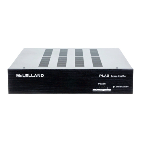
McLelland PLA2 User manual

McLelland
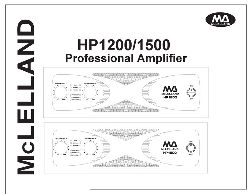
McLelland HP1200 User manual

McLelland
McLelland AVD-800P User manual

McLelland
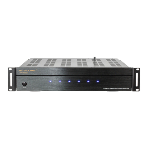
McLelland MAP-1200EW User manual

McLelland
McLelland AVD-800P User manual

McLelland
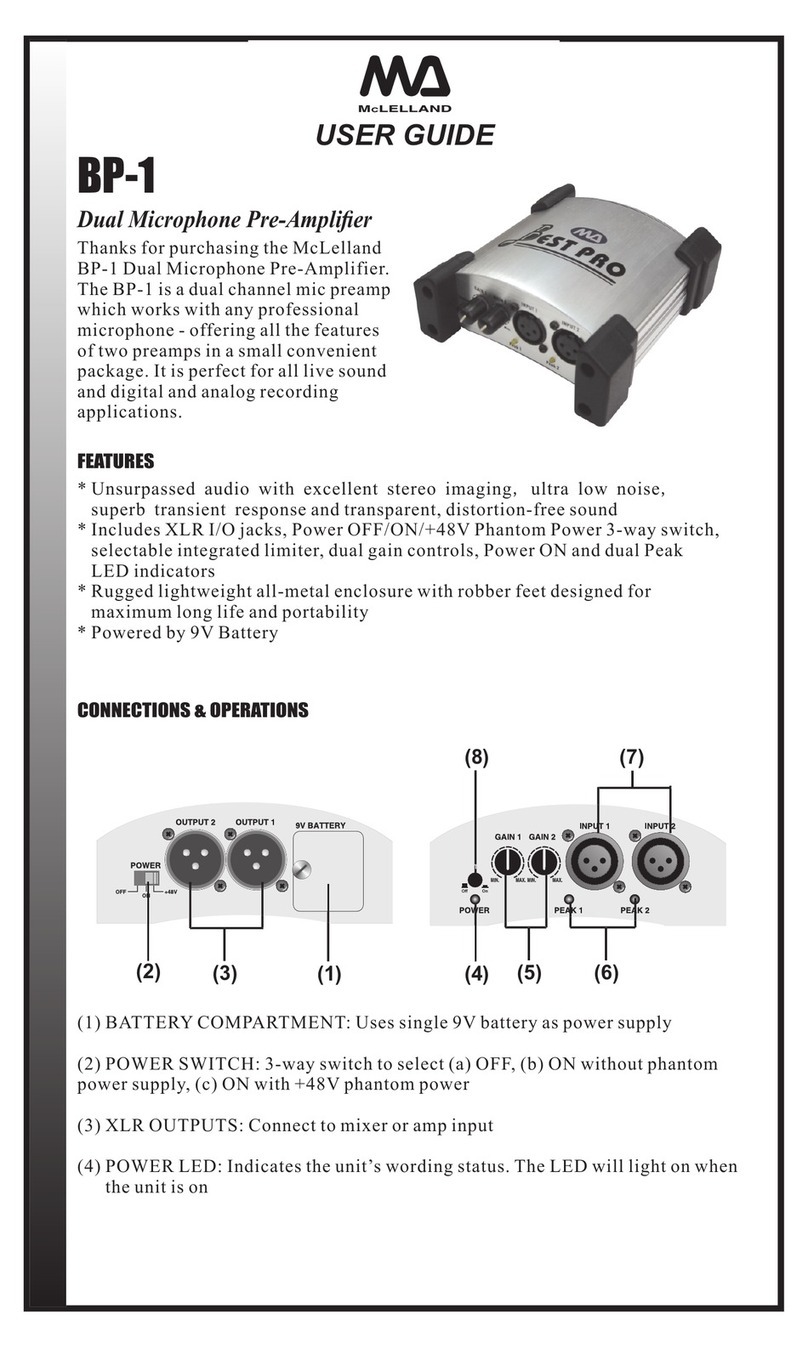
McLelland BP-1 User manual

McLelland
McLelland MAP 1200 User manual

McLelland
McLelland PLA2FX User manual