McNeilus 1487747 Guide

SSV Extreme 9” Monitor
Operation, Service, & Parts
© 2014 McNeilus Truck and Manufacturing, Inc.
Rev. 1216
Monitor P/N: 1487747
Manual P/N : 1489226

Street Smart Vision Systems
Extreme Monitor/DVR System
Extreme 9" Monitor/DVR System© 2014 McNeilus Truck and Manufacturing, Inc.
Disclaimer:
This manual must not be used to repair your vehicle. Repair information is available by calling McNeilus Customer Service at
(888) 686-7278.
The information in this Manual will be your guide to operation, service, and basic maintenance for this equipment.
A
ll information, illustrations, and specifications in this manual are based on the information available at the time this manual was
published.
The illustrations used in this manual are intended as representative reference views only. Because of our continuous
product improvement policy
, we may modify information, illustrations, and/or specifications to explain and/or exemplify a produ
ct,
service, or maintenance improvement.
We reserve the right to make any change at any time without notice. Go to
www
.streetsmartparts.com for current information.
No part of this publication may be reproduced by any means - graphic, electronic, or mechanical, including photocopying,
recording, taping, or information storage and retrieval systems for any use or purpose - without the written permission of
McNeilus
Truck and Manufacturing, Inc.

Extreme 9" Monitor/DVR System © 2014 McNeilus Truck and Manufacturing, Inc.
Table of Contents
FOREWORD 1
Purpose of the Manual .............................................................................................................................. 1
Scope of the Manual ................................................................................................................................. 1
Parts and Service Locations...................................................................................................................... 2
Corporate Headquarters............................................................................................................................ 2
SAFETY 3
Important Safety Information ..................................................................................................................... 3
Operation Precautions............................................................................................................................... 3
Federal Communications Commission (FCC) Statement ......................................................................... 3
COMPONENT FEATURES 4
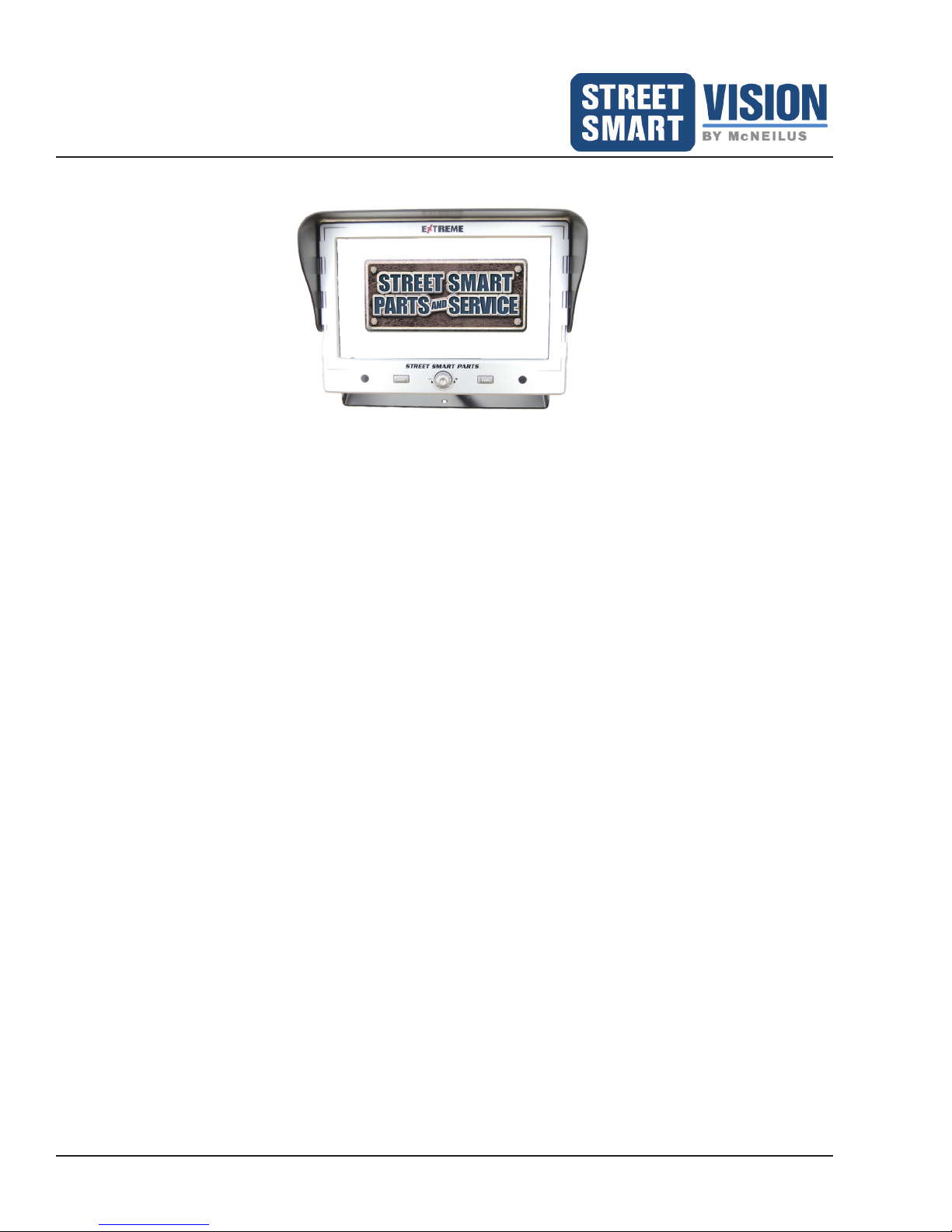
Monitor Features 9" Part Number 1487747............................................................................................... 4
Camera Features ...................................................................................................................................... 5
INSTALLATION 6
Basic Installation for Monitor 9" and its Components ..........................................................................7
Monitor 9" Kit Parts List ........................................................................................................................ 7
Monitor and GPS Receiver Installation................................................................................................. 7
Master Cable Harness.......................................................................................................................... 8
Power Accessory Harness.................................................................................................................... 9
Camera Connection Pin Assignment.................................................................................................... 10
Connection Diagram............................................................................................................................. 10
Monitor 9" Functions.......................................................................................................................... 11
Front Panel Buttons and System Start-Up ................................................................................................ 11
Power ................................................................................................................................................... 11
Jump..................................................................................................................................................... 11
Menu..................................................................................................................................................... 11
(+) ......................................................................................................................................................... 11
(-) .......................................................................................................................................................... 11
OSD MAIN MENU FUNCTIONS 11
Remote Control for OSD Menu Functions................................................................................................. 12
Typically Used Remote Control Buttons............................................................................................... 12
Access OSD Menu with Remote Control.............................................................................................. 12
MAIN MENU FUNCTIONS 13
On Screen Display Menu Options ............................................................................................................. 13
Input Source ......................................................................................................................................... 14
Camera............................................................................................................................................ 14
DVR ................................................................................................................................................. 14
Screen Settings .................................................................................................................................... 15
LCD Setup ....................................................................................................................................... 15
Mode................................................................................................................................................ 15
Dimmer ............................................................................................................................................ 15
Camera Settings................................................................................................................................... 16
Mirror ............................................................................................................................................... 16
Jump Setup...................................................................................................................................... 16
Trigger Setup ................................................................................................................................... 16
Auto Scan Time ............................................................................................................................... 17
Camera System............................................................................................................................... 17
Rear Grid Setting............................................................................................................................. 18

Extreme 9" Monitor/DVR System© 2014 McNeilus Truck and Manufacturing, Inc.
Table of Contents
Motion (Motion Detection)................................................................................................................ 23
Motion Sensitivity............................................................................................................................. 23
DVR Main Menu Options...................................................................................................................... 24
DVR Status...................................................................................................................................... 24
Audio Record Source....................................................................................................................... 24
DVR Record Source ........................................................................................................................ 25
DVR Time Out.................................................................................................................................. 25
DVR Menu/Remove SD................................................................................................................... 25
Mute Icon.............................................................................................................................................. 29
General Setup ...................................................................................................................................... 29
Language......................................................................................................................................... 29
Ignition Off Setup............................................................................................................................. 30
Menu Alert (Beep)............................................................................................................................ 30
Factory Defaults............................................................................................................................... 30
Passcode.............................................................................................................................................. 31
Exit........................................................................................................................................................ 31
SSV ANALYTICS SOFTWARE 32
SSV Analytics Software Screenshot.......................................................................................................... 32
CAMERA AND CABLE INSTALLATION 34
Camera and Cable Installation ..........................................................................................................35
Front End Loader ...................................................................................................................................... 36
Rear End Loader ....................................................................................................................................... 37
AutoReach................................................................................................................................................. 38
Zero Radius............................................................................................................................................... 39
Mixer.......................................................................................................................................................... 40
Camera Bracket Illustrations ..................................................................................................................... 41
TROUBLESHOOTING 43
Troubleshooting Chart ............................................................................................................................... 43
COMPONENTS FOR INDIVIDUAL SALE 46
Selected Component Images .................................................................................................................... 48
COMPONENT SPECIFICATIONS 51
Monitor Specications for P/N 1487747 .................................................................................................... 51
Camera Specications for P/N 1470028 ................................................................................................... 52
PRECO PREVIEW RADAR SYSTEM 53
Preco ElectronicsTM PreView® Radar Systems.................................................................................53
PreView®Single Sensor System for P/N 1479540 (For Front and Side Loader Applications Only) ..... 53
Installation Instructions.............................................................................................................................. 53
PreView®Single Sensor System for P/N 1504244 (For Rear Loader Application Only)......................... 58
Installation Instructions.............................................................................................................................. 58
PreView®Dual Sensor System for P/N 1474028 ........................................................................................ 63
Installation Instructions.............................................................................................................................. 63
HARDWARE WARRANTY 69

Extreme 9" Monitor/DVR System © 2014 McNeilus Truck and Manufacturing, Inc.
1
Foreword
Purpose of the Manual
This manual provides safety, parts information, installation, operation, troubleshooting, monitor and camera
specications, and camera mounting for the Extreme Monitor/DVR System manufactured by McNeilus Street
Smart Parts and Service.
The information in this manual will be your guide to operation and maintenance for this equipment.
Scope of the Manual
This manual provides information for use by the equipment operator and service personnel under the following
headings:
• Safety
• Parts List
• Installation
• Operation
• Camera Installation and Mounting Locations
• Troubleshooting
• Individual Component Sales
• Monitor and Camera Specications
• Preco ElectronicsTM PreView® Radar Systems
• Warranty
To order a free replacement manual, contact the McNeilus Street Smart Parts and Service at 888-686-7278 or
visit www.streetsmartparts.com to download a free PDF copy.

Extreme 9" Monitor/DVR System© 2014 McNeilus Truck and Manufacturing, Inc. 2
Foreword
Parts and Service Locations
Contact your McNeilus Street Smart Parts and Service location to order parts, receive service information, or for
other assistance. Contact by phone or visit www.streetsmartparts.com. We have factory owned parts and service
centers near you.
Phone Number 888-686-7278
State City
AZ Phoenix
CA Colton
CA Stockton
CO Denver
CT East Granby
FL Miami
FL Tampa
GA Villa Rica
IL Sugar Grove
IN Fort Wayne
LA New Orleans
MD Beltsville
MN Dodge Center
MO North Kansas City
NC High Point
NV Las Vegas
NY Bronx
OH Cincinnati
OH Columbus
PA Morgantown
TX Houston
TX Hutchins
UT West Valley City
WA Puyallup
WI Oshkosh
Canada
Ontario and Western Provinces 800-265-1089
Quebec and Maritime Provinces 800-996-4937
Corporate Headquarters
Contact McNeilus Street Smart Parts and Service directly at our corporate headquarters at the following address,
phone numbers, and website address:
McNeilus Street Smart Parts and Service
615 East Hwy. Street
Dodge Center, MN 55927
Telephone: 507-374-6321 Website: www.mcneiluscompanies.com
Parts Toll Free: 1-888-686-7278 Parts Website: www.streetsmartparts.com

Extreme 9" Monitor/DVR System © 2014 McNeilus Truck and Manufacturing, Inc.
3
Safety
Important Safety Information
Read and understand this entire manual before operating, repairing, or adjusting your McNeilus
equipment.
Those who use and maintain this equipment must be thoroughly trained and familiar with the product.
If incorrectly used or maintained, this equipment can cause severe injury.
Always keep this manual in a location where it is readily available for persons who operate or maintain the
product. Additional copies of this manual are available from McNeilus®Street Smart Parts and Service™ for no
charge. Please contact your McNeilus parts and service location to order parts, additional manuals, or if you
have any questions about the information in this manual, this product, or safe operating procedures.
THESE SAFETY PROCEDURES ARE FOR YOUR OWN PROTECTION.
Do not operate this equipment until you have read its contents thoroughly. Please contact McNeilus Truck and
Manufacturing, Inc. if you require assistance.
Should operators of this equipment have a reading or
learning disability, dyslexia, or other such condition, they
must be assigned a mentor/trainer to read and explain
to them the entire contents of this manual as well as the
safety guidelines, danger, caution, and warning decals on
this unit. Such individuals should not be allowed to operate
this equipment until they thoroughly understand all of these
materials. Failure to do so can result in serious injury or
death.
Safety and safe working procedures must be followed at all times.
Operation Precautions
1. Before you begin driving, ensure the monitor controls are adjusted properly to help avoid unnecessary
distractions while driving.
2. Before you begin driving, conrm the view provided by the camera is sufcient for your needs. Adjustments
to the camera viewing angles should be made before you begin driving.
3. Before you begin driving, determine that the orientation of the image on the monitor is proper. For example,
cameras should produce a mirror image, meaning items on the left side of the vehicle will appear on the left
side of the monitor.
4. Do not let the Extreme Monitor/DVR System distract you from driving safely.
Federal Communications Commission (FCC) Statement
This equipment has been tested and found to comply with the limits for a Class B Digital Device, pursuant to Part
15 of the FCC Rules.
SAFETY NOTICE
Perform your company’s Lockout/Tagout
procedure. If your company does not have a
Lockout/Tagout procedure, follow OSHA
1910.147 and 1910.146 Confined Space as
appropriate.

Extreme 9" Monitor/DVR System© 2014 McNeilus Truck and Manufacturing, Inc. 4
Component Features
Monitor Features 9" Part Number 1487747
• 9 inch color high resolution, crystal clear display
• Professional metal case with Certied Anti-Shock
Design up to 15G
• Touchscreen capable
• Advanced On Screen Display (OSD) Menu for
easy navigation
• Supports single/dual/triple/quadruple viewing
options
• OSD control for individual normal/mirror camera
image
• Built-in DVR system (SD Card type)*
• Locking SD Card Cover
• Supports up to ve (5) camera inputs with
waterproof connectors
• Auto Sense technology adds and removes
cameras for faster installation
• Camera triggering wire used to activate individual
cameras or camera combinations
*File format of the SD Card is Windows
compatible.
SD Card Not Included, but is available for purchase
through McNeilus®Street Smart Parts and
Service™. P/N 1453457 for a 32 GB SDHC Card.
The 32 GB SDHC size SD Card is the largest
capacity size that the DVR can use. Do not use a
SD Card larger than 32 GB.
• Distance Grid
• Backlighted buttons
• LCD
• Night brightness modes
• GPS for Analytics with external antenna
• Provides 1 video / 1 audio signal output
• 30 frames per second recording
• Standby recording with the LCD screen
turned off
• Motion Detection Surveillance while camera
is in idle mode
• Dimmer control: Off position or 1-9 different
position controls
• Supports English, French, and Spanish
• Auto detection for NTSC / PAL systems
• Support 10V-36V DC Power Supply
• Extra shielded cabling to help prevent
electrical, engine, and RF interference

Extreme 9" Monitor/DVR System © 2014 McNeilus Truck and Manufacturing, Inc.
5
Component Features
Camera Features
Part Number 1470028
• 720P all digital resolution
• High Denition
• 140° wide angle
• IP69K code - waterproof and dust proof rating
• 12 LEDs
• Certified Anti-Shock Design up to 20G
• Automatic or manual night vision adjustment
• Up to 100 feet of night vision distance
• Bracket mounted
• Image sensor: IR and Color
• Operating temperature of -67°F to 158°F
• Adjustable IR from off, high, medium, medium-
low, low positions
• Mirror image capable by removal of threaded plug
located on the back of the camera
• Automatic heat chip set
• Microphone / audio capable
NOTE
Remove the threaded plug on the back of the
camera to mirror the image on the screen. The
DVR will record a mirrored image.
NOTE
The adjustable IR button is used to adjust the
intensity of the IR for night vision. Patent Pending.
Front View of Camera
Mirror Image Plug
Adjustable IR Button
Back View of Camera
NOTE
If a forward drive facing camera is used in the cab,
the IR must be turned off.
To do this:
1. Turn on the camera image on the monitor.
2. Place your hand in front of the camera so it is
viewed on the monitor.
3. Keep pressing the IR button on the back of the
camera until the view of your hand goes black
on the monitor. The IR is now turned off.

Extreme 9" Monitor/DVR System© 2014 McNeilus Truck and Manufacturing, Inc. 6
Installation
Monitor 9"
1487747
Installation and
Menu and DVR Functions

Extreme 9" Monitor/DVR System © 2014 McNeilus Truck and Manufacturing, Inc.
7
Installation
Basic Installation for Monitor 9" and its Components
Monitor 9" Kit Parts List
Item Description Quantity
1 9” LCD Monitor (P/N 1487747) 1
2 Sun Shield 1
3 Mounting Bracket 1
4 Screws 4
5 Remote Control (P/N 1476860) 1
6 Triangle Bit Driver (P/N 1484556) 1
7 Power Accessory Harness (P/N 1511546) 1
8 SD Card Lock Cover (with 2 screws) 1
9GPS Antenna 1
Monitor and GPS Receiver Installation
READ AND UNDERSTAND THESE INSTALLATION INSTRUCTIONS BEFORE INSTALLING THE MONITOR
AND CABLES.
Follow all Lockout/Tagout instructions during installation of the Monitor and its equipment.
Install the monitor in the vehicle's cab, either overhead or on the dashboard, and within three feet of the driver.
(For a dual drive vehicle, the monitor must be mounted where it is accessible from both the left side and right
side driving positions.)
1. In the cab, located an area that best accommodates the monitor and the driver's view of it. Make sure the
monitor will not obstruct any part of the driver's view for driving and operation. It is recommended
to place the monitor on a metal surface, or in cases where the surface is plastic, support plates may be
required.
2. Use the provided mounting bracket as a template for drilling the holes that hold the monitor in place. Verify
the area around and underneath being drilled into is clear of all wires or other items. Drill the holes. NOTE:
If the provided bracket does not allow for positioning the monitor in the best location for the driver's view,
see Page 46 for other bracket options available through McNeilus Parts at 888-686-7278 or www.
streetsmartparts.com. If you require a different bracket for the monitor, use that bracket as a template for
drilling the holes.
NOTE: McNeilus offers various monitor mounting hardware (RAM®Mount products) for purchase, see
Page 46. McNeilus recommends using P/N 1476231 mount with one of the three possible double socket
clamps (P/N 1476232, 14789033, 14789034), see Page 46 for specic descriptions. When using this
system, it is recommended to use Blue #2 Loctite on the bolts to attach the RAM Mount ball to the back of
the monitor.
3. Mount the bracket using the vibration pad with the appropriate hardware. The vibration pad is placed
between the mounting surface and the monitor mounting bracket. Hardware is not provided.
4. Before placing the monitor on the bracket, locate the four wires on the monitor from the Power Accessory
Harness: Power (red), Reverse (green), Ground (black), Battery or constant power source (yellow). See
Page 9 for more information on connecting these wires.
a. Connect the ground wire (black) to a solid chassis ground.
b. Connect the power wire (red) to an ignition power source.
c. Connect the battery wire (yellow) to constant power source or to the battery.

Extreme 9" Monitor/DVR System© 2014 McNeilus Truck and Manufacturing, Inc. 8
Installation
d. Connect the reverse wire (green) to the reverse light circuit. When connected properly, this wire allows
the monitor system to come on when the vehicle is placed in reverse.
e. Connect the power accessory harness to the power socket on the rear side of the monitor.
5. Bolt the monitor in the bracket, and adjust the position as needed for the driver's view.
6. Clip the provided sun shield onto the monitor using the provided hardware, if desired.
7. Connect the GPS antenna to the Master Cable Harness.
8. Attach the GPS receiver on the dash or on the inside cab windshield in clear reception of satellites. The
receiver is magnetized for attaching, or it may be attached with a piece of Velcro.
Master Cable Harness
CAMERA A
CAMERA B
CAMERA C
CAMERA D
CAMERA E
GPS
Antenna
Wire Function Note
BROWN (Color Wire 4 Pin Connector) CAMERA A For Backup / Reverse Camera Connect
PURPLE (Color Wire 4 Pin Connector) CAMERA B For Left Camera Connect
BLACK (Color Wire 4 Pin Connector) CAMERA C For Right Camera Connect
GRAY (Color Wire 4 Pin Connector) CAMERA D For Driver / Facing Forward Camera Connect
BLACK (Color Wire 4 Pin Connector) CAMERA E For Front / Hopper Connect
GPS ANTENNA CONNECTOR GPS To connect the GPS Antenna to the monitor

Extreme 9" Monitor/DVR System © 2014 McNeilus Truck and Manufacturing, Inc.
9
Installation
Power Accessory Harness
Part number for the Power Accessory Harness is 1511546.
RED
BLACK
YELLOW
GRAY
BLUE
GREEN
PURPLE
BROWN
GND
PWR
Left
Front
Park
Battery
Reverse
Right
Wire Function Note
RED ACC POWER Connect to Ignition Power Source.
BLACK GROUND Connect directly to the battery ground or to a good chassis ground.
YELLOW BATTERY
Connect to the battery or a constant power source to ensure your monitor
settings do not reset if the monitor is turned off for an extended period of time.
And/or will allow the DVR system to operate when LCD screen is off (see
Ignition Set Up, Page 30).
NOTE: The following wires only need to be used if you desire the camera to display when the vehicle is in a specic
operation (e.g., Reverse).
GREEN REVERSE / BACK UP
(CAMERA A)
If you want this camera to be activated and displayed when the truck is in
Reverse, connect the Green wire to a Reverse/Back Up signal.
PURPLE LEFT TURN
(CAMERA B)
If you want this camera to be activated and displayed when the Left Direction
Turn Signal is activated, connect the Purple wire to the directional signal Left.
BROWN RIGHT TURN
(CAMERA C)
If you want this camera to be activated and displayed when the Right Direction
Turn Signal is activated, connect the Brown wire to the directional signal Right.
BLUE FRONT / HOPPER
(CAMERA D)
If you want this camera to be activated and displayed when the truck is in
Drive, connect the Blue wire to a Power signal.
GRAY PARK
(CAMERA E)
If you want this camera to be activated and displayed when the truck is in Park,
connect the Gray wire to a Park signal.
NOTE: When a trigger wire is activated, that camera takes precedence over all other recording options for the period of
time that the trigger wire is activated.
NOTE: Using a directional turn signal to activate a camera will require the use of the 2-second off delay module (P/N
1452176).

Extreme 9" Monitor/DVR System© 2014 McNeilus Truck and Manufacturing, Inc. 10
Installation
Camera Connection Pin Assignment
41
32
Image displays the pin
assignment from the monitor
side to the camera connector.
Pin Assignments:
Pin 1 = GND (Ground)
Pin 2 = +12V (Power)
Pin 3 = Video
Pin 4 = Audio
Connection Diagram
Power
Accessory
Harness
Master
Cable
Harness
CAMERA A REVERSE
CAMERA B LEFT
CAMERA C RIGHT
CAMERA D FRONT
CAMERA E PARK
GPS ANTENNA CONNECTION
RED for ACC to connect to Ignition Power Source
BLACK for Ground
YELLOW for connection to Battery
GREEN for connection to trigger Camera A
PURPLE for connection to trigger Camera B
BROWN for connection to trigger Camera C
BLUE for connection to trigger Camera D
GRAY for connection to Camera E
NOTE
The yellow wire must be connected to the battery
or a constant power source to ensure your monitor
settings are retained and also to allow certain
recording options to function when the LCD screen
is turned off (see Ignition Off Setup).

Extreme 9" Monitor/DVR System © 2014 McNeilus Truck and Manufacturing, Inc.
11
OSD Main Menu Functions
Monitor 9" Functions
Front Panel Buttons and System Start-Up
Use the buttons on the Front Panel for the following functions:
Power
Turns the monitor ON or OFF. Also checks software version by holding down for 1 second.
Jump
Allows the screen image to “jump” or alternate between Jump 1 camera setup and Jump 2 camera setup. See
Page 16 for set up of Jump function.
Menu
Provides the following selection:
• Press and hold this button/knob until the On Screen Display (OSD) Menu displays
• In the OSD Menu, this button/knob also acts as the “enter or exit” function in specic congurations to
change and save the congurations
• Lightly press the Menu button/knob to switch the screen image to the next image available
(+)
Navigates upward/ to the right in the OSD Menu and adjusts the volume up on the monitor’s speaker.
(-)
Navigates downward/ to the left in the OSD Menu and adjusts the volume down on the monitor’s speaker.
Figure 1: Front Panel buttons and On Screen Display (OSD) Main Menu
Jump Button Power Button
Menu Button/ Knob
Navigation

Extreme 9" Monitor/DVR System© 2014 McNeilus Truck and Manufacturing, Inc. 12
OSD Main Menu Functions
Remote Control for OSD Menu Functions
This system comes with a remote control.
• The remote control functions as a secondary operational tool when in the OSD or DVR menus (the
touchscreen is the primary operational tool for the menus)
Typically Used Remote Control Buttons
• Press MENU to display the OSD Menu
• Press DVR to see what is currently set for DVR
• Press MUTE to silence the speaker on the monitor
• Press SOURCE to page through all camera view combinations (A+B,
D(B+C), etc.) and to view DVR
• Press JUMP to “jump” or alternate views between Jump 1 camera
setup and Jump 2 camera setup. See Page 16 for set up of
Jump.
• Press VOL + to adjust the volume on the monitor’s speaker
• Press VOL ―to adjust the volume on the monitor’s speaker
• Press Up Arrow to navigate through the OSD menu
• Press Down Arrow to navigate through the OSD menu
• Press Stop/Return to exit the OSD menu
The following buttons on the Remote Control are not currently used for any applications.
• Pair
• Ch/Set
• Privacy
• VGA/QVGA
• CH+ or CH-
Access OSD Menu with Remote Control
When using the Remote Control,
• Press the MENU button to enter the OSD Main Menu. Do Not use the OSD button on the Remote Control.
• In the menu mode, navigate to a function by pressing the Up Arrow and Down Arrow buttons.
• Press ENTER to select a function when in the OSD Menu.
MUTE JUMPVIDEO
ENTER
MENU
CH +
REC
CH -
VOL +
VOL -
PAIR
SOURCE
OSD
DVR
STOP
RETURN
VGA
QVGA
PRIVACY
CH
SET

Extreme 9" Monitor/DVR System © 2014 McNeilus Truck and Manufacturing, Inc.
13
Main Menu Functions
On Screen Display Menu Options
Press MENU on the Front Panel Buttons to display the On Screen Display (OSD) Main Menu.
For Input Source settings, see Page 14.
For Screen Settings, see Page 15.
• LCD - Page 15.
• Mode - Page 15.
• Dimmer - Page 15.
For Camera Settings, see Page 16.
• Mirror - Page 16
• Jump Setup - Page 16
• Trigger Setup - Page 16
• Auto Scan Time - Page 17
• Camera System - Page 17
• Rear Grid Setting - Page 18
• Motion - Page 23
• Motion Sensitivity - Page 23
For DVR Settings, see Page 24.
• DVR Status - Page 24
• Audio Record Source - Page 24
• DVR Record Source - Page 25
• DVR Time Out - Page 25
• DVR Menu - Page 25
For Mute Settings, see Page 29.
For General Setup, see Page 29.
• Language - Page 29
• Ignition Off Setup - Page 30
• Menu Alert - Page 30
• Factory Defaults - Page 30
For Passcode Setup, see Page 31.
To Exit the OSD, see Page 31.
NOTE
The OK button MUST be pressed to accept/save
changes to settings.
NOTE
Choose the EXIT function to exit from the menu level
that you were just in. Choose EXIT on the OSD Main
Menu to exit from the entire OSD Menu. The automatic
exit function exits you from the OSD Menu after
approximately 10 seconds of inactive use.

Extreme 9" Monitor/DVR System© 2014 McNeilus Truck and Manufacturing, Inc. 14
Main Menu Functions
Input Source
Displays the options for video input (Figure 2).
• Camera
• Displays what is currently showing for each camera.
• DVR
• In DVR view, screen will display the camera views that are currently being recorded. Any changes to
DVR settings must be completed in the DVR menu, DVR Record Source.
NOTE: Shown is the screen without any cameras selected to record.
Figure 2: Camera Settings and DVR Settings.
NOTE
The OK button MUST be pressed to accept/save
changes to settings.

Extreme 9" Monitor/DVR System © 2014 McNeilus Truck and Manufacturing, Inc.
15
Main Menu Functions
Screen Settings
• LCD Setup
• Brightness (recommended value is 16)
• Contrast (recommended value is 16)
• Color (recommended value is 16)
• Tint (recommended value is 16)
• Sharpness (recommended value is 30)
• Mode - (recommended value is 16:9)
• Dimmer
Figure 3: Screen Settings Menu and LCD Setup.

Extreme 9" Monitor/DVR System© 2014 McNeilus Truck and Manufacturing, Inc. 16
Main Menu Functions
Camera Settings
Enters the functions for camera set up. The system can hold a maximum of four (4) cameras.
• Mirror - reverse image shown left to right or right to left (if you want the mirror image to appear correctly in
the DVR recording, you will need to either A. change the camera mirror setting to ON (press OK to save the
change) or B. remove the threaded plug off the back of the camera. See Page 5 for more details) (Figure
4).
• Jump Setup - sets up the Jump function to “jump” or alternate among selected cameras (Figure 4). Allows
for a Jump 1 selection and a Jump 2 selection.
• Single video image, dual images, triple images, quadruple (quad) images, and DVR function
• In single video view, screen will display only one (1) channel image at a time (A, B, C, D)
• In dual video view, screen will display two (2) channel combination views such as A+B, A+C, A+D, B+C
• In triple video view, screen will display the combinations of A+(B+C), D+(B+C), (B+C)+A, (B+C)+D
• In quad video view, screen will display four (4) channel combination views at one time (A+B+C+D)
• NOTE: Cameras D and E are toggle cameras. You cannot view cameras D and E at the same time.
Figure 4: Mirror and Jump screens in the Camera Settings.
Jump 1 and Jump 2 screens.
• Trigger Setup - telling the monitor which image/camera(s) to display when a particular trigger wire is activated.
This set up is for the camera signied in the menu, plus any additional cameras you want to display, up to
four cameras. Distance grid function is only available if selecting the single camera conguration (Figure 4).
• Trigger Record: Select ON if you want the triggered camera to record when it appears on the screen.
Figure 5: Trigger Setup Main Menu and Trigger Setup for Camera (A).
Table of contents
Other McNeilus Monitor manuals