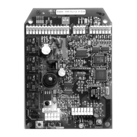
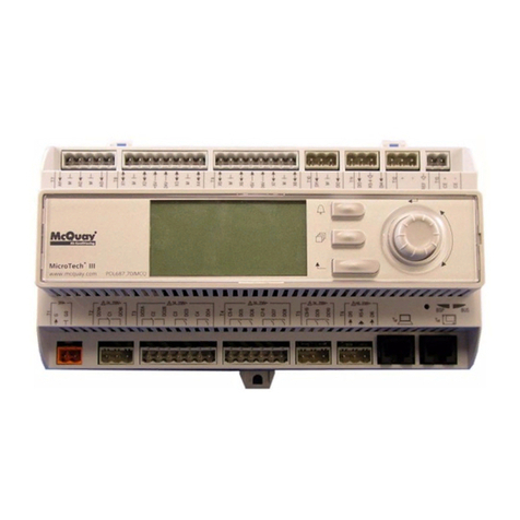
McQuay MicroTech II Instruction Manual

© 2004 McQuay International
MicroTech™ II
Vertical Self-Contained Systems Unit Controller
• Used with McQuay models: SWP and SWT
Installation and Maintenance IM-710-1
Group: Applied Systems
Part Number: IM710-1
Date: June 2004
Supersedes: IM710-0

Contents
McQuay and MicroTech II are registered trademarks of McQuay International.
Microsoft is a registered trademark of Microsoft Corporation.
Windows is a trademark of Microsoft Corporation.
Copyright © 2004 McQuay International. All rights reserved throughout the world.
Introduction . . . . . . . . . . . . . . . . . . . . . . . . . . . . . . . . . . . . . . . 1
General Description . . . . . . . . . . . . . . . . . . . . . . . . . . . . . . . 2
Component Data . . . . . . . . . . . . . . . . . . . . . . . . . . . . . . . . . . . . . . . 2
Main Control Board (MCB) . . . . . . . . . . . . . . . . . . . . . . . . . . . 3
Analog inputs terminal blocks . . . . . . . . . . . . . . . . . . . . . 4
Binary Inputs Terminal Blocks . . . . . . . . . . . . . . . . . . . . . 4
Binary Outputs Terminal Blocks . . . . . . . . . . . . . . . . . . . 4
RS-485 Communications Terminal Block . . . . . . . . . . . . 4
Power Supply Terminals . . . . . . . . . . . . . . . . . . . . . . . . . 4
Keypad/LCD Display Connection . . . . . . . . . . . . . . . . . . 4
Communication Modules . . . . . . . . . . . . . . . . . . . . . . . . . . . . . 4
Plug-in BACnet/IP Communications Module . . . . . . . . . . 4
Plug-in BACnet MS/TP Communications Module . . . . . . 4
LonWorks® Communication Modules . . . . . . . . . . . . . . . 5
RS-232 Connection Port . . . . . . . . . . . . . . . . . . . . . . . . . 5
15 VDC Supply Connection . . . . . . . . . . . . . . . . . . . . . . . 5
Main Control Board LEDs . . . . . . . . . . . . . . . . . . . . . . . . 6
Auxiliary Control Boards (CCB1and CCB2) . . . . . . . . . . . . . . 6
Analog Inputs Terminal Block (J8) . . . . . . . . . . . . . . . . . 7
Binary Inputs Terminal Blocks (J9 and J10) . . . . . . . . . . 7
Binary Outputs Terminal Block . . . . . . . . . . . . . . . . . . . . 8
RS-485 Communications Module . . . . . . . . . . . . . . . . . . 8
Power Supply Terminals (J1) . . . . . . . . . . . . . . . . . . . . . 8
J7 Terminal Block . . . . . . . . . . . . . . . . . . . . . . . . . . . . . . 8
J2 Terminal Block . . . . . . . . . . . . . . . . . . . . . . . . . . . . . . 8
Main Control Board (MCB) Output Relays and Triacs . . . . . . 8
Auxiliary Control Boards (CCB1 and CCB2) Output Relays . . 8
Keypad/Display . . . . . . . . . . . . . . . . . . . . . . . . . . . . . . . . . . . . 8
Temperature Sensors . . . . . . . . . . . . . . . . . . . . . . . . . . . . . . . 9
Pressure Transducers . . . . . . . . . . . . . . . . . . . . . . . . . . . . . . . 9
Humidity Sensors . . . . . . . . . . . . . . . . . . . . . . . . . . . . . . . . . . 9
Actuators . . . . . . . . . . . . . . . . . . . . . . . . . . . . . . . . . . . . . . . . . 9
Adjustable Frequency Drives (AFDs) . . . . . . . . . . . . . . . . . . . 9
Field Wiring . . . . . . . . . . . . . . . . . . . . . . . . . . . . . . . . . . . . . . . 10
Field Output Signals . . . . . . . . . . . . . . . . . . . . . . . . . . . . . . . . . . . 10
Outside Air Damper . . . . . . . . . . . . . . . . . . . . . . . . . . . . . . . . 10
Fan Operation Output . . . . . . . . . . . . . . . . . . . . . . . . . . . . . . 10
Remote Alarm Output . . . . . . . . . . . . . . . . . . . . . . . . . . . . . . 10
VAV Box Output . . . . . . . . . . . . . . . . . . . . . . . . . . . . . . . . . . 11
Cooling-Only Units . . . . . . . . . . . . . . . . . . . . . . . . . . . . 11
Cooling-Only Units With Field Supplied Heat . . . . . . . . 11
Units With Staged Heat . . . . . . . . . . . . . . . . . . . . . . . . . 11
Units With Modulating Heat . . . . . . . . . . . . . . . . . . . . . . 12
Pump Start Output . . . . . . . . . . . . . . . . . . . . . . . . . . . . . . . . . 12
Field Analog Input Signals . . . . . . . . . . . . . . . . . . . . . . . . . . . . . . . 12
Zone Temperature Sensor Packages . . . . . . . . . . . . . . . . . . 12
Zone Sensor Without Remote Setpoint Adjustment . . . 12
Zone Sensor With Remote Setpoint Adjustment . . . . . . 12
Tenant Override (Timed) . . . . . . . . . . . . . . . . . . . . . . . . . . . . 13
External Discharge Air Reset Signal . . . . . . . . . . . . . . . . . . . 13
Field Actuator Feedback . . . . . . . . . . . . . . . . . . . . . . . . . . . . 14
Field 100% OA Damper Actuator . . . . . . . . . . . . . . . . . . . . . 14
Humidity Sensors . . . . . . . . . . . . . . . . . . . . . . . . . . . . . . . . . 15
Humidity sensor—discharge air control (DAC) unit . . . . 15
Field Binary Input Signals . . . . . . . . . . . . . . . . . . . . . . . . . . . . . . . 16
Manual Cooling And Heating Enable . . . . . . . . . . . . . . . . . . 16
Cooling Enable . . . . . . . . . . . . . . . . . . . . . . . . . . . . . . . 16
Heating Enable . . . . . . . . . . . . . . . . . . . . . . . . . . . . . . . 16
Manual Unit Enable . . . . . . . . . . . . . . . . . . . . . . . . . . . . . . . . 16
External Time Clock Or Tenant Override . . . . . . . . . . . . . . . . 16
Miscellaneous Output Signals . . . . . . . . . . . . . . . . . . . . . . . . 16
Service Information . . . . . . . . . . . . . . . . . . . . . . . . . . . . . . . 17
Controller Inputs . . . . . . . . . . . . . . . . . . . . . . . . . . . . . . . . . . . . . . . 17
Analog Inputs—Main Control Board (MCB) . . . . . . . . . . . . . . 17
Analog inputs—Auxiliary Control Boards (CCB1 and CCB2) 19
Binary Inputs—Main Control Board (MCB) . . . . . . . . . . . . . . 19
Binary Inputs—Auxiliary Control Boards (CCB1 and CCB2) . 19
CCB1 and CCB2 . . . . . . . . . . . . . . . . . . . . . . . . . . . . . . 20
Controller Outputs . . . . . . . . . . . . . . . . . . . . . . . . . . . . . . . . . . . . . 21
Binary Outputs—Main Control Board (MCB) . . . . . . . . . . . . . 21
Binary Outputs—Auxiliary Control Boards (CCB1 and CCB2) .
22
CCB1 & CCB2 . . . . . . . . . . . . . . . . . . . . . . . . . . . . . . . . 22
2 Compressors—2 Stages . . . . . . . . . . . . . . . . . . . . . . . . . . . 22
3 Compressors—3 Stages . . . . . . . . . . . . . . . . . . . . . . . . . . . 23
4 Compressors—4 Stages . . . . . . . . . . . . . . . . . . . . . . . . . . . 23
3 Small Compressors & 1 Large Compressor—5 Stages . . . 23
2 Small Compressors & 2 Large Compressors—6 Stages . . 23
6 Compressors—6 Stages . . . . . . . . . . . . . . . . . . . . . . . . . . . 24
Software Identification and Configuration . . . . . . . . 25
Main Control Board (MCB) Configuration . . . . . . . . . . . . . . . . . . . 25
Main Control Board (MCB) Data Archiving . . . . . . . . . . . . . . . . . . 26
Keypad/Display Objects . . . . . . . . . . . . . . . . . . . . . . . . . . . . . . . . . 26
Typical Wiring Diagrams . . . . . . . . . . . . . . . . . . . . . . . . . 27
Test Procedures . . . . . . . . . . . . . . . . . . . . . . . . . . . . . . . . . . 35
Troubleshooting Main Control Board (MCB) . . . . . . . . . . . . . 35
MCB Battery . . . . . . . . . . . . . . . . . . . . . . . . . . . . . . . . . . 35
MCB Data Archiving . . . . . . . . . . . . . . . . . . . . . . . . . . . . 35
MCB “Cold” Reboot . . . . . . . . . . . . . . . . . . . . . . . . . . . . 35
MCB LED Power-Up Sequence . . . . . . . . . . . . . . . . . . . 36
MCB LED Startup Error Codes . . . . . . . . . . . . . . . . . . . 37
Battery Test . . . . . . . . . . . . . . . . . . . . . . . . . . . . . . . . . . 38
Flash CRC Tests . . . . . . . . . . . . . . . . . . . . . . . . . . . . . . 38
SRAM Test . . . . . . . . . . . . . . . . . . . . . . . . . . . . . . . . . . . . . . . 39
Communication Port Tests . . . . . . . . . . . . . . . . . . . . . . . 39
IP Register Test . . . . . . . . . . . . . . . . . . . . . . . . . . . . . . . 39
Troubleshooting Auxiliary Control Boards (CCB1and CCB2) 39
Hardware Check . . . . . . . . . . . . . . . . . . . . . . . . . . . . . . 39
RS-485 Communication Module Status LEDs . . . . . . . . 39
Troubleshooting Keypad/Display . . . . . . . . . . . . . . . . . . . . . . . . . . 40
Keypad/Display Power Up Initialization . . . . . . . . . . . . . 40
Troubleshooting Temperature Sensors . . . . . . . . . . . . . . . . . 41
. . . . . . . . . . . . . . . . . . . . . . . . . . . . . . . . . . . . . . . . . . . . . . . . 41
Troubleshooting Communications Cards . . . . . . . . . . . . . . . . 41
BACnet/IP Module . . . . . . . . . . . . . . . . . . . . . . . . . . . . . 42
BACnet MS/TP Module . . . . . . . . . . . . . . . . . . . . . . . . . 42
LonMark Module . . . . . . . . . . . . . . . . . . . . . . . . . . . . . . 42
Troubleshooting Static Pressure Transducers . . . . . . . . . . . . 42
Troubleshooting Refrigerant Pressure Transducers . . . . . . . 44
Parts List . . . . . . . . . . . . . . . . . . . . . . . . . . . . . . . . . . . . . . . . . 45

McQuay IM 710-1 1
Introduction
This manual contains information regarding the
MicroTech II™ control system used in the McQuay®
Vertical Self-Contained product line. It describes the
MicroTech II components, input/output configurations, field
wiring options and requirements, and service procedures.
For a description of operation and information on using the keypad
to view data and set control parameters, refer to the appropriate
program-specific operation manual, listed in Table 1 below. For
installation and commissioning instructions and general
information on a particular unit model, refer to its model-specific
installation manual in Table 2.
Table 1: Program-specific unit operation literature
Unit control configuration Operation manual bulletin number
Discharge air control (VAV or CAV) OM 711
Space comfort control (CAV-Zone Temperature control) OM 712
Table 2: Model-specific unit installation literature
Unit model Installation & maintenance data bulletin number
SWP (018 - 105) IM 708
SWT (018 - 040) IM 709
NOTICE
This equipment generates, uses, and can radiate radio frequency energy, and if not installed and used in accordance with
this instruction manual, may cause interference to radio communications. It has been tested and found to comply with the
limits for a Class A digital device, pursuant to part 15 of the FCC rules. These limits are designed to provide reasonable
protection against detrimental interference when the equipment is operated in a commercial environment. Operation of this
equipment in a residential area is likely to cause detrimental interference, in which case users will be required to correct the
interference at their own expense. McQuay International disclaims any liability resulting from any interference or for
the correction thereof.
WARNING
Electric shock hazard. Can cause personal injury or equipment damage.
This equipment must be properly grounded. Connections and service to the MicroTech II control panel must be performed
only by personnel knowledgeable in the operation of the equipment being controlled.
CAUTION
Extreme temperatures can damage system components.
The MicroTech II controller is designed to operate in ambient temperatures from -20°F to 125°F. It can be stored in ambient
temperatures from -40°F to 140°F. The controller is designed to operate in a 10% to 90% RH (non-condensing) and to be
stored in a 5% to 95% RH (non-condensing) environment.
CAUTION
Static sensitive components. A static discharge while handling electronic circuit boards can damage the
components.
Before performing any service work, discharge any static electrical charge by touching the bare metal inside the main control
panel. Never unplug any cables, circuit board terminal blocks, relay modules, or power plugs while power is applied to the
panel.

2McQuay IM 710-1
General Description
The MicroTech II Unit Controller is a microprocessor-based
controller designed to provide sophisticated control of
McQuay Vertical Self-Contained units. In addition to
providing normal temperature, static pressure, and
ventilation control, the controller can provide alarm
monitoring and alarm-specific component shutdown if
critical system conditions occur.
The operator can access temperatures, pressures, operating
states, alarm messages, control parameters, and schedules
with an 8-key keypad and a 4-line by 20-character display.
The controller includes password protection against
unauthorized or accidental control parameter changes.
This MicroTech II controller is capable of complete,
stand-alone unit control or it can be incorporated into a
building-wide network using an optional plug-in
communication module. Available communication modules
include BACnet Ethernet, BACnet MSTP, LonMark Space
Comfort Controller (SCC) and LonMark Discharge Air
Controller (DAC).
Component Data
The main components of the MicroTech II control system
include the main control board (MCB), either one or two
optional auxiliary cooling control boards (CCB1 and CCB2),
and a keypad/display. The MCB, CCB1 and CCB2 are
always located in the main control panel as shown in
Figure 1. These components are interconnected by shielded
multi-conductor communication cables, or in the case of the
keypad/display by a six conductor cable with an RJ-11 style
modular connector. Transformers T1, T2, and T3 supply
power to the system. The following are descriptions of these
components and their input and output devices.
Figure 1:Typical MicroTech II main control panel layout
LonWorks Communication Module*
BACnet Communication Module
Disconnect Switch
(Optional)
Power Block
Phase Voltage
Monitor
Transformer, Control Output, 24V, T3
Transformer, Control Output, 24V, T2
Transformer, Main Control, 115V, T1
Duct Static Pressure Sensor
Adjustable Frequency
Drive (Optional)
* Unit controller is LONMARK®certified with the LONWORKS®communication module.

McQuay IM 710-1 3
Main Control Board (MCB)
Figure 2 shows the main control board (MCB). It contains a
microprocessor that is programmed with the main
application code to control the unit. The MCB receives up to
16 analog and 16 binary inputs directly and up to 6 analog
and 12 binary inputs from each optional auxiliary control
board (CCB1, CCB2). Auxiliary control boards
communicate this data with the MCB via an RS-485
communication bus interface. The MCB controls its own 16
binary outputs and up to 9 binary outputs on each auxiliary
board based on the inputs
.
Figure 2:Main control board

4McQuay IM 710-1
Analog inputs terminal blocks
The MCB receives up to 16 analog input signals on 4
terminal blocks located on the left side of the board. From
top to bottom, analog inputs AI1 through AI4 are terminated
on the first terminal block, AI5 through AI8 on the second,
AI9 through AI12 on the third, and AI13 through AI16 on
the fourth. Each analog input has two terminals. The
terminals for AI1 are 1 and 1C, the terminals for AI2 are 2
and 2C, and so forth. Refer to “Analog Inputs-Main Control
Board (MCB)” on page 17 for details regarding analog
inputs.
Binary Inputs Terminal Blocks
The MCB receives up to 16 binary input signals on 3
terminal blocks located on the top of the board. From right to
left, binary inputs BI1 through BI6 are terminated on the first
terminal block, BI7 through BI10 on the second and BI11
through BI16 on the third. Refer to “Binary Inputs-Main
Control Board (MCB)” on page 19 for details regarding
binary inputs.
Binary Outputs Terminal Blocks
The MCB controls up to 16 binary outputs when controlling
the unit. The binary outputs either energize on-board
electromechanical relays (BO1 through BO4, BO11 and
BO12) or triacs (BO5 through BO10 and BO13 through
BO16).
The unit control devices are wired to these relays or triacs
through six output terminal blocks on the right side of the
MCB. From top to bottom binary outputs BO1 and BO2 are
terminated on the first terminal block, BO3 and BO4 on the
second, BO5 through BO7 on the third, BO8 through BO10
on the fourth, BO11 through BO13 on the fifth, and BO14
through BO16 on the sixth.
Each binary output has three terminals. The terminals for
BO1 are NO, 1, and NC, the terminals for BO2 are NO, 2,
and NC, and so forth. Each binary output lights an LED
when the output is active. Refer to “Binary Outputs-Main
Control Board (MCB)” on page 19 for details regarding
binary outputs.
RS-485 Communications Terminal Block
The MCB exchanges information with up to four optional
auxiliary control boards via the RS-485 communication bus
terminal block in the lower left corner of the MCB. This
terminal block has four terminals, three of which are labeled
REF, Minus, and Plus. These terminals connect the auxiliary
boards to the RS-485 communication bus to interface them
with the MCB.
Power Supply Terminals
Transformer T2 supplies 24 VAC power to the MCB on the
24V and COM terminals located at the upper right corner of
the MCB.
Some of the binary outputs on the MCB drive 24 VAC pilot
relays in the unit control circuit. 24 VAC to power these pilot
relays is provided from transformer T3, through the SRC 1-8
and SRC 9-16 terminals located at the upper right corner of
the MCB, and through the particular binary output contacts.
Note: Place the output jumper associated with these outputs
in the SRC position. For detailed information
regarding binary output jumpers, refer to “Binary
outputs—main control board (MCB)” on page 19.
Keypad/LCD Display Connection
The keypad is connected to the main control board via a six-
conductor cable connected to an RJ-11 style modular jack
located at the bottom of the MCB. This connects the keypad
to the RS-485 communication bus interface with the MCB.
Communication Modules
In systems that require networking, one of the following
communications modules can be installed.
Plug-in BACnet/IP Communications Module
A BACnet/IP Communication Module can be plugged into
the MCB in the port location shown in Figure 2 on page 3.
The BACnet/IP Communication Module is designed to be an
add-on module to the MCB for networking to Building
Automation and Control Network (BACnet) systems. It is a
plug-in module that can be attached to the MCB via a 36-pin
header. It
includes 4 locking stand-offs to securely attach it to the
board. The MicroTech II Vertical Self-Contained Unit
Controller meets the requirements of ANSI/ASHRAE 135-
2001 standard for BACnet/IP per Annex J of the standard
with a conformance level of 3.
For a detailed description and troubleshooting information
regarding this communications module, refer to installation
and maintenance bulletin IM 703, MicroTech II BACnet/IP
Communications Module. For details regarding BACnet
protocol data, refer to engineering data document, ED 15
061, MicroTech II Protocol Information Data for Vertical
Self-Contained Units.
A unit equipped with an optional BACnet/IP
Communication Module is connected to a BACnet/IP
network through an eight-position RJ-45 style modular jack
located on the bottom edge of the MCB. This connection is
shown schematically in Figure 3 on page 6.
Plug-in BACnet MS/TP Communications Module
A BACnet/MSTP Communication Module can be plugged
into the MCB in the port location (see Figure 2 on page 3).
The BACnet MS/TP Communication Module is designed to
be an add-on module to the MCB for networking to Building
Automation and Control Network (BACnet) systems. It is a
plug-in module that can be attached to the MCB via a 12-pin
header, and includes 4 locking stand-offs to securely attach it
to the board. It allows the MCB to inter-operate with systems
that use the BACnet Master Slave Token Passing (MS/TP)

McQuay IM 710-1 5
protocol with a conformance level of 3. The MicroTech II
Vertical Self-Contained Unit Controller meets the
requirements of ANSI/AHSRAE 135-2001 standard for
BACnet systems.
For a detailed description and troubleshooting information
regarding this communications card, refer to installation and
maintenance bulletin IM 704, MicroTech II BACnet MS/TP
Communications Module. For details regarding BACnet
protocol data, refer to engineering data document, ED
15061, MicroTech II Protocol Information Data for Vertical
Self-Contained Units.
A unit equipped with an optional BACnet MS/TP
Communication Module is connected to a BACnet MS/TP
network through terminals 128 (+), 129 (-) and 130 (REF) on
terminal block TB2 in the main control panel. These
terminals are factory wired to the BACnet MS/TP module
when the module is factory installed. When the module is
field-installed, the add on communication card kit includes a
wiring harness to be installed between terminals 128, 129
and 130 and the BACnet MS/TP module. This connection is
shown schematically in Figure 3.
LONWORKS®Communication Modules
A LONWORKS Communication Module can be plugged into
the MCB in the port location shown in Figure 2 on page 6.
This card provides LONWORKS network communication
capability to the MCB. It is a plug-in module that can be
attached to the MCB via a 12-pin header, and includes 4
locking stand-offs to securely attach it to the board.
For a detailed description and troubleshooting information
regarding this communications module, refer to installation
and maintenance bulletin IM 702, MicroTech II LONWORKS
Communications Module. For details regarding LONWORKS
protocol data, refer to engineering data document, ED15
061, MicroTech II Protocol Information Data for Vertical
Self-Contained Units.
There are two versions of this module available. One is the
LONMARK Space Comfort Controller (SCC)
Communications Module and the other is the LONMARK
Discharge Air Control (DAC) Communications Module.
Space Comfort Control (SCC) Module. The Space Comfort
Controller (SCC) Communication Module supports the
LONMARK Space Comfort Controller (SCC) profile Number
8500.
Discharge Air Control (DAC) Module. The Discharge Air
Controller (DAC) Communication Module supports the
LONMARK Discharge Air Controller (DAC) profile Number
8610.
A unit equipped with an optional LONWORKS Space Comfort
Controller (SCC) Communication Module or LONWORKS
Discharge Air Controller (DAC) Communication Module
can be connected to a LONWORKS network through terminals
128 (A), 129 (B) on terminal block TB2 in the main control
panel. These terminals are factory wired to the module when
the module is factory installed. When the module is
field-installed, the add on communication module kit
includes a wiring harness to be installed between terminals
128 and 129 and the module. This connection is shown
schematically in Figure 3.
RS-232 Connection Port
A PC loaded with MicroTech II Service Tool software can be
connected directly or via a telephone modem to the RS-232
communications port located on the bottom edge of the
MCB. This connection is shown schematically in Figure 3.
15 VDC Supply Connection
The two 15V terminals located above the analog input
terminals provide 15 VDC power. This power is not used in
the Vertical Self-Contained Controller application. This
power supply is limited to sourcing 30 mA.
CAUTION
This is an unregulated power supply. Do not use to feed
three-wire potentiometer inputs. Equipment damage can
result.

6McQuay IM 710-1
Figure 3:MCB communication interface
Main Control Board LEDs
There are a number of LEDs in various locations on the
MCB. These LEDs consist of three groupings. There are 16
Binary Input (BI) LEDs located in the upper left corner of
the MCB. These LEDs are lit when the corresponding
Binary Input is turned ON. For information regarding the
functions of the Binary Inputs refer to “Binary Inputs-Main
Control Board (MCB)” on page 19. There are 16 Binary
Output (BO) LEDs, one located next to each Binary Output
on the right side of the MCB. These LEDs are lit when the
corresponding Binary Output is turned ON. For information
regarding the functions of the Binary Outputs refer to
“Binary Outputs-Main Control Board (MCB)” on page 21.
There are 4 Miscellaneous LEDs. These LEDs provide error
code information and indication of activity on the various
communication channels. Table 3 lists these LEDs with their
functions.
Auxiliary Control Boards (CCB1and CCB2)
There are up to two optional auxiliary cooling control boards
(CCB1 and CCB2). Although the input and output functions
on the two boards are defined differently in software, the
boards are physically identical.
The CCB1 and CCB2 are used whenever a unit is equipped
with factory DX cooling (models SWP and SWT). The
CCB1 and CCB2 are not used on units equipped with chilled
water or no cooling.
A typical auxiliary control board is shown in Figure 4 on
page 7. This board receives up to 6 analog and 12 binary
inputs and exchanges information with the MCB via an
RS-485 communication bus.
Table 3: Main control board miscellaneous LEDs
Unit Terminal
Block TB2
BACnet-
MS TP COMM.
N2 +
N2 -
REF
LonMark
COMM.
+
-
522 (CLR)
523 (BLK)
524 (DRN)
522
523
COMM. MODULE
RJ-45
MODULAR
JACK
RS-232 PORT
(DB-9 MALE)
SERIAL COMM.
LOCATED ON
DEADFRONT
(DB-9 MALE)
BACnet
MS/TP
BACnet
IP
MAIN CONTROL BOARD (MCB)
SERVICE
TOOL
10 BASE-T STYLE CONNECTION
128
129
130
128
130
Unit Terminal
BACnet-
IP
MODULE
MODULE
A
B
LED function Location on MCB LED color
RS-485 bus activity indication (LED is ON when activity present on the RS-485 bus) Left of RS-485 port connector Green
RS-232 port Activity Indication (LED is ON when activity present at the RS-232 port) Left of RS-232 port connector Green
BACnet/IP port activity indication (LED is ON when activity present at the BACnet/IP Port) Left of BACnet/IP port connector Green
MCB Error Indication*
Right of BACnet/IP port connector Red
Off Blinking
Normal Battery low or defective
*Refer to “Troubleshooting Main Control Board (MCB)” on page 35.

McQuay IM 710-1 7
Figure 4:Auxiliary control board (CCB1 board shown)
Analog Inputs Terminal Block (J8)
The auxiliary control board receives up to six analog input
signals via the AI (J8) terminal block on the right side of the
board.
Note: Only analog input AI5 is used with factory DX
cooling applications. The other five AIs are not used
for Self-Contained and are not supported in the
application software. Refer to “Analog inputs—
Auxiliary Control Boards (CCB1 and CCB2)” on
page 19 for details regarding analog inputs.
Binary Inputs Terminal Blocks (J9 and J10)
The auxiliary control board receives up to 12 binary input
signals via the BI terminal blocks (J9 and J10) on the right
side of the board. BI1 through BI6 are located on terminal
block J9 and BI7 through BI12 are located on terminal block
J10. Refer to “Binary inputs—Auxiliary Control Boards
(CCB1 and CCB2)” on page 19 for details regarding binary
inputs.
(RS485)

8McQuay IM 710-1
Binary Outputs Terminal Block
The auxiliary control board includes nine binary output
relays (BO1 through BO9) that are energized based on
commands received from the MCB. These relays provide the
appropriate switching actions for the control devices that are
wired to them through the BO terminals on the left side of
the board. Refer to “Binary Outputs-Auxiliary Control
Boards (CCB1 and CCB2)” on page 22 for details regarding
binary outputs.
RS-485 Communications Module
Each auxiliary control board is equipped with a plug in
R-485 Communication Module. This module includes a 3
position terminal block with terminals labeled N2+, N2- and
REF. These terminals are wired to the “Plus,” “Minus,” and
REF terminals on the RS-485 communication terminal block
on the MCB. The auxiliary control board exchanges
information with the MCB via this interface.
Each auxiliary board RS-485 Communication Module
includes an 8-position dip switch assembly (SW1) for
addressing the board. Refer to Figure 4 on page 7. CCB1
must always be set to address 2 and CCB2 to address 3. This
is done by setting the switches on each of the auxiliary
control boards as indicated in Table 4. If the switches are not
set as indicated, the MCB will not communicate correctly
with the board and the auxiliary control board will not
function properly.
Power Supply Terminals (J1)
Transformer T3 supplies 24 VAC power to terminal block
J1, terminals 1 (24VAC) and 2 (COM) on the auxiliary
control board (CCB1 and CCB2).
J7 Terminal Block
The J7 terminal block located at the top of the auxiliary
control board is not used in this product application.
J2 Terminal Block
The J2 terminal block located between the J10 and J8
terminal block on the right side of the auxiliary control board
is not used in this product application.
Main Control Board (MCB) Output Relays
and Triacs
Binary outputs BO1 through BO4, BO11 and BO12 control
pilot duty Form C electromechanical relays mounted on the
the MCB. The output terminals of these relays are connected
to a set of binary output terminal blocks located on the right
side of the MCB. These relays are designed for Class 2
operation and to switch loads with any of the following
characteristics:
• 5VDC @ 10 mA minimum, 1 A maximum
• 30 VAC @ 2 A nominal, 10 A inrush
Binary outputs BO5 through BO10 and BO13 through BO16
control triacs mounted on the MCB. The output terminals of
these triacs are connected to a binary output terminal block
located on the right side of MCB. These triacs are designed
to switch loads with 20 mA minimum, 24 VAC @ 1 A
maximum (with a total load current from all triacs not to
exceed 2.8A,TBV)
Auxiliary Control Boards (CCB1 and
CCB2) Output Relays
Binary outputs BO1 and BO2 control high power Form A
electromechanical relays mounted on the auxiliary control
board. The output terminals of these relays are connected to
the binary output terminals located on the left side of the
auxiliary control board. These relays are designed to switch
loads with any of the following characteristics:
• 1 hp 120 VAC
• 25 A resistive @ 120 VAC
Note: For this product application, the two jumpers on the
board just below the upper left corner of the RS-485
Communication Module must both be placed on the
right-most pins. If these are not positioned correctly
the devices controlled by binary outputs BO1 and
BO2 will not function properly.
Binary outputs BO3 through BO5 and BO7 through BO9
control low power Form A electromechanical relays
mounted on the auxiliary control board. The output terminals
of these relays are connected to the binary output terminals
located on the left side of the auxiliary control board. These
relays are designed to switch loads with any of the following
characteristics:
• 1/10 hp 120 VAC
• 5 A resistive @ 120 VAC
Binary output BO6 controls one low power Form C
electromechanical relay mounted on the auxiliary control
board. The output terminals of this relay are connected to the
binary output terminals located on the left side of the
auxiliary control board. This relay is designed to switch
loads with any of the following characteristics:
• 1/10 hp 120 VAC
• 5 A resistive @ 120 VAC
Keypad/Display
The keypad/display, shown in Figure 5 on page 12, has eight
keys and a 4 line by 20 character LCD display. The
keypad/display is the operator interface to the MCB. All
operating conditions, system alarms, control parameters, and
schedules can be monitored from the keypad/display. If the
correct password has been entered, adjustable parameters or
Table 4: Auxiliary control board address switches
Auxiliary
control
board
(address)
Dip switch #
12345678
CCB1 (2) Up Down Up Up Up Up Up Up
CCB2 (3) Down Down Up Up Up Up Up Up

McQuay IM 710-1 9
schedules can be modified. For information on using the
keypad/display refer to the “Getting Started” section of the
applicable operation manual (Refer to Table 1 on page 3).
Figure 5:Keypad/Display
Temperature Sensors
The MicroTech II controller uses passive positive
temperature coefficient (PTC) sensors. These sensors vary
their input resistance to the MCB as the temperature
changes. Resistance versus temperature information is
included in “Troubleshooting Temperature Sensors” on
page 41.
Pressure Transducers
The MicroTech II controller uses 0 to 5" WC, 1 to 6 VDC
static pressure transducers for measuring duct static
pressure. If building static pressure control is provided, a
-0.25 to 0.25" WC, 1 to 5 VDC static pressure transducer is
used. Voltage-to-pressure conversion data is included in
“Troubleshooting Static Pressure Transducers” on page 42.
Humidity Sensors
The MicroTech II controller uses 0 to100% RH, 0 to 5 VDC
humidity sensors. Refer to “Humidity Sensors” on page 15
for details regarding these sensors.
Actuators
The MicroTech II controller uses floating point (tri-state)
control actuators for valve, damper, and variable inlet vane
modulation.
Non-spring return actuators are used for the condenser,
waterside economizer and heating valves, and inlet vanes. A
non-spring return actuator should be used with the
field-supplied airside economizer. All valves are normally
closed.
The controller senses position feedback from 0 to 1000 ohm
potentiometers on the waterside economizer, heating, and
inlet vane actuators. The field-supplied actuator for the
airside economizer must have this same feedback. The MCB
uses these feedback signals to determine and display
economizer position and fan capacity, and to display heating
capacity.
Adjustable Frequency Drives (AFDs)
When controlling the discharge frequency drives, the
MicroTech II controller uses floating-point (tri-state) output
signals to modulate the drive speed.
Speed feedback is supplied to the controller via a 0 to 10
VDC signal from the AFD. The MCB uses the feedback
signal to determine and display discharge fan capacity.

10 McQuay IM 710-1
Field Wiring
Below are descriptions of the various options and features that
may require field wiring to the MicroTech II controller. Refer to
the job plans and specifications and the as-built wiring
schematics. For a typical set of wiring schematics see Figure 14
through Figure 20. For complete, exact component designations
and locations, refer to the legend supplied with the unit.
For more information on electrical installation, refer to the
applicable unit installation manual (see Table 2 on page 1).
Field Output Signals
The following output signals may be available for field
connections to any suitable device:
• Outside Air Damper Output (MCB-BO2)
• Fan Operation Output (MCB-BO3)
• Remote Alarm Output (MCB-BO4)
• VAV Box Output (MCB-BO12)
• Pump Start Output (CCB1-BO3 or CCB2-BO3)
The Remote Alarm Output and Fan Operation Output are
available on all units. The VAV Box Output is available only
on VAV units.
Outside Air Damper
The Remote Damper Output (MCB-BO2) supplies 24 VAC
to terminal 119 on the field terminal block (TB2) when the
output is on. To use this signal, wire the coil of a
field-supplied and installed 24 VAC pilot relay across
terminals 119 and 117 on TB2. When this output is on, 24
VAC is supplied from the T3 control transformer through
output relay MCB-BO2 to energize the field relay. See the
as-built wiring diagrams or the “Output schematic: actuator
control” on page 32.
For control of units with return air, the Remote Damper
Output is in the Close (Off) position and the Airside
economizer minimum position is set to zero, if any of the
following is true:
• Unit is in the Off state.
• Unit is in the Start Initial state
• Unit is in the Recirc state
• Unit is in the Morning Warmup state
• Unit is operating during the Unoccupied period due to
Night Setback or Night Setup
For control of units with 100% outside air, the Remote
Damper Output is in the Open (On) position during the Start
Initial period, and it remains in the Open (On) position during
all operating stages. This output remains in the Open (On)
position after the fan is turned Off until 30 seconds after the
Airflow Switch digital input indicates loss of airflow. This
keeps the outside air dampers open in case there is a failure or
external override that keeps the fan running after it is turned
off by MicroTech. If the fan is running with the MicroTech
controls bypassed, the Damper output would NOT be On. The
economizer is driven closed when the unit is off.
Fan Operation Output
The Fan Operation Output (MCB-B03) supplies 24 VA C t o
terminal 116 on the field terminal block (TB2) when the
output is on. To use this signal, wire the coil of a
field-supplied and installed 24 VAC pilot relay across
terminals 116 and 117 on TB2. When the output is
energized, 24 VAC is supplied from the T3 control
transformer through output relay MCB-B03 to energize the
field relay. Refer to the as-built wiring diagrams or to
“Output Schematic: Actuator Control” on page 32.
Use the Fan Operation Output (MCB-BO3) to control field
equipment that depends on fan operation (field-installed
isolation dampers, VAV boxes, etc.) This output is turned on at
the beginning of the Startup operating state and remains on
during fan operation. The fans remain off during the Startup
operating state allowing time for equipment such as isolation
dampers to open prior to the starting of the fan. The duration
of the Startup operating state is adjustable by setting the Start
Init= parameter in the Timer Settings menu on the keypad.
When the unit is shut off this output remains on for 30 seconds
after the airflow switch stops sensing airflow. This output is on
whenever the airflow switch senses airflow.
Remote Alarm Output
The Remote Alarm Output (MCB-B04) supplies 24 VA C t o
terminal 115 on the field terminal block (TB2) when the
output is on. To use this signal, wire the coil of a
field-supplied and installed 24 VAC pilot relay across
terminals 115 and 117 on TB2. When this output is on, 24
VAC is supplied from the T3 control transformer through
output relay MCB-B04 to energize the field relay. Refer to
the as-built wiring diagrams or to “Output Schematic:
Actuator Control” on page 32.
The action of this output depends on the setup of each of the
possible alarms. The output is on continuously (field relay
energized) when there are no active alarms within the unit
controller. Each alarm is then configured to cause the output
to turn off, blink on and off rapidly, blink on and off slowly,
or remain on (no alarm indication). For details regarding
CAUTION
The total VA of all field-mounted relays cannot exceed 15
VA and they must have a 24 VAC Class 2 coil. Improper
current can cause improper operation and equipment
damage.
CAUTION
The total VA of all field-mounted relays cannot exceed 15
VA and they must have a 24 VAC Class 2 coil. Improper
current can cause improper operation and equipment
damage.

McQuay IM 710-1 11
how to use the keypad to configure these alarms, refer to the
“Alarm Monitoring” section of the applicable operation
manual (see Table 1 on page 1).
VAV Box Output
The VAV Box Output (MCB-B012) supplies 24 VAC to
terminal 118 on the field terminal block (TB2) when the
output is on. To use this signal, wire the coil of a
field-supplied and installed 24 VAC pilot relay across
terminals 118 and 117 on TB2. When the output is
energized, 24 VAC is supplied from the T3 control
transformer through output relay MCB-B012 to energize the
field relay. Refer to the as-built wiring diagrams or to
“Output Schematic: Actuator Control” on page 30 or
“Output Schematic: Auxiliary AFD Control” on page 31.
The VAV Box Output (MCB-BO12) is designed to
coordinate unit operation with VAV box control. Field use of
this output is optional; however, it is highly recommended,
especially for VAV systems that have heating capability (unit
or duct mounted).
Below are application guidelines for four basic heating
configurations. For all of these configurations, the VAV Box
Output (MCB-BO12) is off for an adjustable time period
after unit startup (default is 3 minutes). During this period
(the Recirc operating state), heating and cooling is disabled,
and the outside air damper is held closed. The fans circulate
building air and equalize space, duct, and unit temperatures.
Cooling-Only Units
For cooling-only VAV systems, the VAV Box Output can
override zone thermostat control and drive the VAV boxes
fully open to facilitate air circulation during the Recirc
operating state. During this time, the VAV Box Output is in the
Off (or heat) position (field-installed pilot relay de-energized).
VAV units have a “post heat” control feature that forces the
discharge air volume to a minimum before turning on the
VAV Box Output when the Recirc operating state is
complete. Post heat operation prevents excessive duct static
pressure that could occur otherwise when the zone
thermostats regain VAV box control.1
When the unit is not in the Startup or Recirc operating state
and “post heat” is not active, the VAV Box Output is in the
On (or cool) position (field relay energized) so the zone
thermostats control the VAV boxes.
Wire the field-supplied fan operation and VAV box relay
contacts in series so the boxes open when the unit is not
operational.
Cooling-Only Units With Field Supplied Heat
For VAV systems with cooling-only units and duct mounted
reheat coils, the VAV Box Output can override zone
thermostat control and drive the VAV boxes fully open when
heating is required. If necessary, the MicroTech II controller
energizes the fans for night setback and morning warm-up
heating operation. When this occurs, the unit enters and
remains in the UnocFanO or MWU operating state until heat
is no longer required. The temperature control sequences are
the same as those for units with factory-supplied heating
equipment. While the unit is in these states, the VAV Box
Output is in the Off (or heat) position ( field-supplied pilot
relay de-energized).
VAV units have a “post heat” control feature that forces the
discharge air volume to a minimum before closing the VAV
box output when the heating period is complete. “Post heat”
operation prevents excessive duct static pressure that could
occur when the zone thermostats regain VAV box control.1
When the unit is not in the Startup, Recirc, or any heating
operating state and “post heat” is not active, the VAV Box
Output is in the On (or cool) position ( field-supplied pilot
relay energized) so that the zone thermostats control the boxes.
Wire the field-supplied fan operation and VAV box relay
contacts in series so the boxes open when the unit is not
operational.
Units With Staged Heat
Use the VAV Box Output to override zone thermostat control
and drive the VAV boxes fully open when heating is
required. While the unit is in Startup, Recirc, or any heating
operating state (UnocHtg, MWU, or Heating), the VAV Box
Output is in the Off (or heat) position (field-installed pilot
relay de-energized).
VAV units have a “post heat” control feature, which forces
the discharge air volume to a minimum before closing the
VAV Box Output when the unit leaves the Recirc or any
other heating operating state. “Post heat” operation prevents
excessive duct static pressure conditions that could
otherwise occur when the zone thermostats regain VAV box
control.1
When the unit is not in Startup, Recirc, or any other heating
state and post heat operation is not active, the VAV Box
Output is in the On (or cool) position ( field-supplied pilot
relay energized) so the zone thermostats control the boxes.
Wire the field-supplied fan operation and VAV box relay
contacts in series so the boxes open when the unit is not
operational.
CAUTION
The total VA of all field-mounted relays cannot exceed 15
VA and they must have a 24 VAC Class 2 coil. Improper
current can cause improper operation and equipment
damage.
1. The setting of a “post heat” timer determines the duration of post
heat operation. This timer is set to zero at the factory. To enable
the “post heat” function set it to a non-zero value. For more
information on post heat operation, refer to “Post Heat Operation”
in the “Discharge Fan Airflow Control” section of the applicable
VAV operation manual (see Ta b l e 1 on page 1).

12 McQuay IM 710-1
Units With Modulating Heat
Use the VAV Box Output to switch the VAV boxes between
heating and cooling control. While the unit is in Startup,
Recirc, or any heating operating state (UnocHtg, MWU, or
Heating), the VAV Box Output is in the Off (or heat) position
(field-installed pilot relay de-energized) switching the VAV
boxes into heating operation.
VAV units have a “post heat” control feature, which forces
the discharge air volume to a minimum before closing the
VAV Box Output when the unit leaves Recirc or any other
heating operating state. “Post heat” operation prevents
excessive duct static pressure that could occur otherwise
when the zone thermostats regain VAV box control.1
When the unit is not in Startup, Recirc, or any other heating
operating state, the VAV Box Output is in the On (or cool)
position ( field-supplied pilot relay energized) switching the
boxes to cooling control.
Pump Start Output
The Pump Start Output (CCB1-BO3) supplies 24VAC to
terminal 113 on field terminal block (TB2) when the output
is on. To use this signal, wire the coil of the field-supplied
and installed 24 VAC pilot relay across terminals 113 and
117 on TB2. When this output is on, 24 VAC is supplied
from the T3 control transformer through output relay CCB1-
BO3 to energize the field relay. Refer to the as-built wiring
diagram or to Figure 19 on page 33.The Pump Start Output
is On when water flow is required. It is Off at all other states.
Field Analog Input Signals
Zone Temperature Sensor Packages
Table 5 lists the two zone (space) temperature sensor packages
that are available for use with vertical self-contained units
equipped with a MicroTech II controller. A zone temperature
sensor (ZNT1) is optional for all vertical self-contained units
except for the 100% outdoor air CAV-ZTC (SCC) unit, in
which case, one is required. On all programs, however, a zone
temperature sensor is required to take advantage of any of the
following standard controller features:
• Unoccupied heating and cooling
• Discharge air reset based on space temperature (DAC
only)
• Timed tenant override
• Remote setpoint adjustment (CAV-ZTC only)
• Pre-occupancy purge (Airside Economizer only)
Zone Sensor Without Remote Setpoint Adjustment
The standard MicroTech II room temperature sensor package
that does not include setpoint adjustment can be used with
any vertical self-contained MicroTech II control
configuration. It includes a tenant override button.
This zone sensor must be field-installed and field-wired to
the unit using a twisted pair, shielded cable (Belden 8761 or
equivalent). Figure 6 on page 13 shows the required wiring
termination points.
Zone Sensor With Remote Setpoint Adjustment
The standard MicroTech II room temperature sensor package
equipped with a setpoint adjustment potentiometer is
available to be used with CAV-ZTC (SCC) units. This sensor
package also includes a tenant override button. If wall
mounted setpoint adjustment is not required, the sensor
package without remote setpoint adjustment can be used on a
CAV-ZTC (SCC). The setpoint adjustment potentiometer is
wired across analog input MCB-AI2. The setpoint varies
from 52oF to 83.9oF as the resistance changes from 0 to
1660 ohm.
This zone sensor package must be field-installed and
field-wired to the unit using twisted, shielded cable. Four
conductors with a shield wire are required. Cable with 22
AWG conductors (Belden 8761 or equivalent) is sufficient.
Figure 6 on page 13 shows the required wiring termination
points.
1. The setting of a “post heat” timer determines the duration of
post heat operation. This timer is set to zero at the factory.
To enable the “post heat” function set it to a non-zero value.
For more information on post heat operation, refer to “Post
Heat Operation” in the “Discharge Fan Airflow Control”
section of the applicable VAV operation manual (see
Ta b l e 1 on page 1)
Table 5: MicroTech II zone temperature sensors
Mcquay
Part No.
Tenant
Override
Switch
Remote
Setpoint
Adjustment
For Use With
DAC CAV-ZTC
(SCC)
111048101 Yes No X X
111048102 Yes Yes X
CAUTION
Do not install the zone sensor cable in the same conduit
as power wiring. Improper control function will result.

McQuay IM 710-1 13
Figure 6:Zone Sensor with tenant override
Figure 7:Zone sensor with tenant override and
remote setpoint adjustment
Tenant Override (Timed)
The tenant override button provided with the two optional
zone temperature sensor packages can be used to override
unoccupied operation for a programmed time period. This
time period is adjustable between 0 and 5 hours by the
Tenant Ovrd = parameter in the Timer Settings menu of the
keypad/display (default is 2 hours). Except for the fact that it
is temporary, tenant override operation is identical to
occupied operation.
Pressing and releasing the push button switch on the sensor
momentarily shorts zone temperature sensor ZNT1, resetting
and starting the override timer. The unit then starts up and
runs until the override timer times out.
Note: Hold the button in for 1 second, but not more than 30
seconds.
For detailed information on setting the override timer, refer
to the “Auto/Manual Operation” section of the applicable
operation manual (see Table 1 on page 1).
Note: If this tenant override feature is used on a VAV unit, it
may be necessary to signal the VAV boxes that the
unit is operating. Use the VAV Box Output for this
purpose.
External Discharge Air Reset Signal
The discharge air temperature setpoint on DAC units can be
reset by an external voltage or current signal applied to
analog input MCB-AI2. The external reset method can be
selected at the controller keypad. External reset requires a
field-supplied reset signal in the range of 0-10 VDC or 0-20
mA wired to terminals 132 and 133 on the field terminal
block (TB2). Refer to the unit wiring diagrams or Figure 14
on page 28 for wiring termination details.
Isolate the external reset signal from all grounds other than
the MicroTech II controller chassis ground. If it is not
isolated, ground loop currents can damage or cause erratic
operation of the MicroTech II controller. If the device or
system providing the external reset signal is connected to a
ground other than the MicroTech II controller chassis, it
must be providing an isolated output. If not, condition the
signal with a signal isolator.
If the external reset option is selected, the controller linearly
resets the cooling and heating discharge air temperature
setpoints between user-programmed minimum and
maximum values as the field-supplied reset signal varies
from a minimum to maximum (or maximum to minimum)
value.
WALLSTAT
3
4
120
ZNT1 ZONE SENSOR
Shield Wire
OVERRIDE
121
INPUT
GND.
Unit Terminal
Block TB2
WALLSTAT
3
4
120
ZNT1 ZONE SENSOR
Shield Wire
132 6
COOLING & HEATING
SETPOINT
OVERRIDE
121
INPUT
GND.
INPUT
Unit Terminal
Block TB2
CAUTION
Ground loop current hazard. Can cause equipment
damage.

14 McQuay IM 710-1
The external reset signal must be field-wired to the unit
using a twisted pair, shielded cable (Belden 8761 or
equivalent). Cable with 22 AWG conductors is sufficient.
Note: The analog input jumper associated with analog input
MCB-AI2 must be configured in the no-jumper (NJ-
VDC) position if the field signal is in the 0–10 VDC
range. The analog input dip-switch for this input then
must be in the ON (V) position. The jumper must be
configured in the current (2-MA) position if the field
signal is in the 0–20 mA range. The analog input dip-
switch for this input then must be in the “Off” (or T)
position.
Detailed information regarding discharge air temperature
reset can be found in the “Discharge Setpoint Reset” section
of the applicable operation manual (see Table 1 on page 1).
Field Actuator Feedback
When the MicroTech II controller is interfaced with a
field-supplied steam/hot water, airside economizer, or chilled
water valve actuator, a position feedback signal can be
field-wired from the actuator and input to the MCB. This
signal is not required for the steam/hot water and chilled
water control purposes but is required for 0–100% capacity
indication on the keypad or via a network interface. If the
signal is not supplied, the valve is controlled properly, but
associated capacity parameter will always indicate 0%. The
signal is required for the airside economizer control.
The external feedback signal must be field-wired to the unit
using a twisted pair, shielded cable (Belden 8761 or
equivalent). Cable with 22 AWG conductors is sufficient.
Field airside economizer damper actuator. When
interfaced with a field-supplied damper actuator, a damper
feedback signal in the form of a resistance that varies from 0
to 1000 ohms as the actuator strokes from 0 to 100% open
can be wired to terminals 65 and 66 on the terminal block
(TB2). These terminals are factory-wired to analog input
MCB-AI9. Refer to the unit wiring diagrams.
Note: The analog input jumper associated with MCB-AI9
must be set to the resistance (1-RTD) position. The
analog input dip switch associated with this input
must be set to the “Off” (or T) position.
Field steam valve actuator. When interfaced with a
field-supplied steam valve actuator, a valve feedback signal
in the form of a resistance that varies from 0 to 1000 ohms as
the actuator strokes from 0 to 100% open can be wired to
terminals 91 and 92 on the terminal block (TB2). These
terminals are factory-wired to analog input MCB-AI10.
Refer to the unit wiring diagrams.
Note: The analog input jumper associated with MCB-AI10
must be set to the resistance (1-RTD) position. The
analog input dip switch associated with this input
must be set to the “Off” (or T) position.
Field 100% OA Damper Actuator
When interfaced with a field-supplied damper actuator, wire
a damper feedback signal—in the form of resistance varying
from 0 to 1000 ohms as the actuator strokes from 0 to 100%
open—to terminals 65 and 66. On terminal block (TB2),
these terminals are factory wired to analog input MCB-AI9.
A normally closed contact along with a 1000 ohm resistor
between the economizer (MCB-AI9) position terminals can
be used instead of the 0–1000 ohm potentiometer to indicate
the outside damper is at least 50% open. When the normally
closed contact opens, the fan is allowed to start.
Note: The analog input jumper associated with MCB-AI9
must be set to resistance (1-RTD) position. The
analog input DIP switch associated with this input
must be set to the “Off” (or T) position.
CAUTION
Do not install this cable in the same conduit as power
wiring. Improper control will result.
CAUTION
Do not install this cable in the same conduit as power
wiring. Improper control will result.
641
642
9
9C
6
5
66
NC
A
I9
1000
Ω

McQuay IM 710-1 15
Humidity Sensors
When the MicroTech II controller is configured for constant
volume zone temperature control (SCC), a dehumidification
sequence is available and can be activated through the
keypad. In order to use this function, an optional factory
supplied, field mounted humidity sensor is required.
Either a wall mount or duct mount sensor is available. The
sensor must be wired to terminals 126, 127 and 131 on the
unit field terminal block (TB2). Terminal 126 is wired to
OUT (0-5 VDC), terminal 127 to GND and terminal 131 to
PWR on the humidity sensor. These terminals are factory
wired to the MCB analog input MCB-AI16. The input must
be 0-5 VDC as the relative humidity varies from 0-100%.
Note: The output select jumper (J1) on the sensor must be
in the 0-5 VDC position. The TEMP terminals on the
sensor are not used (see Figure 9 or Figure 8).
The humidity sensor wiring to terminals 126 and 127 must
be field-wired to the unit using a twisted pair, shielded cable
(Belden 8761 or equivalent). Cable with 22 AWG
conductors is sufficient.
Note: The analog input jumper associated with MCB-AI16
must be set to the no jumper (NJ-VDC) position. The
analog input dip switch associated with this input
must be set to the ON (V) position.
Humidity sensor—discharge air control (DAC) unit
A humidity sensor can be wired to terminals 126, 127 and
131 on TB2 on a discharge air control (DAC) unit. However,
this input is not used for control purposes and the current
relative humidity value from the sensor cannot be read via
the keypad/display. The current value from the sensor can be
read only via a network interface.
Figure 8:Humidity sensor (duct mount)
Figure 9:Humidity sensors (wall mount)
CAUTION
Do not install this cable in the same conduit as power
wiring. Improper control will result.
Screw Hole
Offset
Adjustment
Potentiometer
Wiring Block
Screw Terminals
are accessed
through the cutout
in the housing
Prone Screw Hole
0-10V
Output Jumper
(Factory Seal)
0-5V
Output Jumper
Output Adjustment
Jumper
0 to 5V 0 to 10V
Terminal Block TB1
Output Adjustment
Potentiometer
Output Adjust
Up
Terminal Block TB2
Wiring Opening
Mounting
Direction
Arrows

16 McQuay IM 710-1
Field Binary Input Signals
The following sections describe options that, if used, require
field wiring to binary input terminals. Twisted pair, shielded
cable is not required for binary input wiring.
Manual Cooling And Heating Enable
Cooling Enable
24 VAC must be applied to binary input MCB-BI3 to enable
cooling operation. If not, the unit Clg Status= parameter in
the System menu of the keypad/display indicates “Off Sw”
and cooling operation is unavailable. 24 VAC is applied to
MCB-BI3 when terminals 101 and 105 on the unit terminal
block (TB2) are made; either with a factory installed jumper
wire or a field-supplied switch. Refer to the unit wiring
diagrams or Figure 14 on page 28 (DAC units) or Figure 15
on page 29 (SCC units) for wiring termination details.
Heating Enable
24 VAC must be applied to binary input MCB-BI4 to enable
heating operation. If not, the Htg Status= parameter in the
System menu of the keypad/display indicates “Off Sw” and
heating operation is unavailable. 24 VAC is applied to MCB-
BI4 when terminals 101 and 106 on the terminal block (TB2)
are made; either with a factory installed jumper wire or
field-supplied switch. Refer to the unit wiring diagrams or
Figure 14 on page 28 (DAC units) or Figure 15 on page 29
(SCC units) for wiring termination details.
Manual Unit Enable
Unit operation is manually disabled when 24 VAC is applied
to binary input MCB-BI2. The UnitStatus= parameter in the
System menu of the keypad/display indicates “Off Sw” and
the unit will not operate. This occurs when a field-supplied
and installed switch across terminals 101 and 104 on the
terminal block (TB2) is in the on or closed position. Refer to
the unit wiring diagrams or Figure 14 on page 28 (DAC
units) orFigure 15 on page 29 (SCC units) for wiring
termination details.
If not disabled by this method, the unit is enabled to run
when placed in the occupied mode. For details regarding
occupied/unoccupied operation, refer to the “Auto/Manual
Operation” section of the appropriate program-specific
operation manual (see Table 1 on page 1).
External Time Clock Or Tenant Override
There are several methods of switching the vertical
self-contained unit between occupied and unoccupied
operation. It can be done by the controller internal schedule,
a network schedule, an external time clock, or a tenant
override switch.
If the internal schedule or a network schedule is used, field
wiring is not required.
An external time clock or a tenant override switch can be
used by installing a set of dry contacts across terminals 101
and 102 on the terminal block (TB2). When these contacts
close, 24 VAC is applied to binary input MCB-BI1,
overriding any internal or network schedule and placing the
unit into occupied operation (provided the unit is not
manually disabled). When the contacts open (24 VAC is
removed from MCB-BI1) the unit acts according to the
controller internal time schedule or a network schedule.
Refer to the unit wiring diagrams or Figure 14 on page 28
(DAC units) or Figure 15 on page 29 (SCC units) for wiring
termination details.
For information on setting internal and network controller
schedules, refer to the “Scheduling” section in the applicable
operation manual (see Table 1 on page 1).
Miscellaneous Output Signals
The five optional output signals listed below can be provided
by installing field-supplied 24 VAC relays wired between
terminal 107 on the terminal block (TB2) and the terminals
listed in Table 6. Refer to the unit wiring diagrams or
Figure 14 on page 28 (DAC units) or Figure 15 on page 29
(SCC units) for wiring termination details.
• Airflow status
• Dirty filter
• Heat fail alarm
• Freeze alarm (steam or water coils, optional)
• Smoke alarm (optional)
CAUTION
The total VA of all field-mounted relays cannot exceed 15
VA and they must have a 24 VAC Class 2 coil.
Table 6: Miscellaneous field signal termination points
Terminal block TB2 Description Energized field relay indication
107 Ground NA
108 Fan operation (airflow indication) Airflow present
109 Dirty filter indication Filters dirty
111 Heat alarm detected Alarm
112 Freezestat (freeze condition detected) Normal
53 Smoke (smoke detected) Normal

McQuay IM 710-1 17
Service Information
Controller Inputs
Analog Inputs—Main Control Board (MCB)
The 16 analog inputs to the MCB are configurable for four
different input types by positioning a jumper associated with
each input position (refer to Figure 10 on page 17). The four
jumper positions are 1-RTD (temperature sensor or
potentiometer), 2-MA (current), 3-NTC (10K ohms
thermistor) or no jumper NJ-VDC (voltage).
Figure 10:Analog input jumpers (MCB).
The 1-RTD jumper position is used for all the temperature
sensor inputs and the 0-1000 ohm actuator potentiometer
position feedback inputs. The NJ-VDC (no jumper) position
is used for the remainder of the standard input devices which
are configured for either 0-5 VDC or 0-10 VDC. The 3-NTC
(10K ohm thermistor) jumper positions are not used in this
product application for any of the standard input devices.
The 2-MA jumper position is used when AI-2 on the MCB
for DAT reset with a 0-20mA reset signal. Refer to Table 7
on page 18 (DAC units) and Table 8 on page 18 (SCC units)
for a description of all the analog inputs including the correct
jumper positions.
In addition to the analog input jumpers, there are two sets of
dip switches (SW1 and SW4) associated with the MCB
analog inputs. Each set contains eight switches numbered 1
through 8. See Figure 11. The switches on SW1 correspond
to inputs MCB-AI1 through MCB-AI8 and the switches on
SW4 correspond to inputs MCB-AI9 through MCB-AI16.
One switch corresponds to each analog input. If the input is a
temperature sensor or potentiometer input (input jumper in
the 1-RTD position) then the corresponding switch must be
in the T (OFF) position. If the input is a voltage input (no
input jumper NJ-VDC position) then the corresponding
switch must be in the V (ON) position. Table 7 on page 18
(DAC units) and Table 8 on page 18 (SCC units) include the
correct switch settings for all the analog inputs.
Note: If a special application requires a current input with
the input jumper set to the 2-MA position, then the
corresponding input switch must be set to the T
(OFF) position.
Figure 11:Analog input switches (MCB).
1-RTD 2-MA 3-NTC NJ-VDC
Top
of
MCB
AI9
AI10
AI11
AI12
AI13
AI14
AI15
AI16
AI1
AI2
AI3
AI4
AI5
AI6
AI7
AI8
T V T V
SW1 SW4
12 3 4 5 6 7 8
1 2 3 4 5 6 7 8
O
N
O
N

18 McQuay IM 710-1
Table 7: Analog inputs for main control board (MCB)—Discharge Air Controller (DAC)
Analog Input Input Description Input Jumper Input Switch
MCB-AI1 Zone (space) air temperature (optional) 1-RTD T (OFF)
MCB-AI2 External discharge air temperature reset NJ-VDC (no jumper) V (ON)
MCB-AI3 Discharge air temperature 1-RTD T (OFF)
MCB-AI4 Return air temperature 1-RTD T (OFF)
MCB-AI5 Outdoor air temperature 1-RTD T (OFF)
MCB-AI6 Mixed air temperature 1-RTD T (OFF)
MCB-AI7 Entering water temperature 1-RTD T (OFF)
MCB-AI8 Leaving water temperature 1-RTD T (OFF)
MCB-AI9 Economizer/OA Damper Position 1-RTD T (OFF)
MCB-AI9cOutdoor air damper position 1-RTD T (OFF)
MCB-AI10 Heating valve position 1-RTD T (OFF)
MCB-AI11 Cooling valve position 1-RTD T (OFF)
MCB-AI11 Refrigerant pressure #1 NJ-VDC (no jumper) V (ON)
MCB-AI12 Refrigerant pressure #2 NJ-VDC (no jumper) V (ON)
MCB-AI13 Duct static pressure #1aNJ-VDC (no jumper) V (ON)
MCB-AI14 Duct static pressure #2bNJ-VDC (no jumper) V (ON)
MCB-AI15aDischarge fan AFD speed NJ-VDC (No Jumper) V (ON)
Discharge fan inlet vane position 1-RTD T (OFF)
MCB-AI16 Spare 1-RTD T (OFF)
a. This input is applicable to VAV units only (discharge fan AFD or inlet vanes).
b. This input is defined as a second duct static pressure input on VAV units.
c. This input is applicable to 100% OA units only.
Table 8: Analog inputs for main control board (MCB)—CAV-ZTC (SCC)
Analog Input Input Description AI Jumper AI Switch
MCB-AI1 Zone (space) air temperaturea1-RTD T (OFF)
MCB-AI2 Remote space temperature setpoint (optional) 1-RTD T (OFF)
MCB-AI3 Discharge air temperature 1-RTD T (OFF)
MCB-AI4 Return air temperature 1-RTD T (OFF)
MCB-AI5 Outdoor air temperature 1-RTD T (OFF)
MCB-AI6 Mixed air temperature 1-RTD T (OFF)
MCB-AI7 Entering water temperature 1-RTD T (OFF)
MCB-AI8 Leaving water temperature 1-RTD T (OFF)
MCB-AI9 Economizer/OA damper position 1-RTD T (OFF)
MCB-AI10 Heating valve position 1-RTD T (OFF)
MCB-AI11 Refrigerant pressure #1 NJ-VDC (no jumper) V (ON)
MCB-AI11 Cooling Valve position 1-RTD T (OFF)
MCB-AI12 Refrigerant pressure #2 NJ-VDC (no jumper) V (ON)
MCB-AI13 Not used NA NA
MCB-AI14 Not used NA NA
MCB-AI15 Not used NA NA
MCB-AI16 Relative humidity or Dew Point NJ-VDC (no jumper) V (ON)
a. Sensor is required if unit is 100% OA. Otherwise it is optional.
Other manuals for MicroTech II
6
Table of contents
Other McQuay Controllers manuals

McQuay
McQuay MicroTech III Manual

McQuay
McQuay MicroTech II N2 Manual

McQuay
McQuay MicroTech II User manual

McQuay
McQuay MicroTech II Instruction Manual

McQuay
McQuay IM 702-3 Manual

McQuay
McQuay MicroTech II User manual

McQuay
McQuay MicroTech III Manual

McQuay
McQuay RVSS14 User manual

McQuay
McQuay MicroTech Instruction Manual

McQuay
McQuay MicroTech III RAH User manual