MD-Tech Plug-in Hybrid Electric Vehicle Conversion Kit User Manual for 2009-2013 Prius
Version 1.0 ©2013 Plug-in Autos P a g e | 211. November. 2013
DECLARATION OF CONFORMITY
Table of Contents
1 For your safety ...............................................................................................................................4
1.1 Guarantee from Plug-in Autos................................................................................................5
2EU Declaration of Conformity......................................................................................................6
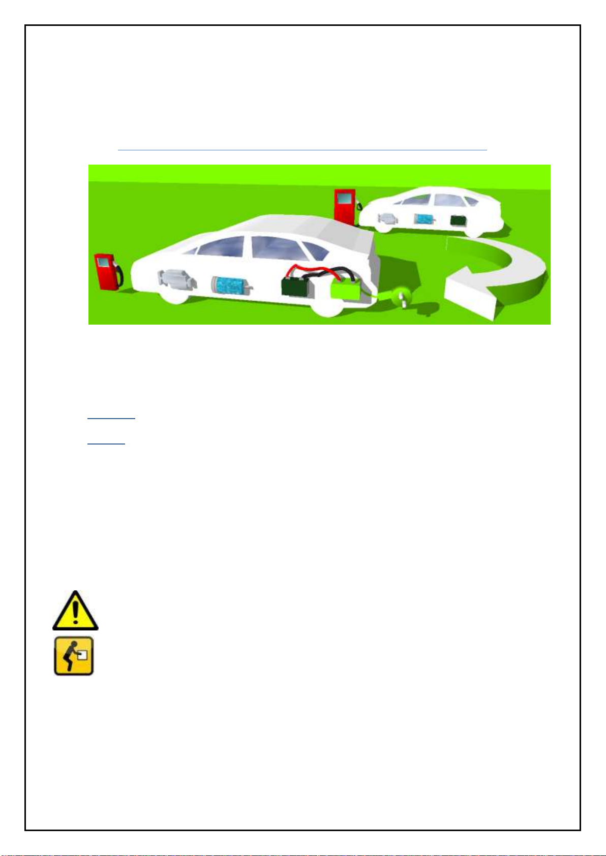
3 Overview of the conversion kit.......................................................................................................8
4 Installation......................................................................................................................................8
4.1 The kit contains the following parts .......................................................................................9
4.2 PHEV Box Wiring...................................................................................................................12
4.3 Connecting the PHEV Conversion Kit to your Prius...............................................................13
4.3.1 Required Tools for the installation ...............................................................................13
4.4 Remove Interior Trim from the rear compartment –Step 1 ................................................15
4.5 Remove Rear Floor Panels - Step 2.......................................................................................16
4.6 Remove Battery Covers - Step 3 ...........................................................................................17
4.7 Hybrid Vehicle Battery Wire connection ..............................................................................18
4.8 Install Communication cables...............................................................................................19
4.9 Install on/off switch panel. ...................................................................................................20
4.10 Switch connection to Vehicle HV ECU ..................................................................................21
4.11 Install the Bumper plug ........................................................................................................22
4.12 Mount the Kit Box ................................................................................................................23
4.13 Connect the Cables...............................................................................................................23
4.14 Install Charger's LED light .....................................................................................................23
4.15 Re-install Battery Service Plug ..............................................................................................24
4.16 Test the Kit Installation.........................................................................................................26
5 The BMS .......................................................................................................................................29
5.1 Basic Operation ....................................................................................................................29
5.1.1 Switch on the BMS........................................................................................................29
5.1.2 To switch off the BMS...................................................................................................29
5.2 The BMS Monitor .................................................................................................................29
Bottom: reset the touch screen. To reset the display update pushing data, see the
section. BMS Module Right side Buttons ....................................................................................29
5.3 The Battery System Monitor Module ...................................................................................30
5.3.1 BMS Module Left side Buttons - Balancing ...................................................................30