MDB Green Climber LV800 User manual

OPERATIONS AND MAINTENANCE MANUAL
Green Climber LV800

GREEN CLIMBER LV800

Dear Client,
Thank you for having purchased an MDB machine.
This Operations and Maintenance manual will enable you to fully appreciate the qualities of the
machine. Please read the manual entirely before starting to use the machine. The manual contains
important information, advice and warnings regarding the correct use of the machine, also allowing
you to exploit the technology of this MDB machine. The manual includes essential information
regarding the care, maintenance, operational safety, and conservation of the machine over time.
Warnings and indications that require particular attention are called up by the following symbols:
DANGER:
This symbol indicates a situation
of danger which,
if not prohibited, will result in
serious injury or death of the
persons concerned.
WARNING:
This symbol indicates a situation
of potential danger
regarding the integrity of the
machinery which, if not avoided,
may cause damage to the
machinery itself which, indirectly,
could cause serious injury or
death to the persons concerned
PLEASE NOTE:
This symbol indicates particularly
important things to enable to
work in the simplest and safest
way with the machine.
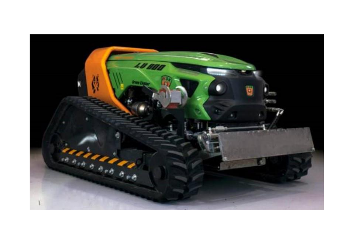
We are sure that the accurate reading of this operations and maintenance manual will allow you to
be in line with the MDB Green Climber LV800.
Pleasant reading.

TABLE OF CONTENTS
1 - DESCRIPTION OF THE MACHINE
Summary of the parts...................................................................................................................
1
Technical data .............................................................................................................................
2
General information ....................................................................................................................
4
Warranty .....................................................................................................................................
4
Manufacturer’s ID and assistance................................................................................................
6
Machine ID ..................................................................................................................................
6
Purpose of the manual, conservation and use.............................................................................
7
Knowledge of the machine...........................................................................................................
8
List of parts..................................................................................................................................
9
Demolition and disposal of the machine......................................................................................
9
Signals and alarms......................................................................................................................
10
Operating conditions ...................................................................................................................
11
Sticker legend .............................................................................................................................
13
Instructions and danger stickers..................................................................................................
14

2 - SAFETY
Rules for the safe use of the machine.........................................................................................
16
General information regarding risk analysis ...............................................................................
16
PPE for machine operations........................................................................................................
19
Reference standards for machine safety ....................................................................................
20
3 –TRANSPORT AND EMERGENCIES
Transport of the machine ............................................................................................................
22
Emergencies ...............................................................................................................................
22
4 –COMMISSIONING AND USE
Warnings .....................................................................................................................................
25
Supplies ......................................................................................................................................
25
Start-up .......................................................................................................................................
29
Stop .............................................................................................................................................
31
Equipment to use.........................................................................................................................
31
5 - CONTROL SYSTEM
Description of the control system ................................................................................................
32
Control panel................................................................................................................................
32

Remote control system................................................................................................................
36
Remote control LED indicators ...................................................................................................
37
Indications of the LEDs of the receiving unit...............................................................................
39
Battery replacement and charging ..............................................................................................
40
Use of the remote control and management of the vehicle ........................................................
42
Auxiliary controls of the equipment..............................................................................................
48
Commands on the sides of the remote control............................................................................
48
6 - MAINTENANCE AND ASSISTANCE
General indications......................................................................................................................
49
Responsibilities and tasks............................................................................................................
50
Maintenance of the engine ..........................................................................................................
54
Maintenance of the tracks ...........................................................................................................
64
Technical assistance ...................................................................................................................
65
Relay and fuse positioning...........................................................................................................
71
Quick troubleshooting guide........................................................................................................
73
List of authorised workshops.......................................................................................................
76

Attachment A: Example of EC declaration of conformity ..........................................................
80
Attachment B: Use of shredding equipment..............................................................................
81
LOG BOOK
Routine maintenance...................................................................................................................
85
Special unscheduled maintenance .............................................................................................
108

Page1
1 - DESCRIPTION OF THE MACHINE
Brief indication of the parts
1 - Tracks
2 - Oscillation
3 - Structure
4 - Motor hood;
5 - Roll-bar
6 –Cover
3
2
1
5
4
6

Page2
TECHNICAL DATA
The following images show the dimensions referring to the fully equipped machine in mm. Height
refers to the work quota.

Page3
Slight changes in measurement are possible during construction
DIMENSIONS
Machine height
1190 mm
Min. machine width
1510 mm
Max. machine width
1910 mm
Machine length
2510 mm
WEIGHTS
Empty weight of the machine with all liquids and fuel tank at
90%
Kg 1750
Motor only weight
Kg 267
Machine only weight
Kg 680
Hydraulic pumps
Kg 56
ENGINE
Engine Code
KDI2504TCR/26°
Dimensions H x W x D (mm)
719.5 x 704.3 x 3.6
Operating temperatures
-40 +50
Cycle
Eight
Water cooling
Number and position of cylinders
4 in-line
Bore (mm)
88
Run (mm)
102
Total displacement (cm3)
2482
Maximum power (CEE) (KW)
55.4
Matching capacity (rpm)
2400
Maximum torque (CEE) (Nm)
300
Matching capacity (rpm)
1500
Torque at 1000 giri/min (Nm)
226
Fuel
Diesel fuel for motor vehicles (Specification
EN590)
Power
Common rail (2000 bar) electronically
controlled

Page4
ADDITIONAL TECHNICAL DATA
Diesel tank capacity
45 l
Radiator capacity
12 l
Hydraulic oil tank capacity
32 l
Type and version of remote control
IRA Radiatori Engineering srl
RC50553712C
Type and version of remote control
IMET M880 - THOR 2 X4N
GENERAL INFORMATION
This manual contains the information and what is deemed necessary for the knowledge, good use and normal
maintenance of the ‘Green Climber LV800’ machine, also indicated as the machine, manufactured by MDB S.r.l. with
headquarters in C.da S. Onofrio n. 6/A in Lanciano (Chieti) Italy, also indicated as the ‘Manufacturing Company’ or
‘Manufacturer’. The following is a complete description of the various parts and a detailed presentation of their
operation, along with what is normally useful to know for operations in safety and for the optimum conservation of the
machine itself.
The document is an integral partof the machine and is issued by the Manufacturer, who therefore owns the copyright.
This manual is intended for personnel assigned to use the LV800 machine and contains technical standards and
drawings, which must not be reproduced (even in part), nor disclosed by any means, used for competitive purposes
nor made available to third parties by virtue of the aforementioned rights.
MDB S.r.l. therefore prohibits the total or partial reproduction of this manual and the disclosure of its contents in any
form.
WARRANTY
The warranty covers manufacturing defects. The manufacturer may not be held responsible for any damage that
occurs during transport. The machine is transported without packaging, covered with a plastic film that protects the
parts subject to oxidation in the event of contact with water or moisture. The manufacturer undertakes to perform the
fastening of the machine, assuming liability if transport is carried out with his own means.
If transport is performed by a carrier, all care will be taken to ensure that the machine is not damaged but, as already
noted above, the manufacturer assumes no liability if damage has been caused. For this reason, if transported by a
carrier, adequate insurance coverage should be requested. The customer is responsible for checking the state of the

Page5
goods on arrival and promptly notifying the carrier and the manufacturer of any damage.The machine may be packed
in a wooden crate at an additional cost, if deemed appropriate by the customer. The accessories and documents that
accompany the machine are located on board, duly protected to prevent any damage. Items not covered by the
warranty are:
- Items that are part of the machine, but that are not manufactured by MDB (such as: tracks, transmission belts,
bearings, gearboxes, etc.): these are only covered by the warranty provided by their respective manufacturers.
- Items that have deteriorated due to wear.
Exceptions that void the warranty:
- Modifications carried out on the machine without the written approval of MDB.
- Repairs carried out by unauthorised workshops.
- Use of non-original spare parts.
- Negligence during maintenance.
- Use of the machine other than that defined in this manual.
- Removing the guards installed on the machine: the guards must not be removed under any circumstances;
moreover, they must be periodically inspected, and restored to their original condition if damaged;
- Failure to comply with the machine-related safety measures mentioned in the operations manual.
The warranty period is specified in the quotation and, in any case, shall not exceed 12 months from the shipping date.
Warranty request:
A warranty request must be made in writing to MDB by the dealer, within 4 weeks from the fault, specifying: name
and address of the user; type, model, serial number, date of sale, date of the fault, number of hours of operation,
circumstances and alleged causes. For the warranty to be granted, the parts must be sent to MDB for examination
and, once confirmed, replacement of the part will be authorised.

Page6
MANUFACTURER’S ID AND ASSISTANCE
Name : MDB S.r.l.
Head office : C.da Sant’Onofrio, 6/A – LANCIANO (CH) - ITALIA
Phone : +39 0872.50221
Fax : +39 0872.50231
E-mail : info@mdbsrl.com
VAT number : 01960690699
TECHNICAL ASSISTANCE
Technical assistance is always provided by the manufacturer. For further information call: +39 0872.50221
MACHINE ID
The LV 800 is identified by CE marking, prepared in accordance with specifications provided in the 2006/42/EC
European Directive (so-called Machinery Directive), of Legislative Decree n. 17/2010 implementing the Machinery
Directive in Italy and of Italian Legislative Decree 81/08 and subsequent amendments to the Consolidated Text on
Safety in the Workplace implementing the
European directives concerning this matter.Essential data regarding markingcan be found on the ID plate positioned
in the lower part of the same machine (see the figure below: CE ID Plate).

Page7
PURPOSE OF THE MANUAL, CONSERVATION AND USE
Purpose
The purpose of the “Operations and Maintenance Manual” is to provide all those who will use the Green Climber LV800
with all the information necessary for its diligent use and maintenance in optimal conditions; particular attention has
therefore been given to ensure that this occurs in the most extensive safety conditions for operators. The equipment is
supplied to be used as specified in this manual. Operators are reminded to always be aware of safety aspects while
operating the machine, to improve its safety.
Conservation
- The following instructions must be followed closely in order to keep the manual in perfect conditions:
- Use the manual so that it is not damaged in any way;
- Do not remove, add, change or write in any part of the manual; updates may be carried out only by MDB S.r.l.
- Keep the manual in an area protected against damp, so that its life-time is not compromised;
- Hand over the manual to any other user or future owner of the machine.
Operations
Get to know the equipment before starting to use it by reading this manual carefully. Operators must be properly and fully
trained on the contents of Chapters 4 and 5 regarding machine operations and functions before using it for the first time.
The machine manufacturer may not be held responsible for damage to persons, animals, goods or the environment resulting
from the use of the equipment by operators not meeting the requirements.

Page8
INFORMATION REGARDING THE MACHINE
The following graphic illustration shows the main parts that make up the body of the MDB branded machine called ‘Green
Climber LV 800’ with numbers referring to the exploded view of the machine itself:
1. Hood kit
2. Roll-bar kit
3. Cover kit
4. 75 HP engine kit
5. Right
undercarriage kit
and track
6. Castle kit
7. Radiator kit
8. Structure kit
9. Oscillation kit
10. Hydraulic system
11. Oil tank kit
12. Left undercarriage
kit
and track
13. Stickers

Page9
LIST OF PARTS
The Green Climber LV 800 is mainly made up of:
1. S235JR steel base frame. Welded structure;
2. Tracks;
3. Hydraulic oil tank;
4. Diesel tank;
5. Hood;
6. Roll-bar;
7. Rear cover;
8. Air filter;
9. Exhaust assembly;
10. Engine;
11. Battery;
12. Remote control receiver;
13. Remote control transmitter;
14. Plate for quick coupling of equipment;
15. Control unit;
16. Headlights;
17. Flashing headlights;
18. Spare battery and battery charger for the remote control;
19. Cleanfix reversible fan;
20. Towing winch.
DEMOLITION AND DISPOSAL OF THE MACHINE
For normal disposal of machinery (after demolition), all parts must be delivered to a company specialized in the transport,
disposal and/or recovery of waste.
The LV 800 is made up of components fixed to a welded steel frame. It is moved by rubber tracks. The machine track width
is variable and can be set by means of the remote control system. The diesel engine drives the machine’s hydraulic circuit
by means of hydraulic pumps. The LV 800 is a self-propelled machine designed to be used in agriculture and forestry.

Page10
There is a quick coupling at the front, only to be used for connecting equipment designed and built by MDB. The type of
equipment that can be applied to the LV 800, (only if authorized by the manufacturer), is as follows:
- Shredder;
- Cutter
- Atomiser;
- Grass cutter;
- Snow turbo;
- Snow removal blade;
- Glass shredder;
- Forestry shredder;
- Trunk cutter
Keys for machine operations
The keys that are delivered together with the machine must be used to start up the machine (for the start-up procedure see
the relevant section of Chapter 5) to be inserted in the appropriate slot on the control panel (See photo below).
In the case of lost keys, contact the manufacturer to request copies.
SIGNALS AND ALARMS
Visual
Operators must be informed regarding visual and acoustic signals relating to the machine indicating malfunctions or failures
before using the machine. Visual signals are indicated mainly by the LEDs on the remote control displays (description in
the following Chapter 3 on the control system) and are those relating to the operations phase. There are also visual signals
on the control panel, which are mainly related to the start-up phase.

Page11
Sound
The machine is equipped with two types of acoustic signals: the horn on the machine and the buzzer on the remote control.
Both acoustic signals go off when errors occur.
On the remote control
As anticipated in the previous point, the remote control is equipped with both visual signals (LED on the display of the same)
and acoustic signals in the case of errors (buzzer). The different types of signals are specifically described in chapter 5.
OPERATING CONDITIONS
Thanks to its extremely low centre of gravity, the LV 800 machine can easily work on any type of terrain, even on steep
slopes. The recommended safe working angle is 44° with the tracks open and 40° with the tracks closed, values determined
by calculations performed in accordance with EN ISO 16231-1: 2013 which specifies the principles for risk assessment with
reference to the design and construction of self-propelled machines with operator on board used in agriculture. MDB has
tested the machine on sandy terrain up to slopes of 55°; both with the tracks open and with the tracks closed the machine
showed excellent stability in all configurations that can be reached. The technical specifications of the machine would allow
use even on slopes greater than 55°, nevertheless, the inclinations indicated above resulting from the calculation report
(40° and 44° depending on the configuration of the tracks) should not be exceeded to ensure safe use.
The remote control allows the operator to work with peace of mind even on the most uncomfortable and impractical terrain
respecting some simple indications regarding the position of the operator with respect to the machine.
Caution!
The recommended inclination for working in safety, especially on soils with conformation other than sandy, should
not be exceeded.
On steep terrain, never stand or manoeuvre the machine from a position in the area below it, as the machine
could overturn in this area. Always stand or manoeuvre the machine from the area above it.

Page12
Danger!
On steep terrain, never stand or manoeuvre the machine from a position in the area below it, as the machine
could overturn in this area. Always stand or manoeuvre the machine from the area above it.
The LV 800 was built in compliance with the applicable work safety regulations, directives and applicable European
standards. Only the equipment indicated in Attachment B of this manual can be connected to it.
Before connecting equipment other than that indicated in the above indicated Attachment, the customer must request
authorisation from MDB’s technical department, which will perform the necessary checks and reply, confirming the
possibility of connection or not. If any equipment not intended by MDB for use with the LV 800 is connected, without first
requesting authorisation and receiving a formal reply, MDB is exempted from any constructional or functional liability
regarding the machine. For reasons of safety concerning people, goods and animals, the work area where the machine
must operate must always be cleared and marked out before the start of work, and the operator must forbid entry to non
authorized persons.

Page13
STICKER LEGEND:
The following figures and table show the stickers on the machine and relative positions.
Table of contents
Other MDB Construction Equipment manuals
Popular Construction Equipment manuals by other brands

Blastrac
Blastrac BMS-150 operating instructions

STEINEL PROFESSIONAL
STEINEL PROFESSIONAL HG 2120 E Translation of the original operating instructions

Manitowoc
Manitowoc 91501 Series Operator's manual

Ammann
Ammann ATR 60 P operating instructions

Woods
Woods RB72.50 Operator's manual

Daewoo
Daewoo DAVB user manual