SKF ALEMITE 9918 User manual

Model
Low-pressure stub pump
Service guide
Date of issue April
Form number
Version

Safety . . . . . . . . . . . . . . . . . . . . . . . . . . .
Description. . . . . . . . . . . . . . . . . . . . . . .
Air motor specifications . . . . . . . . . . . . .
Pump tube specifications . . . . . . . . . . . .
Performance curves . . . . . . . . . . . . . . . .
Maintenance and repair . . . . . . . . . . . .
Overhaul . . . . . . . . . . . . . . . . . . . . . . . . .
Pump tube assembly . . . . . . . . . . . . . . .
Lubricated components . . . . . . . . . . . . .
Bench test and operation . . . . . . . . . . . .
Air line components . . . . . . . . . . . . . . . .
Troubleshooting . . . . . . . . . . . . . . . . . .
Parts list. . . . . . . . . . . . . . . . . . . . . . . . .
Tube extensions . . . . . . . . . . . . . . . . . . .
Optional accessories . . . . . . . . . . . . . . . .
Contents

Explanation of signal
words for safety
Safety
Read and carefully observe these instruc-
tions before installing/operating/trouble-
shooting assembly. Assembly must be
installed, maintained and repaired exclu-
sively by persons familiar with these
instructions.
Install assembly only after safety instruc-
tions and this guide have been read and are
completely understood.
Adequate personal protection must be
used to prevent splashing of material on skin
or in eyes.
Always disconnect power source (electric-
ity, air or hydraulic) from pump when not
being used.
This equipment generates very high
grease pressure. Extreme caution should be
used when operating this equipment as
material leaks from loose or ruptured com-
ponents can inject fluid through skin and into
body. If any fluid appears to penetrate skin,
seek attention from a doctor immediately.
Do not treat injury as a simple cut. Tell
attending doctor exactly what type of fluid
was injected.
Any other use not in accordance with
instructions will result in loss of claim for
warranty or liability.
• Do not misuse, over-pressurize, modify
parts, use incompatible chemicals, fluids,
or use worn and/or damaged parts.
• Do not exceed stated maximum working
pressure of pump or of lowest rated com-
ponent in your system.
• Always read and follow fluid manufactur-
er’s recommendations regarding fluid
compatibility, and use of protective cloth-
ing and equipment.
• Failure to comply may result in personal
injury and/or damage to equipment.
NOTE
Emphasizes useful hints and
recommendations as well as
information to prevent property damage
and ensure efficient trouble-free
operation.
CAUTION
Indicates a dangerous situation that can
lead to light personal injury if
precautionary measures are ignored.
WARNING
Indicates a dangerous situation that
could lead to death or serious injury if
precautionary measures are ignored.
DANGER
Indicates a dangerous situation that will
lead to death or serious injury if
precautionary measures are ignored.

17 in
(432 mm)
B
A
D
C
2 in NPTF (e)
1 1/2 in NPTF (i)
Fig.
Low-pressure stub pump model -A
Description
Model -A consists of an air-operated
motor and a pump tube. The air motor con-
nects directly to the double-acting recipro-
cating pump tube.
This low-pressure stub pump (: ratio) is
designed to deliver all grades of oil.
Mounting
Pump mounts directly onto original contain-
ers or bulk tanks that have a in NPTF bung
fitting. The required length downtube screws
directly into the 1/2in NPTF threads of foot
valve body.
Pump can be mounted to a wall using
wall brackets and a suction hose. Pump is
also capable of screwing directly onto
1/2in NPTF (e) or in NPTF (i) threaded
standpipes.
Table
Air motor specifications
Piston diameter in (76 mm)
Stroke 5/16 in (84 mm)
Air inlet 1/4in NPTF (i)
Max air pressure psi (10 bar)
Pump tube specifications
Material inlet in NPTF (m) / 1/2in NPTF (f)
Material outlet 1/2in NPTF
Max material pressure psi (31 bar)
Max delivery gal/min (34 l/min)
Displacement per cycle . in(172 cm3)
Item Description
AAir exhaust
B Air inlet
C Material outlet
D Material inlet

150 psi (10.3 bar)
40
32
24
16
8
1 100
800
600
400
200
1 000
900
700
500
300
100
500
400
300
200
100
25
15
30
20
10
5
100 psi (6.9 bar)
50 psi (3.4 bar)
150 psi (10.3 bar)
100 psi (6.9 bar)
50 psi (3.4 bar)
150 psi (10.3 bar)
100 psi (6.9 bar)
50 psi (3.4 bar)
150 psi (10.3 bar)
100 psi (6.9 bar)
50 psi (3.4 bar)
0 2 4 6 8 10
5 15 2510 20 30 35
Material discharge pressure
Air consumption
bar psi
SAE 10 oil at 70 °F (21 °C)
cfm lpm
gallons per minute
liters per minute
Delivery
Fig.
Delivery versus discharge pressure and air consumption
Performance curves
A pump’s ability to deliver material is based
on pressure (psi/bar) and quantity (cfm/lpm)
of air supplied to motor and amount of
material discharge [back] pressure to be
overcome within system.
This chart contains curves based on three
different air pressures. These curves relate
delivery in gallons (liters) per minute (X axis)
to air consumption in cubic feet (liters) per
minute (rightY axis) and to material dis-
charge pressure in psi/Bars (left Y axis).

Maintenance and repair
WARNING
Do not use halogenated hydrocarbon
solvents such as methylene chloride or
,,-trichloroethane in this pump. An
explosion can result within an enclosed
device capable of containing pressure
when aluminum and/or zinc plated
parts in pump come in contact with
halogenated hydrocarbon solvents.
Failure to comply may lead to death or
serious personal injury.
WARNING
Release all pressure within system prior
to performing any overhaul procedure.
• Disconnect air supply line from
pump motor.
• Into an appropriate container, operate
control valve to discharge remaining
pressure within system.
Failure to comply may lead to personal
injury.
WARNING
Do not point a control valve at any por-
tion of body or another person. Acciden-
tal discharge of pressure and/or mate-
rial can occur.
Failure to comply may lead to death or
serious personal injury.
Overhaul
NOTE
Remove cylinder with care. Damage to
quad-ring () and/or o-ring () can
occur.
Disassembly
Separate air motor from
pump tube
Clamp pump assembly in a soft-jaw vise
at body ().
Remove cover ().
. Pry and swing cover sideways
away from cylinder.
. Refer to service manual
for details.
Remove screw () from top cap.
Remove nuts () that secure body to air
motor assembly ().
Remove carriage bolts () from top cap.
. Remove keepers () from body.
Remove top cap from cylinder.
Pump tube
Tube and foot valve body
Unscrew tube () from body ().
Unscrew foot valve body () from tube.
From foot valve body remove:
–Pin ()
–Washer ()
–Spring ()
–Ball ()
–O-ring ()
Air piston
Remove screw () that secures air pis-
ton () to rod and plug assembly ().
. Remove air piston from rod and
plug assembly .
Remove washer (), quad-ring (), and
o-ring () from air piston.
Rod
Pull rod assembly from bottom of body.
Unscrew valve seat () from rod and
plug assembly.
. Remove ball ().
Remove piston () and o-ring () from
rod and plug assembly.
Remove block-v packing () from
piston.
Body
From inside body remove:
–O-ring ()
–Retaining ring ()
–Washer ()
–Seal ()
–Bearing ()
–Seal ()
With a side-to-side motion, pull cylinder
from body and air piston ().
Remove o-ring () from body.
Remove bottom cap from body.
NOTE
Refer to Fig. (page ) and Fig. IPB
(page ) for component identification
on all overhaul procedures.
WARNING
Read each step of instructions carefully.
Make sure proper understanding is
achieved before proceeding.
Failure to comply may lead to death or
serious personal injury.

A-A
5
6
7
8
9
10
11
12 14
15
16
17
18
19
20
21
22
23
24
25
26
27
28
29
30
31
32
A
A
1)
2)
) Apply thread locking compound to threads of valve seat.
) Apply thread sealant to downtube that attaches to foot valve body. Fluid may aerate.
Fig.
Pump tube assembly (without air motor) - section view

Foot valve body
Install o-ring () onto foot valve
body ().
Install ball (), spring () [small diam-
eter first], and washer () into foot
valve body.
Install pin () into foot valve.
. Make sure pin retains washer
properly and is flush with foot
valve body.
Clean and inspect
Clean all metal parts in cleaning solvent.
Solvent should be environmentally safe.
Inspect all parts for wear and/or damage.
. Replace as necessary.
Inspect air piston () for fatigue cracks.
. Replace as necessary.
Inspect rod () closely. Use a magnifying
glass to detect any score marks.
. Replace as necessary.
Closely inspect mating surfaces of all
check valve components for any imper-
fections. Ensure a smooth and clean
contact is obtained when assembled.
Example: place ball () into foot valve
body (). Fill foot valve body with sol-
vent. Make sure no leakage occurs.
Assembly
NOTE
Prior to assembly, certain components
require lubrication (→Table , page ).
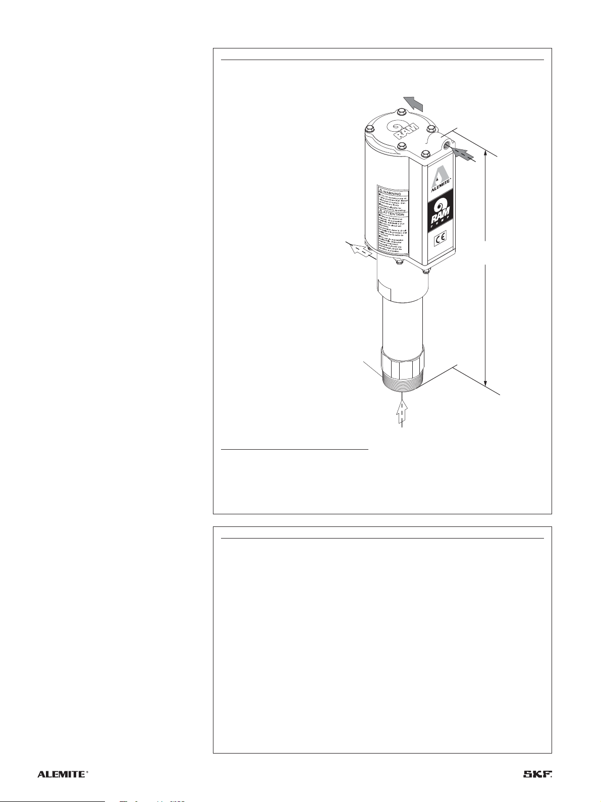
Refer to Fig. (page ) for a section
view of pump tube.
NOTE
Inspect chamber of rod for damage.
Chamber should be smooth and not
rough. If rough and not smooth, rod ()
must be replaced.
Failure to inspect may result in dam-
age to seals.
Table
Lubricated components
Item Description
Clean oil
O -ring, 3/8in ID × 1/2in OD
Quad -ring, -5/8in ID × in OD
O -ring, -3/4in ID × in OD
Seal, -5/8in ID × -7/8in OD
Seal, -5/8in ID × in OD
O -ring, -3/8in ID × -1/2in OD
Block-V packing
O -ring, -1/4in ID × -7/16 in OD
O -ring, -1/8in ID × -5/16 in OD
Coat bore of air motor assembly with PTFE grease. )
) Part number is a . ounce (21.8 g) tube of PTFE grease.
Install o-ring () onto upper groove of
body ().
Install and seat seal () [heel end first]
into bottom of body.
Install and seat bearing () [small diam-
eter first] into body.
Install and seat seal () [heel end first]
into body.
Install and seat washer () into body.
Install retaining ring () into body.
Install o-ring () into groove of body.
Rod
Install o-ring () into groove of rod and
plug assembly ().
Install block-v packing () [lips upward]
onto short end of piston ().
Install piston assembly onto rod and plug
assembly.
. Use care not to damage o-ring.
Install ball () into rod and plug
assembly.

Install rod assembly into bottom of body.
. Allow rod assembly to protrude
approximately in (5 cm) from top
of body.
Tube
Screw tube () into body.
. Use care passing block-v packing.
. Do not tighten tube at this time.
Screw foot valve body assembly into
tube.
. Tighten foot valve body assembly
securely to tube and tube to body.
Air piston
Install quad-ring () onto air piston ().
Install and seat o-ring () into bottom of
air piston.
Place air piston (observe THIS SIDE UP)
on top of rod and plug assembly.
Install screw () and washer () that
secures air piston to rod and plug
assembly.
. Tighten screw to
ft lbf (20.7 Nm).
Attach air motor to
pump tube
Clamp pump at flats of body () securely
in a soft-jaw vise.
Install bottom cap onto body.
Install o-ring () onto upper groove
of body.
NOTE
Install rod and plug assembly into body
with a twisting motion. Use care not to
damage seals.
NOTE
Install cylinder with care. Damage to
quad-ring () and/or o-ring () can
occur.
NOTE
Angle cylinder onto quad-ring ().
NOTE
Do not overtighten flange nuts ().
Component damage can occur.
Screw valve seat () with threadlocker
into rod and plug assembly.
.
Follow thread sealant manufactur-
er’s recommendations.
Install cylinder over body’s o-ring and
seat properly onto bottom cap.
Install top cap onto cylinder.
. Use care passing o-ring.
Install keeper () into groove of body.
. Make sure hole aligns with bolt ().
Install one carriage bolt through air
motor and through keeper.
Install flange nut ().
. Do not tighten flange nut at this
time.
Repeat procedural steps thru for
additional keepers and carriage bolts.
Torque each flange nut in an alternate
pattern from - in-lbf (6.8-7.9 Nm).
Install screw () into top cap.
. Tighten screw to
in-lbf (5.6 Nm)
“Snap” cover () onto cylinder.

With air pressure at zero:
Connect a product hose to pump’s mate-
rial outlet.
. Direct hose into an appropriate
collection container.
Place pump in oil.
Slowly supply air pressure to pump’s
motor.
Allow pump to cycle slowly until oil is free
of air.
NOTE
If pump assembly does not cycle, refer
to Troubleshooting (page ) for details.
NOTE
If pump assembly does not prime, refer
to Troubleshooting (page ) for details.
NOTE
If pump does not stall, refer to
Troubleshooting (page ) for details.
NOTE
If motor leaks, refer to air motor service
guide for details.
With air pressure at zero:
Attach a control valve to outlet hose of
pump.
. Make sure nozzle on control valve
is open.
Slowly supply air pressure to pump’s
motor.
Allow pump to cycle slowly until oil is
once again free of air.
Set air pressure to normal operating
pressure.
Operate control valve into a container.
Shut off control valve.
. Visually inspect pump for external
leaks.
. Pump should not cycle more than
once or twice in one hour.
Check motor for air leakage.
Bench test and
operation
Slowly supply air pressure [recom-
mended minimum of psi (1.7 bar)] to
pump’s motor.
. Pump assembly should cycle.
Installation
Additional items that should be incorporated
into air piping systems are listed in Table
(page ).
Table
Air line components
Part number Description
- Moisture separator
-B Regulator and gauge
WARNING
Do not operate pump if leakage is seen
anywhere in system.
Disconnect air to motor.
Failure to comply may lead to death or
serious personal injury.

Troubleshooting
Pump indications Possible problems Solution
Pump does not cycle. Air motor not operating properly. Inspect air motor and rebuild or replace as
necessary.
Pump tube jammed and/or contains loose components. Rebuild pump tube.
Insufficient air pressure. Increase air pressure.
Pump will not prime. Excessive cycling speed. Reduce air pressure.
Pump leaking internally. See Internal leaks.
Downtube not sufficiently tight and/or thread sealant
missing or inadequate.
Apply thread sealant ) to male pipe threads
and tighten extension.
Pump cycles rapidly. Product source empty. Replenish product
Extension not sufficiently tight and/or thread sealant
missing or inadequate.
Apply thread sealant ) to male pipe threads
and tighten extension
Pump will not stall (cycles more
than once or twice/hour).
Pump requires break-in period. Operate pump against moderate fluid pressure
for up to one hour.
Pump leaking internally. See Internal leaks.
Pump leaking externally. See External leaks.
Distribution system leaking. Correct leak.
Extension not sufficiently tight and/or thread sealant
missing or inadequate.
Apply thread sealant ) to male pipe threads
and tighten extension.
External leaks
Product leakage visible at weep
hole in body ().
Damaged seal (). Replace seal ().
Damaged rod and plug assembly (). Inspect rod and plug assembly () and replace
as necessary.
Product leakage visible at bottom
of body ().
Tu b e () not sufficiently tight. Tighten tube () into body ().
Damaged o-ring (). Separate tube () from body () and replace
o-ring ().
Air leakage at weep hole in
body ().
Damaged seal () Replace seal ()
Product leakage visible between
tube () and foot valve body ().
Foot valve body () not sufficiently tight Tighten foot valve body () into tube ().
Damaged o-ring (). Separate foot valve body () from tube ()
and replace o-ring ().
Internal leaks
Continuous slow air leak. Worn or damaged o-ring (). Replace o-ring ().
Pump does not prime or cycles
continuously, or slowly (once or
twice/hour).
Foreign material between ball () and valve seat (). Locate and eliminate source of foreign
material.
Foreign material between ball () and foot valve
body ().
Disassemble pump tube, clean, inspect, and
replace worn or damaged components.
Worn or damaged ball ().
Worn or damaged valve seat ().
Worn or damaged ball ().
Worn or damaged foot valve body ().
Worn or damaged block-v packing ().
Worn or damaged o-ring ()).
) Do not apply thread sealant to first two () threads. Contamination can occur.
) Pump may cycle once (on upstroke)

1
2
3
4
5
6
7
8
9
10
11
12
13
14
15
16
17
18
19
20
21
22
23
24
25
26
27
28
29
30
31
32
1)
2)
3)
4)
Fig. IPB
Low-pressure stub pump model -A - exploded view
) Top cap
) Cylinder
) Bottom cap
) Apply thread locking compound

Parts list
Item Description Part number Quantity
) Bolt, 1/4in - × 1/2in
Screw, cap, 1/4in - × 1/2in
Motor assembly, air
Cover (without decals)
) Screw, 3/8in - × 3/4in
Washer, 3/8in
Piston, air
) O-ring, 3/8in ID × 1/2in OD (pack of ) X-
)Quad-ring, 5/8in ID × in OD (pack of ) X-
)O-ring, 3/4in ID × in OD (pack of ) X-
Body
) Keeper
)Nut, serrated flange, 1/4in -
))Seal, 5/8in ID × 7/8in OD
)Bearing (brass)
))Seal, 5/8in ID × in OD
) Washer
)Ring, retaining
Rod and plug assembly
)O-ring, 3/8in ID × 1/2in OD
)Packing, block-V
)Piston (brass)
Ball, 7/8in diameter -
Seat, valve
)O-ring, 1/4in ID × 7/16 in OD (pack of ) X-
Tube
) Washer
)Spring, tapered
Ball, 1/4in diameter -
)O-ring, 1/8in ID × 5/16 in OD (pack of ) X-
Body, foot valve
Pin, 1/4in diameter × 1/16 in long -
Tube extensions
Container type V-cut Threaded at both ends )
gallon drum - -
gallon drum - -
/ litre drum - -
gallon bench top - -
gallon obround - -
Optional accessories
Description Part number
Low level cut-off valve
Siphon kit SWA
Wall bracket
Metal discharge hose [ ft (1.2 m)]
Part numbers left blank are not available separately.
) Included in air motor keeper repair kit ()
) Included in major repair kit (), includes tube of PTFE grease
) Seal kit (-) includes five of item number
) For use with low level cut-off valve part number

This page left intentionally blank.

This page left intentionally blank.

skf.com | alemite.com
® SKF and Alemite are registered trademarks of the SKF Group.
© SKF Group
The contents of this publication are the copyright of the publisher and may not be reproduced (even
extracts) unless prior written permission is granted. Every care has been taken to ensure the accuracy
of the information contained in this publication but no liability can be accepted for any loss or damage
whether direct, indirect or consequential arising out of the use of the information contained herein.
April · Form Version
Warranty
The instructions do not contain any information on the warranty.
This can be found in the Terms and Conditions, available at:
www.skf.com/alemite.

Модель
Столбиковый насос низкого
давления
Краткое руководство по эксплуатации
Дата издания апреля 2021
Номер формы 670790
Редакция 2

Содержание
Техника безопасности. . . . . . . . . . . . . 3
Описание. . . . . . . . . . . . . . . . . . . . . . . . 4
Пневмодвигатель . . . . . . . . . . . . . . . . .
Трубка насоса. . . . . . . . . . . . . . . . . . . . .
Кривые производительности . . . . . . . .
Обслуживание и ремонт . . . . . . . . . . . 6
Капитальный ремонт. . . . . . . . . . . . . . .
Трубка насоса в сборе . . . . . . . . . . . . . .
Смазываемые компоненты . . . . . . . . . .
Стендовые испытания
и эксплуатация. . . . . . . . . . . . . . . . . . . .
Компоненты воздухопровода. . . . . . . .
Поиска и устранения
неисправностей . . . . . . . . . . . . . . . . . . 11
Перечень деталей. . . . . . . . . . . . . . . . 13
Удлинители труб . . . . . . . . . . . . . . . . . .
Дополнительные принадлежности . . .

ПРИМЕЧАНИЕ
Обращает особое внимание на
полезные советы и рекомендации, а
также информацию для эффективной
и бесперебойной работы.
ПРЕДУПРЕЖДЕНИЕ
Указывает на опасную ситуацию, кото-
рая может привести к легким травмам
или материальному ущербу, если не
соблюдать меры предосторожности.
ВНИМАНИЕ!
Указывает на опасную ситуацию, кото-
рая может привести к жертвам или
серьезным травмам, если не соблю-
дать меры предосторожности.
ОПАСНО!
Указывает на опасную ситуацию,
которая может привести к жертвам
или серьезным травмам, если не
соблюдать меры предосторожности.
Пояснения
сигнальных слов
безопасности
Техника
безопасности
Прочтите и внимательно соблюдайте эти
инструкции по установке перед установ-
кой, эксплуатацией и устранением неис-
правностей узла. Установка, техническое
обслуживание и ремонт узла должны про-
изводиться исключительно лицами, знако-
мыми с инструкциями.
Устанавливайте узел только после про-
чтения и полного понимания инструкций
по технике безопасности и данного
руководства.
Для предотвращения попадания мате-
риала на кожу или в глаза следует пользо-
ваться подходящими средствами индиви-
дуальной защиты.
Всегда отключайте источник питания
(электрический, пневматический или
гидравлический) от неработающего
насоса.
Это оборудование создает очень высо-
кое давление смазочного материала. При
его эксплуатации следует проявлять осо-
бую осторожность, поскольку утечки мате-
риала через незакрепленные или повре-
жденные компоненты могут привести к
попаданию жидкости на кожу и в организм
человека. Если жидкость проникла под
кожу, немедленно обратитесь к врачу.
Не считайте травму простым порезом.
Сообщите лечащему врачу, какой именно
тип жидкости попал в организм.
Любое другое использование с откло-
нением от инструкций приведет к утрате
возможности гарантийных рекламаций
или ответственности фирмы-изготовителя.
• Не используйте насос не по назначению,
не создавайте избыточное давление, не
изменяйте детали, не используйте несо-
вместимые химикаты и жидкости и не
используйте изношенные и (или) повре-
жденные детали.
• Не превышайте паспортное максималь-
ное рабочее давление насоса или ком-
понента с наименьшим паспортным зна-
чением в вашей системе.
• Ознакомьтесь с рекомендациями фир-
мы-изготовителя жидкости относи-
тельно совместимости жидкостей и
использования защитной одежды и обо-
рудования и всегда следуйте им.
• Несоблюдение может привести к трав-
мам и (или) повреждению
оборудования.

17 in
(432 mm)
B
A
D
C
2 in NPTF (e)
1 1/2 in NPTF (i)
Описание
В число основных компонентов столбико-
вого насоса модели -A входят пнев-
модвигатель и насосная трубка. Пнев-
модвигатель подключается
непосредственно к трубке насоса двойного
действия возвратно-поступательного
типа.
Этот столбиковый насос низкого давле-
ния (соотношение :) предназначен для
перекачки всех сортов масла.
Монтаж
Этот насос монтируется непосредственно
на оригинальные контейнеры или
резервуары для объемных материалов,
снабженных -дюймовой пробкой с резь-
бой NPTF ). Нижняя трубка требуемой
длины ввинчивается непосредственно в
внутреннюю резьбу /дюймовой NPTF в
корпусе донного клапана.
Насос можно закрепить на стене с помо-
щью настенных кронштейнов и всасываю-
щего шланга. Насос также может навин-
чиваться непосредственно на стояки с
резьбой [ /дюймовой NPTF (e) или
дюймовой NPTF (i)].
Таблица 1
Пневмодвигатель
Диаметр поршня дюймах (76 миллиметр)
ход / дюймах (84 миллиметр)
Воздухозаборник /дюймов NPTF (i)
Максимальное давление воздуха ф/кв. дюйм (10 бар)
Трубка насоса
Вход материала дюймов NPTF (e) / /in NPTF (i)
Выход материала /дюймов NPTF
Максимальное давление материала psi (31 bar)
Объем подачи в минуту (приблизительно) gal/min (34 l/min)
Смещение за цикл . in(172 cm3)
Рис. 1
Патрубок низкого давления модель 9918-А
) Здесь и далее NPTF означает внутреннюю
нормальную коническую трубную резьбу.
Поз. Наименование
AВыпуск воздуха
B Воздухозаборник
C Выход материала
D Вход материала
Table of contents
Languages:
Other SKF Water Pump manuals

SKF
SKF MityVac MV7201 Instruction Manual

SKF
SKF Lincoln P653M User manual

SKF
SKF Lincoln P205 User manual

SKF
SKF Lincoln P205-M075 2K7-000 EEX Series User manual

SKF
SKF P623M Series User manual

SKF
SKF KFG Series User manual

SKF
SKF A Series Instruction Manual

SKF
SKF MSU Series User manual

SKF
SKF FF Series User manual

SKF
SKF K Series Instruction Manual
Popular Water Pump manuals by other brands

BUSCH
BUSCH RA 0010 C instruction manual

Crane
Crane Barnes 2SEV-L Series Installation and operation manual

Agilent Technologies
Agilent Technologies DS202 1Ph instruction manual

Kärcher
Kärcher GP 50 manual

wb compagnie
wb compagnie XC100009 manual

Johnson Pump
Johnson Pump SPX FLOW L750 LB instruction manual