Contents
Inhaltsverzeichnis
DMS measu ing amplifie GSV-4USB...................................................................................3
Desc iption.........................................................................................................................3
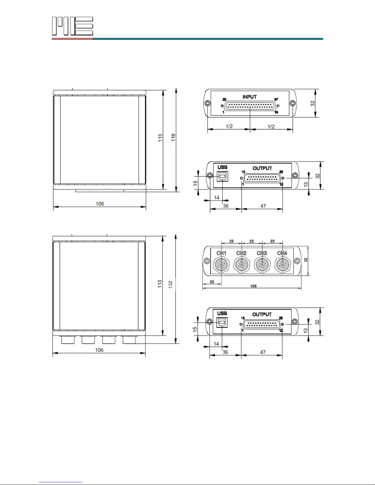
Dimensions........................................................................................................................4
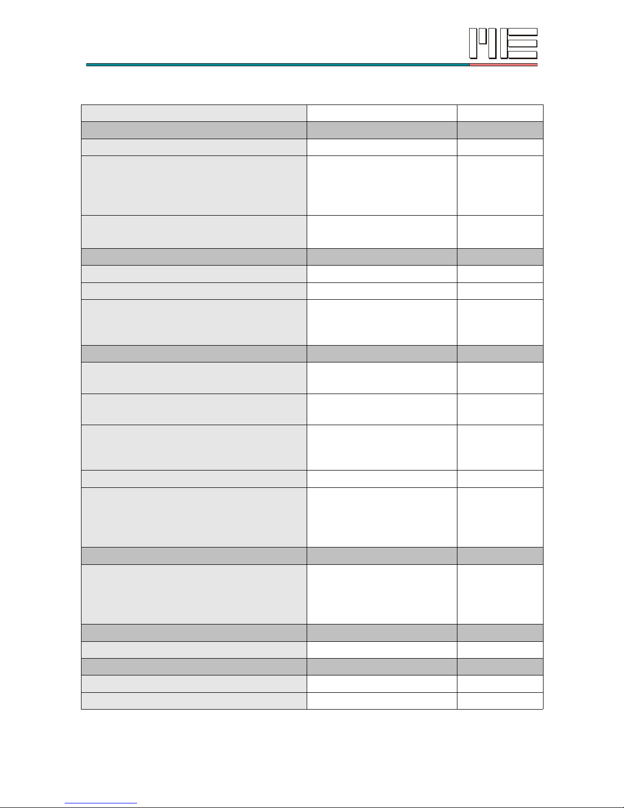
Technical data....................................................................................................................5
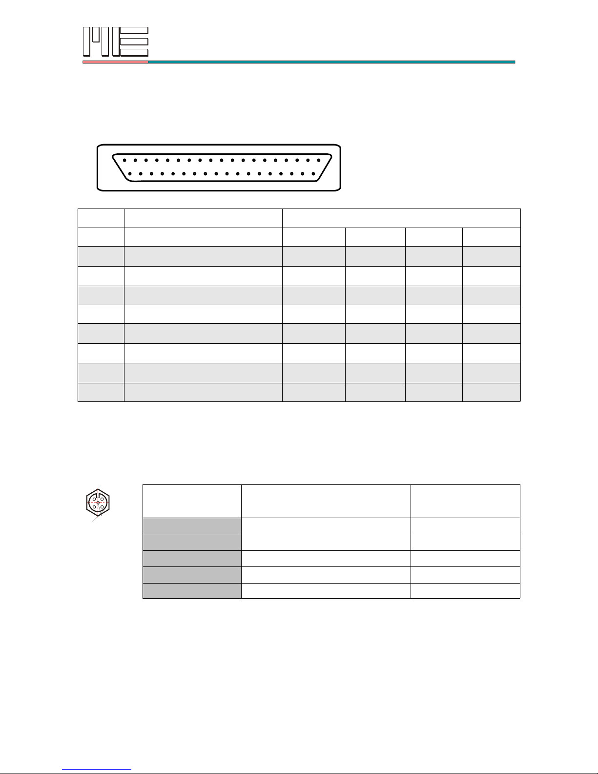
Connection assignment.....................................................................................................6
St ain Gage measu ing amplifie GSV-4BT.........................................................................17
Desc iption.......................................................................................................................17
Dimensions......................................................................................................................17
Technical data..................................................................................................................18
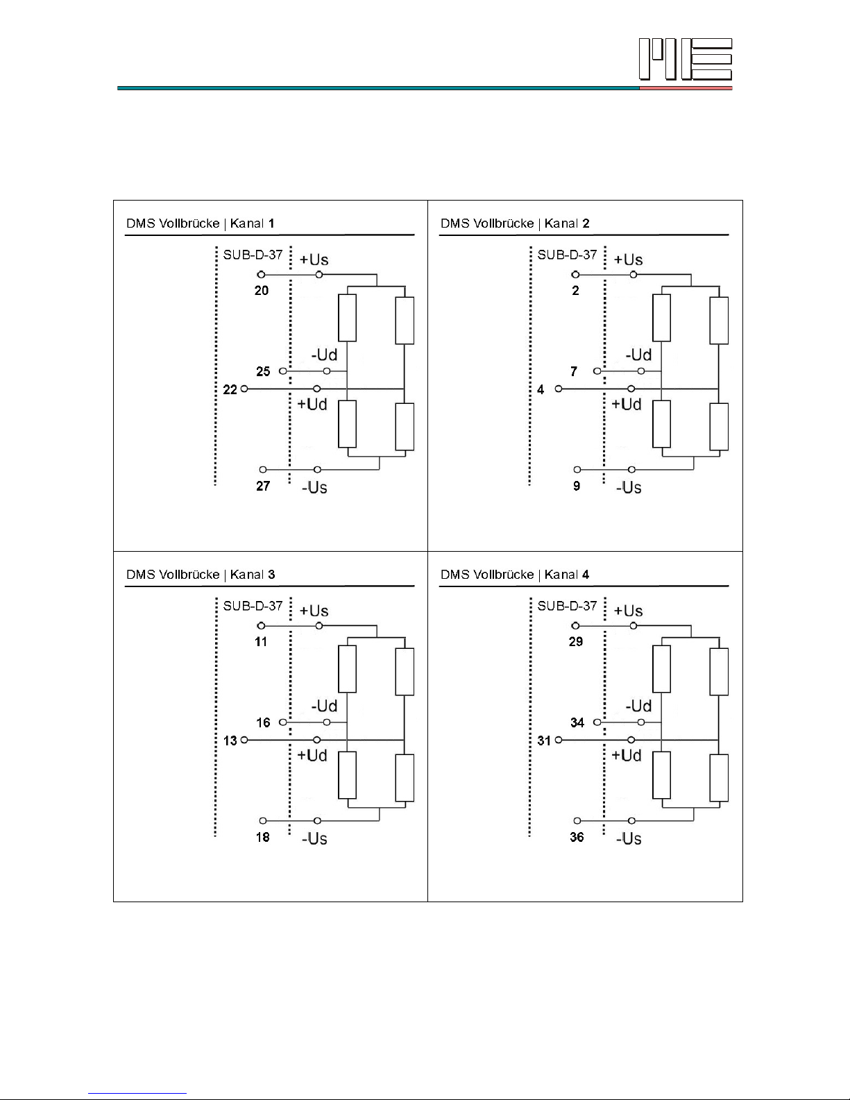
Wi ing diag am.................................................................................................................19
P og amming / configu ation................................................................................................23
Scaling of measu ed values.............................................................................................23
Measu ing ange 2.0 mV/V..............................................................................................23
Measu ing ange 10.0 mV/V............................................................................................23
Measu ing ange 0.0 to 5 V.............................................................................................24
Measu ing ange 0.0 to 10 V...........................................................................................24
Measu ing ange PT1000................................................................................................24
Measu ing ange K the mocouple cable..........................................................................24
Commands fo configu ation............................................................................................25
List of commands.............................................................................................................25
Desc iption of commands................................................................................................27
P otocol fo measu ed values..........................................................................................29
P otocol fo commands....................................................................................................29
P otocol fo esponding to commands.............................................................................30
Digital IOs........................................................................................................................31
Analogue input.................................................................................................................34
CAN bus...............................................................................................................................35
P otocol fo measu ed values..........................................................................................35
P otocol fo commands....................................................................................................35
P otocol fo esponding to commands.............................................................................35
Configu ing the CAN-ID...................................................................................................36
Data f equency and filte ..................................................................................................37
Analogue filte ..................................................................................................................37
Digital filte .......................................................................................................................37
ME-Meßsysteme GmbH, Neuendo fst . 18a, 16761 Hennigsdo f, Ge many
2
T
el +49 (0)3302 78620 60, Fax +49 (0)3302
78620 69,
[email protected], www
.me-systeme.de