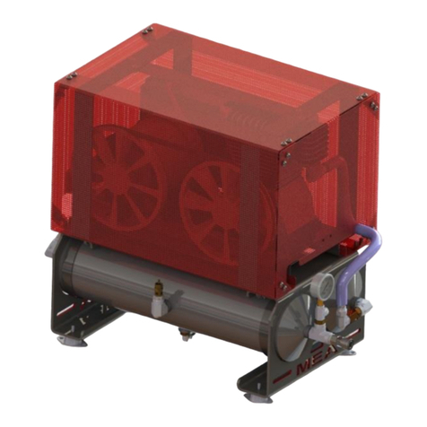
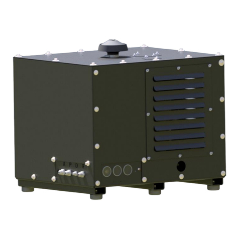
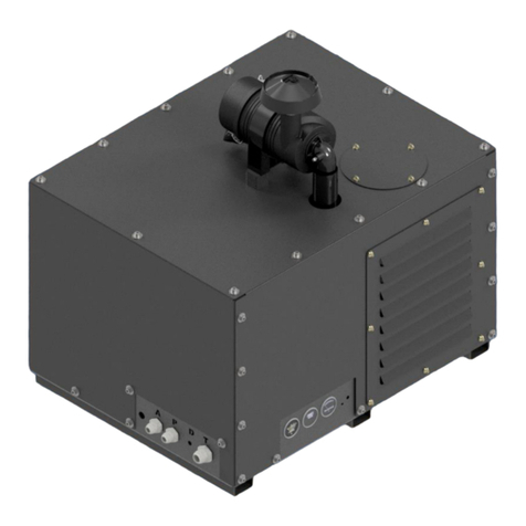
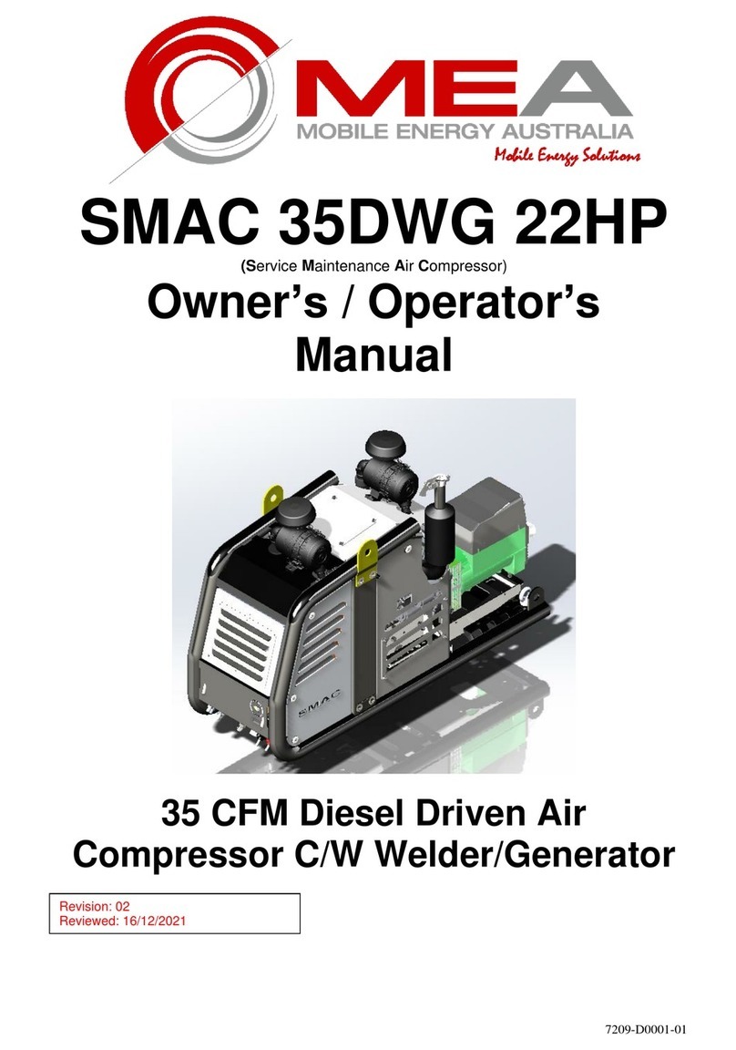
Mea SMAC35D-G 15HP Owner's manual

7201-D0001-11
SMAC 35D-G 15HP
(Service Maintenance Air Compressor)
Owner / Operator Manual
35 CFM Diesel Driven Air Compressor

Document No 7201-D0001-11

Document No 7201-D0001-11
MEA Product Warranty Registration Form
THIS FORM MUST BE COMPLETED AND
RETURNED WITHIN 30 DAYS OF INSTALLATION
OR
WARRANTY WILL BE VOID

Document No 7201-D0001-11
MEA Product Warranty Registration Form
This form must be completed and returned to MEA at the time of
Installation. Warranty will be void if this form is not received by
MEA within 30 days of installation.
MEA Dealer Information
Company Name: _____________________________________________________________
City: _______________ State: ___________________ Country : ___________________
MEA Installer Information
Company Name: ______________________________________________________________
City: _______________ State: ___________________ Country : ___________________
Installation Date: _______ / ________ / ______
Day Month Year
Owner Information
Company Name: ______________________________________________________________
Address: _____________________________________________________________________
City: _______________ State: ___________________ Country : ___________________
Postcode: _________________________ Phone #: ________________________________
Product Information
MEA Serial Number: __________________________________________________________
Model Number: _______________________________________________________________
CUT HERE

Document No 7201-D0001-11 1
Table of Contents
COMPRESSOR / COMPRESSED AIR SAFETY ......................................................................................... 2
INTRODUCTION............................................................................................................................................. 3
INTRODUCTION - COMPRESSOR SPECIFICATIONS............................................................................ 5
OPTIONAL VRD & REMOTE MOUNT VRD........................................................................................... 10
INSTALLING THE COMPRESSOR UNIT ................................................................................................ 11
SCHEDULE MAINTENANCE...................................................................................................................... 19
SPARE PARTS AND SERVICE KITS ........................................................................................................ 21
DRAWINGS & ILLUSTRATIONS.............................................................................................................. 27
Both the MEA Product Warranty Registration Form (located at the FRONT of this Manual) and the Kubota
Engine Warranty Registration Form (located at the back of this manual) are to be returned to MEA.
FAILURE TO RETURN EITHER FORM MAY RESULT IN THE PRODUCT WARRANTY BEING VOID.

Document No 7202-D0001-11 2
COMPRESSOR / COMPRESSED AIR SAFETY
MEA DISCLAIMS ANY AND ALL LIABILITIES FOR DAMAGE OR LOSS DUE TO PERSONAL INJURIES,
INCLUDING DEATH, AND/OR PROPERTY DAMAGE INCLUDING CONSEQUENTIAL DAMAGES
ARISING OUT OF ANY MEA COMPRESSOR SYSTEM NOT USED IN ACCORDANCE WITH THE
OPERATOR INSTRUCTIONS.
ALL UNITS ARE SHIPPED WITH A DETAILED OPERATOR MANUAL. THIS MANUAL CONTAINS VITAL
INFORMATION FOR THE SAFE USE AND EFFICIENT OPERATION OF THIS UNIT. CAREFULLY READ
THE OPERATORS MANUAL BEFORE STARTING THE UNIT. FAILURE TO ADHERE TO THE
INSTRUCTIONS COULD RESULT IN SERIOUS BODILY INJURY OR PROPERTY DAMAGE.
Care is required when working with an air compressor or compressed air. Compressed air is one of the many
ways energy can be stored. Releasing the stored energy in an uncontrolled manner can result in catastrophic
consequences. Death and permanent disability are all possibilities that can occur. The following are
suggested as minimum precautions to be used when operating the SMAC Air Compressor. It is important that
each work site engages in a risk analysis of that site and produces procedures in order to minimise injury to
their employees. Health and Safety Regulations today require that this is a compulsory process to be carried
out on each site. These, with site specific designed safety precautions will help to reduce accidents, personal
injury and loss of life. It is the responsibility of the employer to ensure that the work site is safe for the
employees.
SAFETY WHEN OPERATING AN AIR COMPRESSOR
Do not bypass or disable the oil temperature sensor.
Do not expose the tank or compressor to extreme heat.
Do not perform any service or repairs until the system has been completely relieved of air pressure.
Maintenance and repairs on the system should only be done by qualified personnel.
Do not operate the compressor while driving.
Do not tamper with the pressure relief valve.
Run the system at idle speed and under no load conditions for 2 to 3 minutes before turning the system off to
allow system cooling and lubrication to occur.
Follow safe work practices, wear the appropriate safety equipment when operating air-powered equipment,
particularly eye and hearing protection.
Avoid contact with rotating components, ensure all safety guards are in place.
Avoid all contact with pressurized air. If it penetrates you’re skin, it can enter your blood stream and cause
death.
To prevent compressor explosion or fire, make sure that the air entering the compressor is free of flammable
vapors.
Vaporized oil propelled by high pressure is an explosive mixture.
Do not breathe the compressor air, vaporized oil is a respiratory hazard.
Stay clear of all moving parts when the system is operating.
Follow safety procedures for tyre service operations as set by the authority.

Document No 7202-D0001-11 3
INTRODUCTION
This MEA (SMAC) Service Maintenance Air Compressor utilises a diesel engine to power the compressor. Only those
who have been trained and who have read and understand the operator and installation manual should operate and install
the MEA (SMAC). This manual contains vital information on integrating the compressor system into the vehicle system
and to ensure that it is installed and operated in a safe and efficient manner.
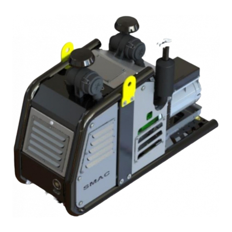
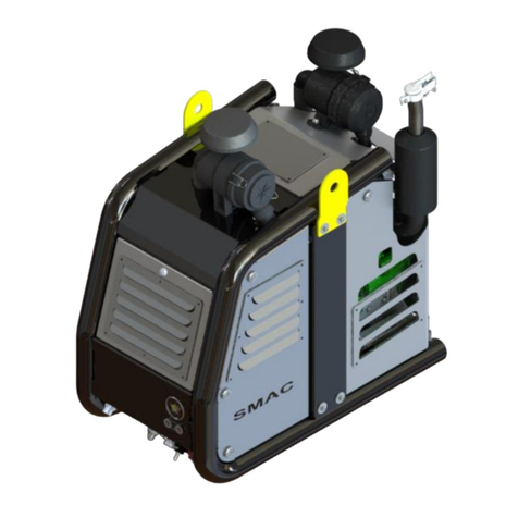
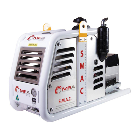
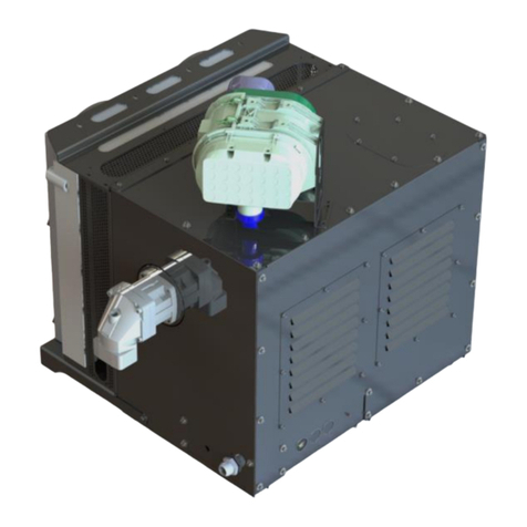
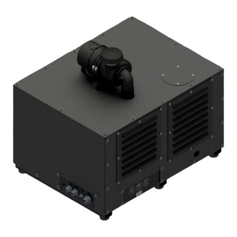
The following is a view of the SMAC compressor unit.

Document No 7202-D0001-11 4
INTRODUCTION (continued)
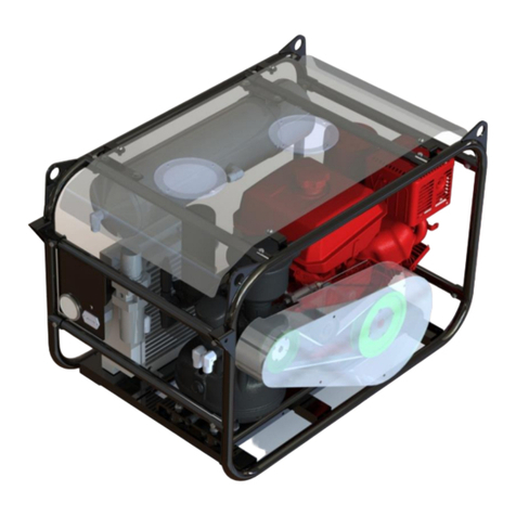
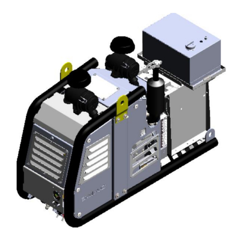
The following is a view of SMAC fitted with the generator option.
The following is a view of SMAC fitted with the generator and hydraulic pump option.
Detailed Information on the compressor and the engine are supplied separate to this Owners / Operators
Manual. The specifications on the following pages are an overview of the engine and the compressor used
on SMAC 35D-G

Document No 7202-D0001-11 5
INTRODUCTION - COMPRESSOR SPECIFICATION
Compressor Type: Oil injected rotary screw compressor
Drive System: Diesel powered via direct mechanical coupling
Control: Pneumatic
Maximum Air Delivery 35 CFM @ 150 psi
Pressure Regulation: Mechanical inlet control valve modulates flow in response to demand
Inlet Valve Regulation Pneumatic
Engine Control System: Pneumatic speed control, engine and compressor high temperature and
pressure engine shutdown system
Safety Features 200 PSI relief valve in compressor sump
Temperature safety sensor in the compressor
Rapid blow-down valve to discharge system pressure on shutdown
Lubrication: All replacement compressor oils must be approved by MEA prior to use.
Warranty will be nullified if oil has not been approved.
MEA certified and approved synthetic compressor oil
Part Number 10019 –P002
Quantity of Compressor Oil Required –4 Litres
Filters Paper-type replaceable air filters
Spin-on type compressor oil filter element
Coalescing filter element
Hydraulic Option Maximum Oil Flow 14HP 210 bar 20 lpm
Maximum Flow 24HP 210 bar 38 lpm
Alternator Option: 3 Phase Alternator optional.

Document No 7202-D0001-11 6
INTRODUCTION –15 HP DIESEL ENGINE SPECIFICATION
Engine Model: Kubota Z602
Engine Type: 2 Cylinder, water cooled, Diesel Combustion Engine
Power (continuous): 10 Kw (13.5 HP) @ 3600RPM
Electrical System: 12 Volts DC
Maximum RPM: 3160 (max bare speed) in Generator Mode
Direction of Rotation: Counter Clockwise (viewed from flywheel)
Engine Control System: Electric key start pneumatic speed control via air cylinder.
Engine Protection: Engine low oil pressure and high water temperature sensors.
Lubrication: MEA approved oil to meet strict emission control regulations, min. class “CF”
or better is required. If oil does not meet the minimum requirements, all
warranty will be nullified.
IMPORTANT:
Engine oil should be MIL-L-2104F or have properties of API classification CF
grades or higher. Change the type of engine oil according to the ambient
temperature.
Above 25°C (77°F) SAE30 or SAE10W-30 or SAE15W-40.
0°C to 25°C (32°F to 77°F) SAE20 or SAE10W-30 or SAE15W-40
Below 0°C (32°F) SAE10 or SAE10W-30 or SAE15W-40
Engine Oil quantity 2.5L
Filters: Air Filter - Paper-type replaceable (Not Possible to Clean)
Oil Filter - Spin on type (Not Possible to Clean)
Engine fuel filter –In Line Element (Not Possible to Clean)

Document No 7202-D0001-11 7
OPERATING PROCEDURE –CHECKS REQUIRED PRIOR TO STARTING EACH DAY
1. Check the oil level in the engine.
2. Check the water level in the engine.
3. Check the oil level in the compressor.
4. Check all hoses are secured and not damaged. Replace all damaged hoses before starting.
5. Check all electrical cables are secure. Secure all cables that are not tied down.
6. Check the air inlet and air filter on the engine are clear.

Document No 7202-D0001-11 8
OPERATING PROCEDURE –STARTING / STOPPING DIESEL ENGINE AND
COMPRESSOR
STARTING THE DIESEL ENGINE
1. Check the COMPRESSOR SWITCH is set to the OFF position
2. Turn the key to the left for approximately 15 seconds to prime the fuel pump and to apply power to the
glow plugs. Do not hold the key in this position for longer than 15 seconds. The system could be
damaged should you extend the time beyond the 15 seconds.
3. Turn the key to the right until the engine has started and then release the key.
4. Allow the engine to run at no load for 2-3 minutes. This will allow the engine to warm up and
lubrication system to be fully operational before the load is applied.
5. If the engine does not start, repeat the process described in 2 and 3 above. The maximum number of
attempts should be limited to perhaps 4 and after this; the operator should seek assistance from a
mechanic.
STARTING THE COMPRESSOR
1. Set the COMPRESSOR SWITCH to the ON position. This will engage the compressor load solenoid
and a green light will glow on the remote control box. The engine speed will increase until the preset
regulated pressure is reached.
2. Listen for air escaping from the pressurized air system. Ensure all air lines taps are closed in order to
reach regulated pressure.
3. If the escaping air is from a broken pipe or connection, turn the COMPRESSOR SWITCH to the OFF
position. Stop the diesel engine. Advise your maintenance department that you require their
assistance.
4. The engine will reduce its RPM when the compressor reaches the preset regulated pressure. The
compressor is now ready to be used. (It should be noted the preset regulated pressure can be
adjusted via the regulator control valve. It is recommended that your maintenance department does
this if required.)

Document No 7202-D0001-11 9
5. The compressor is ready to use.
STOPPING THE COMPRESSOR UNIT
1. Disengage the compressor by moving the compressor engage switch to the “Compressor Off”
position. Green light will turn off.
2. The compressor will shut down and bleed off pressure. The engine will come down to idle speed.
3. It is good practice to allow the engine to run under no load for 2-3 minutes.
4. Turn the engine off by turning the ignition key to the off position. If you hear a slight “hissing” noise
this is normal, the compressor is bleeding off excess pressure out of the system.
OPERATING PROCEDURE –OPERATING THE GENERATOR
OPERATING THE GENERATOR (OPTION)
1. Start engine as per previous instruction.
2. Plug the electrical load into the outlets and switch outlets on.
3. As soon as the device is switched on, the automatic current sensing device will unload the
compressor and either increase or decrease the RPM of the engine to maintain a constant 3000rpm
thus maintaining the load until the load is switched off.
4. When the load is switched off the engine will idle down in under 10 seconds.
Note:
When operating the SMAC unit, only one device can operate at one time, either the compressor or the
welder/generator. When operating the compressor the diesel engine will increase speed until it reaches
3600rpm to deliver 35cfm. When using the generator the compressor will be unloaded through the unloading
valve. The diesel engine will maintain a constant 3000rpm to ensure consistent power regulation to the
generator. These two speeds 3600rpm and 3000rpm are to ensure full engine power is used for each
operation.

Document No 7202-D0001-11 10
OPTIONAL VRD & Remote Mount VRD
The VRD relocates the welder/generator controls to a more convenient location as well as providing added
safety when welding. The VRD control box visually shows when it is safe to weld. The original controls on the
generator are blanked off and rerouted to the VRD control box.
Below pictured is the SMAC-35-WG/VRD box mounted to the side of the unit. The electrical schematic for the
VRD control box can be found in the appendix.

Document No 7202-D0001-11 11
INSTALLING THE COMPRESSOR UNIT
The compressor is a rotary screw type driven by a diesel engine. Compression occurs when inlet air (at
normal atmospheric pressure) enters a chamber where it is trapped between the rotating rotor lobes. A
lubricated pitch line provides sealing. As the lobes mesh, they reduce the volume of the air, compressing it to
the desired pressure.
The system has a two-stage air/oil separator. The first separation stage consists of baffles, which perform
mechanical separation. The second stage uses a special separation element, which delivers dry air to the
outlet. The second stage is a spin-on type coalescing filter.
Pressure regulation is achieved by adjusting the pressure regulator valve mounted in front of the compressor
(Silver adjustable valve). The system pressure is pre-set at 150 psi. To reduce the pressure, either adjust the
regulating valve or use a Filter Regulator Lubricator (FRL) to achieve the final tool pressure.
ENSURE THAT THE WATER SEPARATOR IS MOUNTED AS FAR FROM THE COMPRESSOR AS
POSSIBLE AND THAT IT HAS AT LEAST TWO METRES OF HOSING BETWEEN THE COMPRESSOR
DISCHARGE AND SEPERATOR INLET
The compressor air intake is protected by a paper-type replaceable air filter, and a spin-on type oil filter for the
oil side and a coalescing filter for final oil removal from the air
Safety features included in the compressor are:
200 PSI relief valve in separation manifold,
Blow-down valve to discharge system pressure on shutdown - will not allow compressor
restart until system pressure is below 5PSI,
Over temperature safety sensor in the compressor oil,
Over pressure mounted at the minimum pressure valve,
Do not disable or bypass the over-temperature shutdown circuits. Failure of the
shutdown system could result in equipment damage, injury or death.
A liquid-to-liquid air cooler with thermo bypass valve maintains operating temperatures in an optimal
performance range. This helps to increase system durability and reduces the temperature of the compressed
air.

Document No 7202-D0001-11 12
INSTALLING THE COMPRESSOR UNIT
The information in this section is very important for proper operation of the compressor. Read these
requirements before beginning installation. The following is a view of the compressor/diesel engine unit.

Document No 7202-D0001-11 13
INSTALLING THE COMPRESSOR UNIT
1 General Consideration Mounting the Compressor Unit
The starting point for the installation is a quick overview of the requirements. Some of these points
will be dealt with in more detail further on in this text. Things that should be considered now are as
follows;
1. The unit should be installed in a well ventilated area.
2. The unit will need to be installed level and any variation in the frame to be supported via
washers for spacers and properly secured to the vehicle by means of 5.8 grade fasteners.
3. It should be possible that the sight level glass for oil level can be checked easily.
4. It should be possible to service the unit easily without having to disconnect lines or remove
and reposition the unit.
5. The unit should be protected from excessive exposure to the elements and possible incidental
damage from other operations.
6. The unit should be installed in an area away from heat sources such as engines, exhaust
systems or other components that generate heat.
7. The unit should not be installed in a location where it will be exposed to high contamination
levels or combustible gases.
8. The engine exhaust should be routed away from the compressor unit. The engine exhaust
should be located in an area where the exhaust CANNOT be filled up with rain (an exhaust
flapper is fitted to the exhaust) however the exhaust must not face directly down to the
ground.
2 Mounting of Compressor Unit considering Ventilation
It is not possible to make absolute recommendations regarding ventilation because of the widely
differing circumstances that are possible. Duty cycle, ambient temperature and enclosure shape are
some of the important variables. Ideal ventilation will provide good airflow through the unit with no
restrictions. Broadly speaking, there are two ways in which the SMAC compressor can be mounted,
2.1 Top or Deck Mounting
This is the preferred mounting location. Placing the unit in an area where there are no restrictions on
the intake of fresh air and exhausting of hot air and exhaust gases this provides the best cooling and
ensures reliability and life for the compressor / diesel engine driven unit.

Document No 7202-D0001-11 14
INSTALLING THE COMPRESSOR UNIT
2 Mounting of Compressor Unit considering Ventilation. (Continued)
2.2 Enclosed Mounting
It is important that discussion occurs between the manufacturer and the person installing the unit
when it is to be placed in an enclosed area. Ventilation is one of the most important things to consider
when looking at the installation of a compressor/diesel engine driven unit in an enclosed area. It is
important that the air intake to the compressor and the engine exhaust are located outside of the
enclosed space. The unit generates a considerable amount of heat when running. Proper ventilation
is vital for proper operation and to avoid damage to components. Ensure there is a minimum of 10"
(250 mm) clearance between cooler grills on SMAC and any other components mounted on the
vehicle. It is strongly recommended that the installation is tested in the event that the unit is installed
in an area considered to be enclosed mounting. The following is a method suggested for testing.
1. It is best to test the installation at the hottest expected ambient temperature.
2. Setup and run the system at 120 PSI. This can be done by installing a ball valve on the air
outlet pipe and adjusting the opening of the valve so that the compressor is running
continuously at 120 PSI.
3. Record the engine, compressor and current ambient temperature for future reference.
4. Run the system at full load for at least one hour or until the temperatures stabilizes.
Temperature stabilizing means there is no rise in temperature for 15 minutes when the
compressor is running at the rated load.
5. Record the engine and compressor temperatures every 10 minutes.
6. If the system over-temps, the ventilation is not sufficient, review the installation, make
changes as needed, and repeat the test.
3 Engine Exhaust consideration when installing Diesel Engine Driven Compressor Unit
In the event that the exhaust system needs to be ducted away from the engine assembly, the
following are a minimum that should be considered
The exhaust pipe needs to be adequate for the engine.
There needs to be a flexible joint at the point where the extension is connected to the exhaust
system of the Diesel Engine Driven Compressor Unit.
Ensure the exhaust pipe has suitable clearance and does not come in contact with anything.
Ensure that if the exhaust system has a method to prevent water from entering the exhaust
system.
Ensure exhaust from the diesel engine is routed in a way to prevent recirculation back into the
unit.

Document No 7202-D0001-11 15
INSTALLING THE COMPRESSOR UNIT
4 Securing the Diesel Engine Driven Compressor Unit to the body of the vehicle.
It is important to consider maintenance needs, (in particular daily need), service requirements,
electrical connections, air connections, location of control panel before the SMAC is secured to the
body of the vehicle.
Locate a suitable mounting position for SMAC. Place the unit and check for clearances to any
other objects.
There are four weld nuts located at the four corners of the bottom formed plate which can be
used as mounting bolt locations. Holes can also be drilled through the bottom of the formed
plate if alternate locations are required.
Drill four holes in mounting surface and secure the SMAC to the truck. Use a minimum of 4 –
M12 bolts.
5 Connecting Truck Electrics to the Diesel Engine Driven Compressor Unit
Electrical connection of SMAC to the truck is very simple. The entire control system is mounted in the
SMAC.

Document No 7202-D0001-11 16
INSTALLING THE COMPRESSOR UNIT (Continued)
5 Connecting Truck Electrics to the Diesel Engine Driven Compressor Unit (continued)
1 The SMAC needs to be connected the truck battery. A minimum of 25mm cable is required for
the connection because the SMAC is started using the truck battery. SMACD units are 12 Volt
DC. In the event that a truck is 24 Volt DC (Two of 12 Volt DC batteries are supplied in the
truck), connection for the SMAC Unit will be across 1 of the batteries.
2 The start switch control box which includes the compressor load and unload switch needs to
be connected to the SMAC front panel via the Deutsch plug provided at the end of the 5
metre cable of the control box. It should be noted, this switch box can be mounted in the cab
of the vehicle if an extension harness is purchased or any location on the truck body.
6 Connection of the Diesel Engine Driven Compressor Unit to the fuel tank
It is normal to use the trucks fuel tank for all models of the SMACD. The SMACD has as standard a
fuel pump built into it. It is suggested that an additional electrical fuel pump is installed if the
compressor unit is installed 20” (500 mm) above the height of the truck diesel tank. The following is
the method for connecting up the fuel to the compressor unit.
1 Cut the feed and return lines at the tank. Install the tees into the cut pipes.
2 Install the provided check valve at the T-Piece of the feed pipe.
3 Connect the diesel feed pipe to the compressor unit from the check valve. Connect the return
line from the compressor unit to the return line tee.
7 Remote Air Intake Filter Removed For Shipping (Optional)
A label on the unit will indicate if the Air Compressor Filter has been removed for the purpose of
shipping. IT IS IMPORTANT THAT THE FILTER IS FITTED BEFORE THE COMPRESSOR IS
STARTED. The following is the instruction for fitting the filter to the compressor.
1. Remove the front access panel by pulling out the top of the panel until it is free of the rubber
mounts, lift to free from bottom rubber mounts.
2. Put the hose clamp over the air hose protruding through the top panel and push the Air Intake
Filter inlet tube into the hose.
3. Using the 2 off M8 x 30 bolts, flat washers, spring washers and nuts, bolt the Air Intake Filter
into place.
4. Tighten the hose clamp and refit the front panel.
Table of contents
Other Mea Air Compressor manuals

Mea
Mea SMAC 40D-15HP Owner's manual

Mea
Mea SMAC 35DG Owner's manual

Mea
Mea SMAC 90-H Owner's manual

Mea
Mea SMARTPACK 40H Owner's manual

Mea
Mea SMARTPACK 35 Owner's manual

Mea
Mea SMARTPACK 75-H Owner's manual

Mea
Mea SMAC 35DG Owner's manual

Mea
Mea SMAC 35DWG 22HP Owner's manual

Mea
Mea SMARTPACK 40H Owner's manual

Mea
Mea BATTCOM Owner's manual

Mea
Mea SMAC 35D-24HP User manual

Mea
Mea SMARTPACK 180-H Owner's manual

Mea
Mea SMAC 35DG/BFM Owner's manual

Mea
Mea SMARTPACK 250-H Owner's manual

Mea
Mea SMARTPACK 400-H Owner's manual

Mea
Mea VR40 Owner's manual

Mea
Mea SMARTPACK 70P Owner's manual

Mea
Mea SMARTPACK 100-H Owner's manual

Mea
Mea SMARTPACK 180-H Owner's manual