Mea SMARTPACK 35 Owner's manual
7214-D0001-01
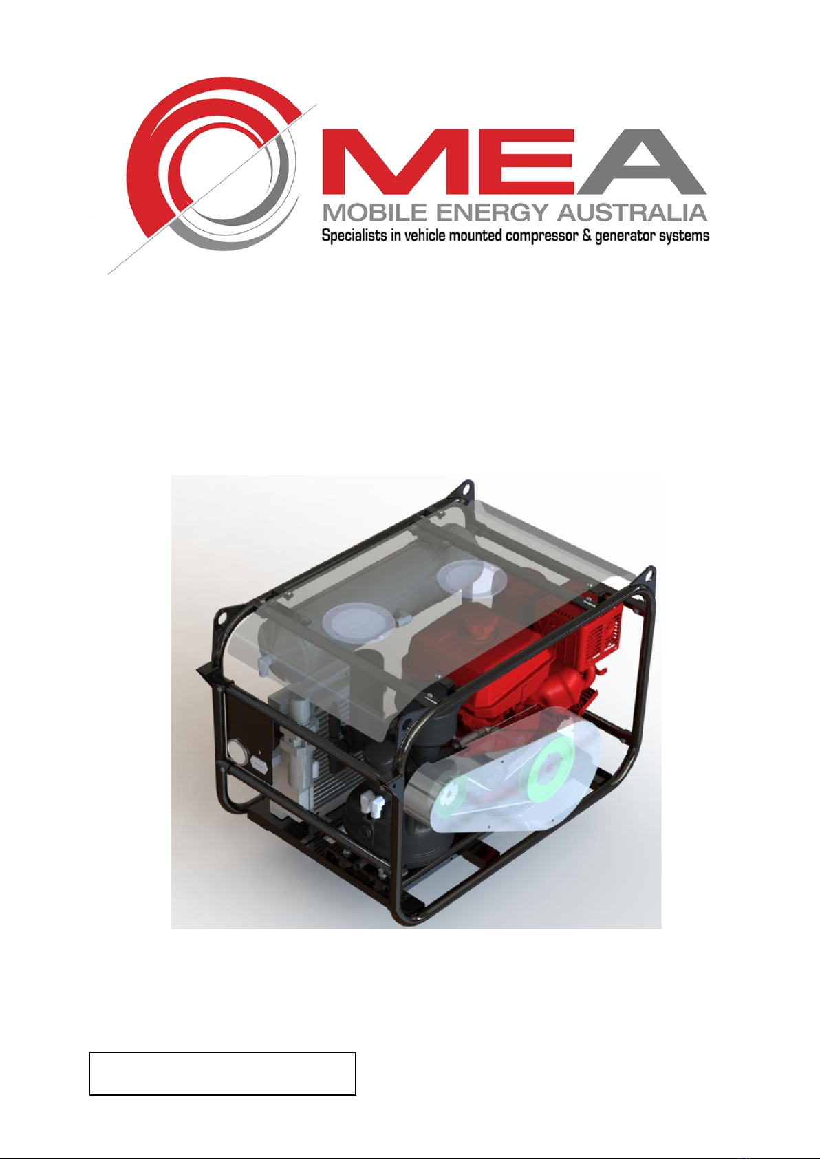
SMARTPACK 35
(SP35P SP35D)
Owners & Operators Manual
35CFM Compact Petrol or Diesel Driven
Air Compressor
Revision: 1
Revised: 03/12/2018


Document No 7214-D0001-01
Mobile Energy Australia Pty Ltd 39 Dulacca Street, Acacia Ridge QLD 4110 Australia ABN 98 674 578 946
P: +61 7 3273 6803 E: sales@mobileenergyaustralia.com.au www.mobileenergyaustralia.com.au
MEA Product Warranty Registration Form
THIS FORM MUST BE COMPLETED AND
RETURNED WITHIN 30 DAYS OF INSTALLATION
OR
WARRANTY WILL BE VOID

Document No 7214-D0001-01
Mobile Energy Australia Pty Ltd 39 Dulacca Street, Acacia Ridge QLD 4110 Australia ABN 98 674 578 946
P: +61 7 3273 6803 E: sales@mobileenergyaustralia.com.au www.mobileenergyaustralia.com.au
MEA Product Warranty Registration Form
This form must be completed and returned to MEA at the time of
Installation. Warranty will be void if this form is not received by
MEA within 30 days of installation.
MEA Dealer Information
Company Name: _____________________________________________________________
City: _______________ State: ___________________ Country : ___________________
MEA Installer Information
Company Name: ______________________________________________________________
City: _______________ State: ___________________ Country : ___________________
Installation Date: _______ / ________ / ______
Day Month Year
Owner Information
Company Name: ______________________________________________________________
Address: _____________________________________________________________________
City: _______________ State: ___________________ Country : ___________________
Postcode: _________________________ Phone #: ________________________________
Product Information
MEA Serial Number: __________________________________________________________
Model Number: _______________________________________________________________
CUT HERE

Document No 7214-D0001-01 1
Mobile Energy Australia Pty Ltd 39 Dulacca Street, Acacia Ridge QLD 4110 Australia ABN 98 674 578 946
P: +61 7 3273 6803 E: sales@mobileenergyaustralia.com.au www.mobileenergyaustralia.com.au
TABLE OF CONTENT
1. PRODUCT SAFETY .................................................................................................2
2. INTRODUCTION.......................................................................................................3
3. SPECIFICATIONS....................................................................................................4
4. OPERATING PROCEDURE.....................................................................................5
5. INSTALLATION........................................................................................................7
6. SCHEDULE MAINTENANCE.................................................................................10
7. SPARE PARTS AND SERVICE KITS ....................................................................12
8. TROUBLESHOOTING............................................................................................16
9. DRAWINGS & ILLUSTRATIONS...........................................................................19
10. WARRANTY .........................................................................................................35
MOBILE ENERGY AUSTRALIA - CONTACTS........................................................37
Both the MEA Product Warranty Registration form (located at the FRONT of this Manual)
and the Kohler Engine Warranty Registration form (located at the back of this manual) are
to be returned to MEA.
FAILURE TO RETURN EITHER FORM MAY RESULT IN THE PRODUCT WARRANTY
BEING VOID.

Document No 7214-D0001-01 2
Mobile Energy Australia Pty Ltd 39 Dulacca Street, Acacia Ridge QLD 4110 Australia ABN 98 674 578 946
P: +61 7 3273 6803 E: sales@mobileenergyaustralia.com.au www.mobileenergyaustralia.com.au
1. PRODUCT SAFETY
(COMPRESSOR / COMPRESSED AIR)
MEA DISCLAIMS ALL LIABILITIES FOR DAMAGE OR LOSS OF EQUIPMENT AND PROPERTY,
PERSONAL INJURIES (INCLUDING DEATH), AND CONSEQUENTIAL DAMAGES ARISING OUT OF
ANY MEA SYSTEM NOT USED IN ACCORDANCE WITH THE OPERATOR’S MANUAL.
ALL UNITS ARE SHIPPED WITH A DETAILED OPERATOR’S MANUAL. THIS MANUAL CONTAINS
VITAL INFORMATION FOR THE SAFE USE AND EFFICIENT OPERATION OF THE UNIT. READ THE
OPERATOR’S MANUAL BEFORE STARTING THE UNIT. FAILURE TO ADHERE TO THE
INSTRUCTIONS COULD RESULT IN SERIOUS BODILY INJURY OR PROPERTY DAMAGE.
Care is required when working with an air compressor or compressed air. Compressed air is one of the
many ways energy can be stored. Releasing the stored energy in an uncontrolled manner can result in
catastrophic consequences. Death and permanent disability are possibilities that can occur. The following
are suggested as minimum requirements to be followed when operating the MEA Smartpack system. It is
important that each work site shall perform a risk analysis and produce a procedure to eliminate or control
the hazardous conditions to minimise the risk to personnel and equipment. Health and Safety Regulations
necessitate that this is a compulsory process to be carried out on each site. These, together with site
specific safety procedures will help to minimize the risk to accidents, personnel injury, and loss of life. It is
the responsibility of the employer to ensure that the work site is safe for all employees and that the safety
procedures are followed by all employees.
SAFETY WHEN OPERATING AN AIR COMPRESSOR
•Do not bypass or disable the oil temperature and pressure sensors –unless planning on running to
failure (MEA does not recommend the practice).
•Do not expose the tank or compressor to extreme heat.
•Do not perform any service or repairs until the system has been completely relieved of air pressure.
•Maintenance and repairs on the system should only be done by qualified personnel.
•Do not operate the compressor while driving.
•Do not tamper with the pressure relief valve.
•Follow safe work practice, wear the appropriate personal protective equipment (PPE) when
operating air-powered equipment, particularly eye and hearing protection.
•Avoid contact with rotating components, ensure all safety guards are in place.
•Avoid all contact with pressurized air. If it penetrates the skin, it can enter blood stream and cause
death.
•Vaporized oil propelled by high pressure is an explosive mixture. To prevent compressor explosion
or fire, make sure that the air entering the compressor is free of flammable vapours.
•Do not breathe the compressor air, vaporized oil is a respiratory hazard.
•Stay clear of all moving parts when the system is operating.
•Follow safety procedures for tyre service operations as set by the authority.

Document No 7214-D0001-01 3
Mobile Energy Australia Pty Ltd 39 Dulacca Street, Acacia Ridge QLD 4110 Australia ABN 98 674 578 946
P: +61 7 3273 6803 E: sales@mobileenergyaustralia.com.au www.mobileenergyaustralia.com.au
2. INTRODUCTION
MEA SmartPack 35 (SP35) –Petrol or Diesel utilizes a single cylinder engine to deliver power via a drive
belt to a self-contained twin screw compressor packaged in the smallest frame possible to ensure that the
unit can be used on the back of a work utility vehicle as well as in a garage, a workshop, or a property.
This manual has important information on the system; particularly how to install, operate and maintain
properly. Refer to page seven (P.7) for information on installation as a vehicle mounted system.
Section six (6) to section seven (7) contains information on scheduled servicing and maintenance. Please
note that this is a compressor system that produces air pressure that is dangerous to humans and animals.
All service and maintenance that involves any part of the compressed air system must be carried out by a
trained professional.
Failure to do so may result in damage to equipment, total and permanent injury or in worst case, death.
MEA cannot under any circumstances, be held responsible if the compressed air system has been
tampered with by an untrained person.

Document No 7214-D0001-01 4
Mobile Energy Australia Pty Ltd 39 Dulacca Street, Acacia Ridge QLD 4110 Australia ABN 98 674 578 946
P: +61 7 3273 6803 E: sales@mobileenergyaustralia.com.au www.mobileenergyaustralia.com.au
3. SPECIFICATIONS
Compressor Type: Oil injected rotary screw compressor
Drive System: Petrol or Diesel powered via Serpentine drive belt
Control: Pneumatic
Maximum Air Delivery 35 CFM @ 150 psi
Pressure Regulation: Mechanical inlet control valve modulates flow in response to demand
Inlet Valve Regulation Pneumatic
Engine Control System: Pneumatic speed control, engine and compressor high temperature and
pressure engine shutdown system
Safety Features Relief valve in compressor sump
Temperature safety sensor in the compressor
Lubrication: All replacement compressor oils must be approved by MEA prior to use.
Warranty will be nullified if oil has not been approved.
MEA certified and approved semi synthetic compressor oil
Part Number 10019-K0005
Quantity of Compressor Oil Required ~ 3.5 Litres
Filters Paper-type replaceable air filters
Spin-on type compressor oil filter element
Coalescing filter element
Plastic fuel filter
Spin on oil filter for Diesel engines only

Document No 7214-D0001-01 5
Mobile Energy Australia Pty Ltd 39 Dulacca Street, Acacia Ridge QLD 4110 Australia ABN 98 674 578 946
P: +61 7 3273 6803 E: sales@mobileenergyaustralia.com.au www.mobileenergyaustralia.com.au
4. OPERATING PROCEDURE
CHECKS REQUIRED PRIOR TO STARTING EACH DAY
1. Check the oil level in the engine.
2. Check the oil level in the compressor.
3. Check all hoses are secured and not damaged. Replace all damaged hoses before starting.
4. Check all electrical cables are secure. Secure all cables that are not tied down.
5. Check the air inlet and air filter on the engine are clean.
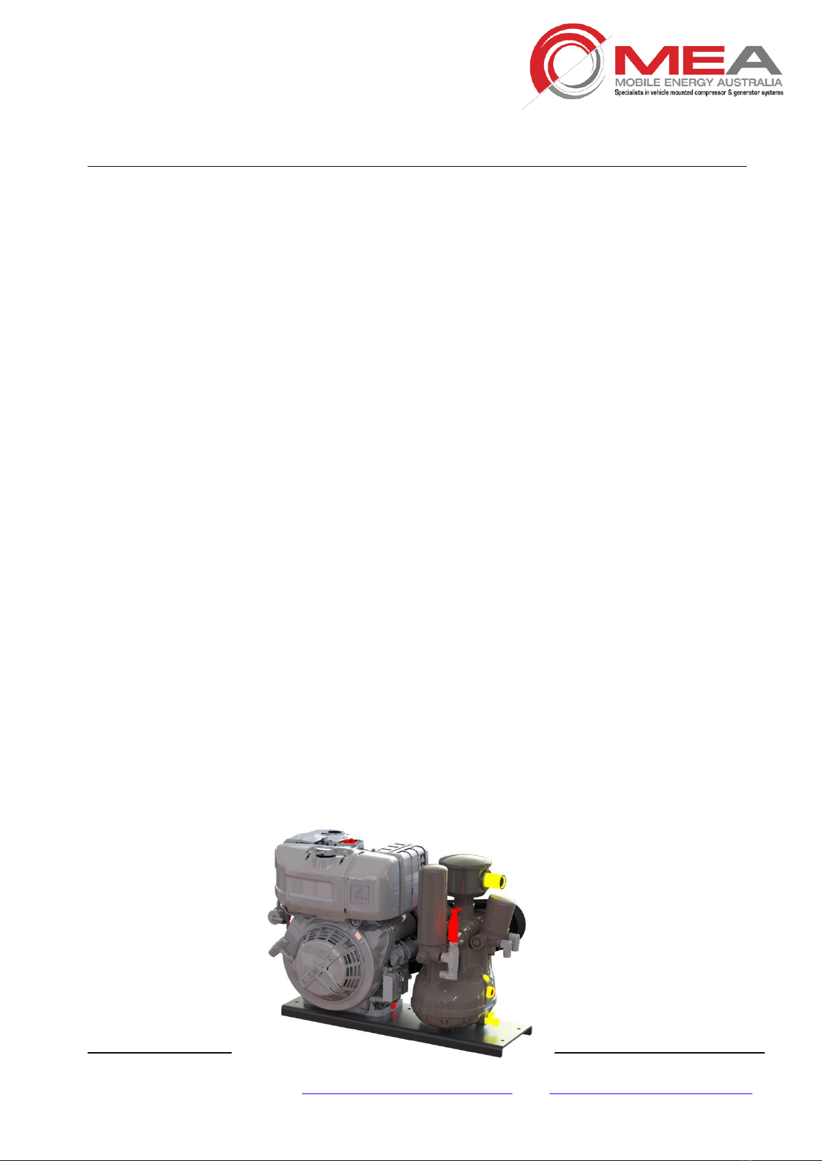
OPTIONAL OUTLET
REGULATOR
ENGINE
AIR FILTER
ENGINE
EXHAUST
HOT
9L AIR TANK
DRIVE BELT
COMPRESSOR
OIL LEVEL
TENSIONER
PULLEY
AIR OUTLET

Document No 7214-D0001-01 6
Mobile Energy Australia Pty Ltd 39 Dulacca Street, Acacia Ridge QLD 4110 Australia ABN 98 674 578 946
P: +61 7 3273 6803 E: sales@mobileenergyaustralia.com.au www.mobileenergyaustralia.com.au
OPERATING PROCEDURE - Continued
STARTING / STOPPING UNIT
STARTING THE PETROL ENGINE
1. Check the air outlet valve is closed.
2. If the engine is cold, move the choke lever to closed (under the air filter).
3. Ensure that the fuel tap is on (under the air filter).
4. Turn the key to the right until the engine starts, then release the key.
5. Move the choke lever to open, ensuring the engine is running.
6. Allow the engine to run with no load for 2-3 minutes. This will allow the engine to achieve operating
temperature. Only then is safe to load the compressor.
7. If the engine does not start, repeat the process described in 2, 3 and 4. The maximum number of
attempts should be limited to 5 and after this; the operator should seek assistance from a mechanic.
STARTING THE DIESEL ENGINE
1. Check the air outlet valve is closed.
2. Ensure that the lever on the fuel solenoid is in the downward.
3. Turn the key to the right to power the glow plugs wait till glow plug indicator light has gone out,
continue to turn the key until engine starts, then release the key.
4. Allow the engine to run with no load for 2-3 minutes. This will allow the engine to achieve operating
temperature. Only then is safe to load the compressor.
STARTING THE COMPRESSOR
1. Once the engine is running the compressor will compress air filling the tank. Ensure all valves are
closed for compressor to reach pressure.
2. Once the tank is at pressure, the engine speed drops to +/- 1200 RPM.
3. Listen for air leaks in the air system.
4. Should there be any air leaks from broken hose or connections. Stop the engine. Advise your
maintenance department that you require assistance.
STOPPING THE COMPRESSOR UNIT
1. Stop using the compressor and close the discharge valve.
2. The compressor will reach regulated pressure and the engine speed will drop to +/- 1200RPM
3. It is good practice to allow the engine to run under no load for 1 minute. (Discharge valve closed)
4. Turn the ignition key to the off position. If you hear a slight “hissing” noise this is normal, the
compressor is “blowing down” and releasing pressure out of the system.
.

Document No 7214-D0001-01 7
Mobile Energy Australia Pty Ltd 39 Dulacca Street, Acacia Ridge QLD 4110 Australia ABN 98 674 578 946
P: +61 7 3273 6803 E: sales@mobileenergyaustralia.com.au www.mobileenergyaustralia.com.au
5. INSTALLATION
The compressor is a rotary screw type driven by either a petrol or diesel engine. Compression occurs when
inlet air (at normal atmospheric pressure) enters a chamber where it is trapped between the rotating rotor
lobes. A lubricated pitch line provides sealing. As the lobes mesh, they reduce the volume of the air
(compression).
The system has a two-stage air/oil separator. The first separation stage consists of baffles, which perform
separation through gravity. The second stage uses a special separation element (a spin-on coalescing
filter), which delivers mostly dry oil free air to the outlet.
A paper-type replaceable air filter is used to filter the air coming into the compressor intake valve. A spin-on
type oil filter is used for oil filtration after the oil passes through the cooler and is returned to the
compressor.
Pressure regulation is achieved by adjusting the pressure regulator valve mounted on the compressor body
near the intake valve. The system pressure is set during final testing to 150psi if any air flow is required the
engine speed will increase to full RPM (+/-3400 RPM) and fill the tank to 150psi. If no air is used the engine
speed will drop to +/- 1200 RPM and be on standby until more air is required.
The compressor air intake is protected by a paper-type replaceable air filter, and a spin-on type oil filter for
the oil side and a coalescing filter for final oil removal from the air.
Safety features included in the compressor are:
▪150 PSI relief valve in separation manifold,
▪blow-down valve to discharge system pressure on shutdown,
▪Over temperature safety sensor in the compressor oil
▪Over pressure mounted at the minimum pressure valve,
Do not disable or bypass the over-temperature shutdown circuits. Failure of the shutdown system
could result in equipment damage, injury, or death.
An oil cooler maintains the operating temperatures in an optimal performance range. This helps to increase
system durability.
Mounting the Compressor Unit to Vehicle
Before starting the installation, have a quick overview of the requirements. Some of these points will be
dealt with in more details further on in this text. Things that should be considered before installation begins
are as follows.
1. The unit should be installed in an open area.
2. The unit needs to be properly secured to the vehicle with rubber isolators and bolted down.
3. The unit must be mounted in such a way that sight level glass for compressor oil level can
be checked easily.
4. It should be possible to service the unit easily without having to remove and reposition the
unit.
5. The unit should be protected from excessive exposure to the elements and possible
incidental damage from other operations.
6. The unit should be installed in an area away from heat sources such as engines, exhaust
systems or other components that generate heat.
7. The unit should not be installed in a location where it will be exposed to high contamination
levels or combustible gases.

Document No 7214-D0001-01 8
Mobile Energy Australia Pty Ltd 39 Dulacca Street, Acacia Ridge QLD 4110 Australia ABN 98 674 578 946
P: +61 7 3273 6803 E: sales@mobileenergyaustralia.com.au www.mobileenergyaustralia.com.au
8. The engine exhaust should be considered when installing to ensure that other components
on the vehicle do not get the heat blast.
INSTALLATION - Continued
9. If mounting the unit in an enclosed space, direct the engine exhaust outside the enclosure.
Ventilation consideration
It is not possible to make absolute recommendations regarding ventilation because of the wide variety of
circumstances that are possible. Duty cycle, ambient temperature, and enclosure shape (or footprint) are
some of the important variables. Ideal installation is where a good ventilation exists with no restrictions on
airflow. there are two ways in which the SMARTPACK system can be mounted.
Top or Deck Mounting
This is the preferred mounting location. By placing the unit in an area where there are no restrictions on the
intake of fresh air and exhausting of hot air and exhaust gases, this provides the best cooling and ensures
reliability and life for the compressor / engine driven unit.
Enclosed Mounting
It is important to seek the technical advice from manufacturer in installing the unit when it is to be placed in
an enclosed area. Ventilation is one of the most important things to consider before installation of a
compressor/ engine driven unit in an enclosed area. It is important that the air intake to the compressor and
the engine exhaust are located outside of the enclosed space.
The unit generates a considerable amount of heat when running. Proper ventilation is vital to good
operation and to avoid damage to components due to poor ventilation. Ensure there is a minimum of 10"
(250 mm) clearance between exhaust and any other components mounted on the vehicle. If this is not
possible, and was not discussed prior to purchase, please contact MEA to purchase an exhaust deflector.
If the unit is installed in an area considered to be enclosed, it is strongly recommended that the unit is
tested to certain criteria to ensure proper working. The following is a method suggested for testing.
1. It is best to test the installation at the hottest anticipated ambient temperature
2. Setup and run the system at 120 PSI. This can be done by installing a ball valve on the air
outlet pipe and adjusting the opening of the valve so that the compressor is running
continuously at 120 PSI.
3. Record the engine, compressor, and current ambient temperature for future reference.
4. Run the system at full load for at least one hour or until the temperatures stabilizes.
Temperature stabilizing means there is no rise in temperature for 15 minutes when the
compressor is running at the rated load.
5. Record the engine and compressor temperatures every 10 minutes.
6. If the system tripped on over-temps, the ventilation is not sufficient, review the installation,
make changes as needed, and repeat the test.
Completing the Installation - Before the First Start-up
Make sure that the following have been completed before operating the MEA SMARTPACK 35
Compressor Unit -
1. Check the compressor oil level; (Note that the oil is very clear, and it may be difficult to see
the level)
2. Check the engine oil level.
Document No 7214-D0001-01 9
Mobile Energy Australia Pty Ltd 39 Dulacca Street, Acacia Ridge QLD 4110 Australia ABN 98 674 578 946
P: +61 7 3273 6803 E: sales@mobileenergyaustralia.com.au www.mobileenergyaustralia.com.au
3. Check fuel level.
INSTALLATION - Continued
4. Do a final inspection to make sure that all fasteners and connections are tight.
5. Check that all hoses and wiring are secure and protected.
6. Connect the battery cables to the terminals; always connect the “Negative Terminal” first.
Check Operation –Setup & Performance Testing of Petrol Driven Compressor –
1. The compressor is dispatched from the factory with the pressures pre-set to the
customer specifications. Should the customer want to alter this setting, the instructions
on how to re-set can be found in the compressor manual.
2. Install the ball valve on the outlet of the hose from the compressor. Set the ball valve to
the closed position.
3. Refer to “Page 6” of this manual for the method to be used to start the compressor.
4. After starting, running, and charging the tank, the air pressure shall be found to be at
the pressure specified by the customer and the engine will be at the lower speed (idle
speed). Pressure settings of the unit has been adjusted by the factory to the customer
specifications. If the pressure is not at the specified pressure, contact MEA before
attempting any adjustments.
5. Listen for leaks in the air line. You should hear a hissing sound if there are any leaks.
Rectify any leak issue that you may find before starting work.
6. Keep the system running until the compressor is up to operating temperature (at which
point fan switches to “on”).
7. Using the ball valve located at the outlet of the compressor, slowly open the ball valve,
and watch the pressure drop. The pressure will drop to the point that it is 30 PSI below
the running pressure. The engine will speed up to the maximum pre-set RPM.
8. Keep the opening of the ball valve at the setting described in “step (7)” above for about
5 (five) minutes. The engine should continue to run at the maximum pre-set RPM.
9. Slowly close the ball valve and watch the pressure while closing. The engine will drop
to the lower speed when the pressure reaches running pressure.
10. It is an indication that the compressor is working perfectly if it is operating as
described. (If the performance deviates from above descriptions, please contact MEA
for technical advice)

Document No 7214-D0001-01 10
Mobile Energy Australia Pty Ltd 39 Dulacca Street, Acacia Ridge QLD 4110 Australia ABN 98 674 578 946
P: +61 7 3273 6803 E: sales@mobileenergyaustralia.com.au www.mobileenergyaustralia.com.au
6. SCHEDULE MAINTENANCE
This section is dedicated to the maintenance schedules as outlined by the engine and compressor
manufacturer under standard operating conditions. If the conditions are severe steps need to be taken for
the affected areas to be maintained at shorter intervals.
Daily inspection should happen before each start-up.
Interval
Compressor
Petrol Engine
Diesel Engine
Action to be taken
Periodically During
Operation
Observe all gauge readings. Note any change from the normal reading and determine the
cause. Have the necessary repairs made? (Note: “Normal” is the usual gauge reading
when operating at similar conditions on a day-to-day basis.)
Periodically as
required
Inspect and replace spin-
on coalescing element if
necessary.
check fuel filter periodically.
Inspect and clean oil
cooler fins.
Check for oil and/or air
leaks.
AFTER FIRST 50
HOURS OF
OPERATION
Change engine oil and oil filter
Every 10 Hours or
Daily
Check the compressor oil
level.
Check engine oil level
Check air filter/s and connecting hose and clamps
Check for oil and air system, including hoses, for leaks
Every 25 Hours or
Monthly
Drain water from than and
check Compressor oil
level
Inspect engine
After first 50 hours
of operation
Check system for oil
and/or air leaks
Check fuel hose and clamping band.
Check engine/compressor mounts fastener torque.
Change engine oil.
Check belt and pulleys for signs of wear - note that
belt normally gives off blue particles until It runs in
Replace oil carter. (In case of
low use; every 6 months)
Every 100 Hours
Check engine/compressor mounts fastener torque.
Check compressor oil
level
Change engine oil
Check system for oil
and/or air leaks
Clean air cleaner element
Check engine/compressor/generator mounts for excessive wear and fastener torque.
Every 200 Hours of
Operation or 6
months
Change engine air
intake filter if
necessary
Every 400 Hours of
operation or 9
months Engine
compressor see
Service Kit List
Change compressor oil
3L
Change Engine oil
1.1L
Change compressor oil
filter
Change engine oil
filter
Change compressor air
filter
Replace fuel filter
element if necessary
Change Spark Plug
Check valve
clearance
Check belt and pulleys for signs of wear
Check engine/compressor mounts fastener torque.
Every 500 Hours (in
case of low use
every year)
Setting and injectors
cleaning.
Setting rocker arms
clearance.

Document No 7214-D0001-01 11
Mobile Energy Australia Pty Ltd 39 Dulacca Street, Acacia Ridge QLD 4110 Australia ABN 98 674 578 946
P: +61 7 3273 6803 E: sales@mobileenergyaustralia.com.au www.mobileenergyaustralia.com.au
Every 500 Hours (in
case of low use
every year)
Change Engine oil 1.1L. In
case of low use, every year.
In using lower quality oil,
change
every 150 hours.
Change engine oil filter.
Replace fuel filter.
Change Air filter.
800 Hours / 18
months
Change compressor oil
filter
Replace engine air
filter and service as
per 400 hrs service
Change compressor
coalescing filter
Change compressor air
filter


Document No 7214-D0001-01 13
Mobile Energy Australia Pty Ltd 39 Dulacca Street, Acacia Ridge QLD 4110 Australia ABN 98 674 578 946
P: +61 7 3273 6803 E: sales@mobileenergyaustralia.com.au www.mobileenergyaustralia.com.au
7.2 OTHERS
NO
ITEM
DESCRIPTION
1
10003-P0005
ISOLATOR RUBBER
2
10004-P0166
AUTO-TENSIONER
3
10004-P0155
DRIVEN PULLEY
4
10004-P0156
DRIVER PULLEY
5
10008-P0026
REGULATOR
6
10008-P0041
OIL FILTER
7
10008-P0045
COALESCING FILTER
8
10008-P0111
AIR FILTER
9
10019-K0005
COMPRESSOR OIL 5L
(Not Shown)
10
20012-P0004
RELAY 12V (Not shown)
PETROL ENGINE
11
10004-P0165
DRIVE BELT
DIESEL ENGINE
11
10004-P0201
DRIVE BELT
PLEASE CONTACT MEA SPARE PART SALES FOR ITEMS WHICH ARE NOT COVERED HEREIN.

Document No 7214-D0001-01 14
Mobile Energy Australia Pty Ltd 39 Dulacca Street, Acacia Ridge QLD 4110 Australia ABN 98 674 578 946
P: +61 7 3273 6803 E: sales@mobileenergyaustralia.com.au www.mobileenergyaustralia.com.au
7.3 SPARE PARTS AND SERVICE KITS Cont.
SMARTPACK 35D SERVICE KITS AND PART NUMBERS
200 Hour - 7219-KB0001
Part Number
Description
Quantity
10019-K0007
OIL 5 LITRE CONTAINER DIESEL
1
10021-P0006
DECAL OIL MEA OIL
1
10008-P0126
FILTER OIL ENGINE KOHLER
1
10008-P0128
FILTER AIR ENGINE KOHLER
1
7201-P0075
DECAL NEXT SERVICE DUE
1
400 Hour - 7219-KB0002
Part Number
Description
Quantity
10019-K0007
OIL 5 LITRE CONTAINER DIESEL
1
10021-P0006
DECAL OIL MEA OIL
1
10008-P0126
FILTER OIL ENGINE KOHLER
1
10008-P0128
FILTER AIR ENGINE KOHLER
1
7201-P0075
DECAL NEXT SERVICE DUE
1
10019-K0005
OIL 5 LITRE CONTAINER COMPRESSOR
1
10001-P0076
FUEL FILTER INLINE
1
10008-P0041
FILTER OIL COMPRESSOR
1
800 Hour - 7219-KB0003
Part Number
Description
Quantity
10019-K0007
OIL 5 LITRE CONTAINER DIESEL
1
10021-P0006
DECAL OIL MEA OIL
1
10008-P0126
FILTER OIL ENGINE KOHLER
1
10008-P0128
FILTER AIR ENGINE KOHLER
1
7201-P0075
DECAL NEXT SERVICE DUE
1
10019-K0005
OIL 5 LITRE CONTAINER COMPRESSOR
1
10001-P0076
FUEL FILTER INLINE
1
10008-P0041
FILTER OIL COMPRESSOR
1
10008-P0045
FILTER COALESCING
1
10008-P0111
FILTER AIR COMPRESSOR
1

Document No 7214-D0001-01 15
Mobile Energy Australia Pty Ltd 39 Dulacca Street, Acacia Ridge QLD 4110 Australia ABN 98 674 578 946
P: +61 7 3273 6803 E: sales@mobileenergyaustralia.com.au www.mobileenergyaustralia.com.au
7.3 SPARE PARTS AND SERVICE KITS Cont.
7214 Smartpack 35P
200 Hour
Part Number
Description
Quantity
10021-P0006
DECAL OIL MEA OIL
1
10019-K0007
OIL 5 LITRE CONTAINER DIESEL
1
7201-P0075
DECAL NEXT SERVICE DUE
1
10008-P0146
FILTER AIR KOHLER CH440
1
400 Hour
Part Number
Description
Quantity
10021-P0006
DECAL OIL MEA OIL
1
10019-K0007
OIL 5 LITRE CONTAINER DIESEL
1
10019-K0005
OIL 5 LITRE CONTAINER COMPRESSOR
1
7201-P0075
DECAL NEXT SERVICE DUE
1
10008-P0041
FILTER OIL COMPRESSOR
1
10008-P0146
FILTER AIR KOHLER CH440
1
800 Hour
Part Number
Description
Quantity
10021-P0006
DECAL OIL MEA OIL
1
10019-K0007
OIL 5 LITRE CONTAINER DIESEL
1
10019-K0005
OIL 5 LITRE CONTAINER COMPRESSOR
1
7201-P0075
DECAL NEXT SERVICE DUE
1
10008-P0041
FILTER OIL COMPRESSOR
1
10008-P0045
FILTER COALESCING
1
10008-P0111
FILTER AIR COMPRESSOR
1
10008-P0146
FILTER AIR KOHLER CH440
1
Document No 7214-D0001-01 16
Mobile Energy Australia Pty Ltd 39 Dulacca Street, Acacia Ridge QLD 4110 Australia ABN 98 674 578 946
P: +61 7 3273 6803 E: sales@mobileenergyaustralia.com.au www.mobileenergyaustralia.com.au
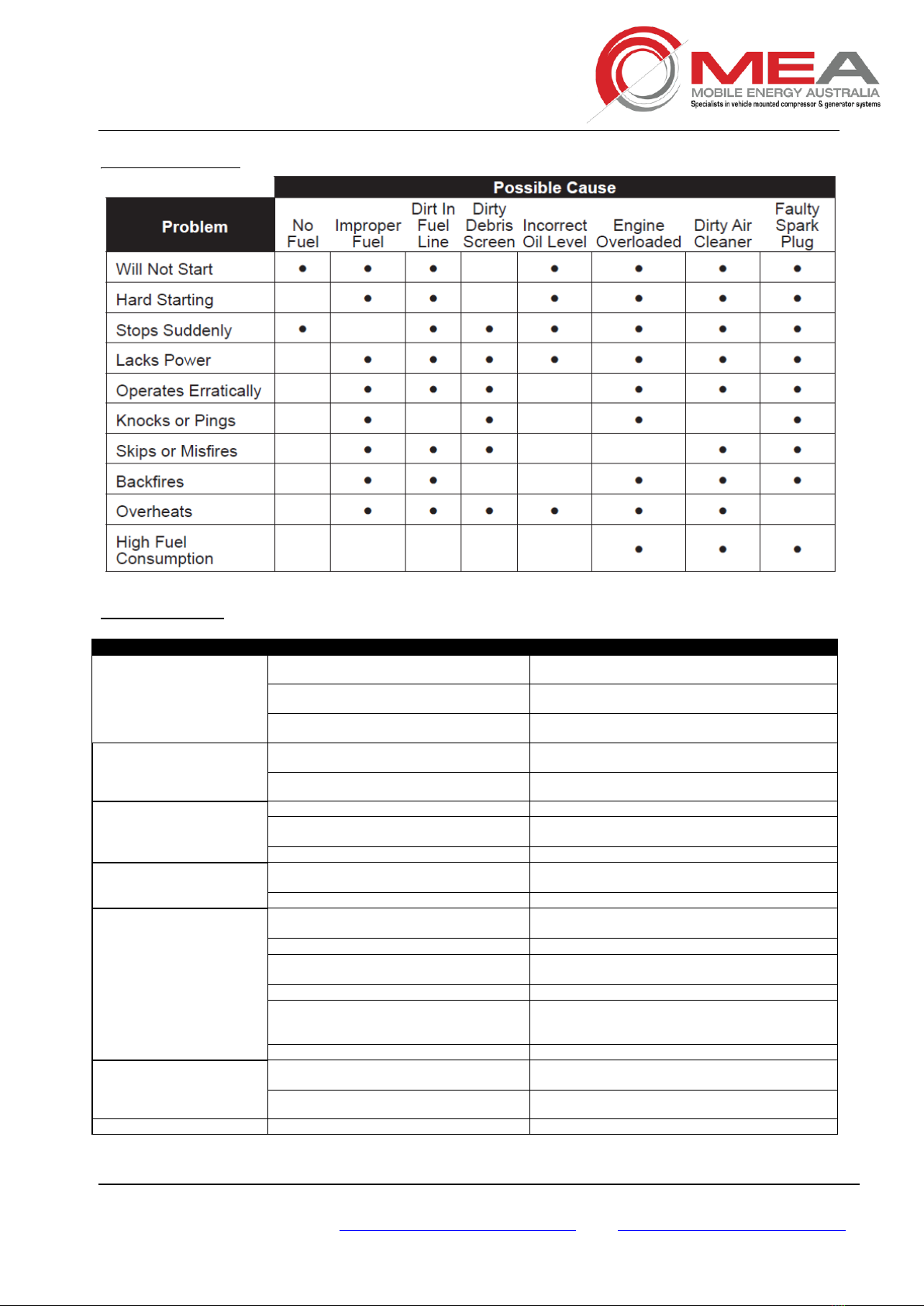
8. TROUBLESHOOTING
PETROL ENGINE
COMPRESSOR
SYMPTOMS
PROBABLE CAUSE
CORRECTIVE ACTION
The compressor does not
load.
1-The intake valve remains closed.
1-Check the valve. If necessary, replace the
damaged parts with the spare parts kit.
2-The solenoid valve does not work
accurately
2-Check the solenoid valve. If necessary, replace it.
3-Losses on the pressure line.
3-Check pipes and cables. If necessary, replace
them.
During idling phase, the
compressor does not
discharge pressure from
separator tank
1-The solenoid valve does not work
accurately.
1-Check the solenoid valve. If necessary, replace it.
2-The calibrated nozzle is clogged.
2-Remove the calibrated nozzle. Clean or replace it.
Compressor capacity or
pressure lower than usual
standard.
1-The air filter is clogged.
1-Remove the air filter. Clean or replace it.
2-The intake valve does not open.
2-Check the valve. If necessary, replace the
damaged parts with the spare parts kit.
3-Air loss from safety valve.
3-Replace the valve.
Compressor keeps on
loading over working
pressure: safety valve opens
1-The solenoid valve does not work
accurately.
1-Check the solenoid valve. If necessary, replace it.
2-Clogged separator filter.
2-Replace the separator filter.
Compressor overheating.
1-Insufficient cooling.
1-Check the cooling system. Check coolant level on
tank.
2-Dirty oil
2-Replace it with new oil.
3-Oil level is too low.
3-Check coolant level on tank and if necessary, add
oil.
4-Clogged-up cooler or pipe connection
4-Clean cooler and pipes.
5-The thermostatic valve does not work
correctly.
5-Check the thermostatic valve. If necessary,
replace the damaged parts with spare parts kit (
Contact MEA for parts required)
6-Clogged oil filter
6-Replace the oil filter
During unloading phase,
pressure increases up to
safety
valve opening
1-The intake valve remains open.
1-Check the valve. If necessary, replace the
damaged parts with spare parts kit.
2-The calibrated nozzle is clogged.
2-Remove the calibrated nozzle. Clean or replace it.
Oil leakage from intake
1-The intake valve does not work properly
1-Check the valve. If necessary, replace the
This manual suits for next models
2
Table of contents
Other Mea Air Compressor manuals

Mea
Mea SMAC 40D-15HP Owner's manual

Mea
Mea SMARTPACK 100-H Owner's manual

Mea
Mea VR40 Owner's manual

Mea
Mea SMAC 35DG Owner's manual

Mea
Mea SMARTPACK 250-H Owner's manual

Mea
Mea SMAC 35DG/BFM Owner's manual

Mea
Mea BATTCOM Owner's manual

Mea
Mea SMARTPACK 70P Owner's manual

Mea
Mea SMAC 35D-24HP User manual

Mea
Mea SMAC 90-H Owner's manual

Mea
Mea SMAC35D-G 15HP Owner's manual

Mea
Mea SMARTPACK 75-H Owner's manual

Mea
Mea SMAC 35DWG 22HP Owner's manual

Mea
Mea SMARTPACK 400-H Owner's manual

Mea
Mea SMARTPACK 180-H Owner's manual

Mea
Mea SMARTPACK 180-H Owner's manual

Mea
Mea SMARTPACK 40H Owner's manual

Mea
Mea SMAC 35DG Owner's manual

Mea
Mea SMARTPACK 40H Owner's manual


