Measurement Systems International MSI9750A User manual


Page 2 MSI-9750A RF Remote Indicator • User Guide
9750A HANDHELD RF REMOTE INDICATOR for CELLSCALE
®
This Page Intentionally Left Blank

MSI CellScale® System • 9750A User Guide Page 3
MEASUREMENT SYSTEMS INTERNATIONAL
Firmware Version 2-XX
TABLE OF CONTENTS
SECTION 1– INTRODUCTION & ORIENTATION ............ 4
9750A Keyboard .............................................. 4
Key Descriptions ............................................. 5
9750A Display Symbols .................................. 6
General Information ......................................... 7
Manual & 9750A Conventions ........................ 7
Features ............................................................ 8
9750A Block Diagram ..................................... 8
The CellScale Family ...................................... 9
Unit Installation ............................................. 10
Battery Installation ......................................... 10
Charger Adapter ............................................. 10
Charging the Battery ...................................... 10
SECTION 2 – RF SCALE COMMUNICATIONS ............ 11
FCC Statement ............................................... 11
RF Network Description ................................ 11
Antennas ........................................................ 11
RF Network Setup ......................................... 12
Configuring for multiple networks ................ 12
Troubleshooting RF Connection Problems .... 14
RF Site Testing ............................................... 15
RF Network Auto Scan .................................. 15
SECTION 3 – SCALE OPERATION .............................. 16
Power ............................................................. 16
Multiple Scale Channels ................................ 16
Selecting the Active Channel ......................... 16
Select the Display Channel ............................ 17
Multi-Channel Systems ................................. 17
Multi-Channel Page Display .......................... 18
Zero ................................................................ 18
Tare ................................................................ 19
Clear Tare ....................................................... 19
Setup Tare Mode ............................................ 20
Net/Gross ....................................................... 20
Units ............................................................... 21
Peak Hold ....................................................... 21
Send/Print ...................................................... 21
Display Test ................................................... 21
SECTION 4 – FUNCTION KEYS ................................. 22
Define Function Keys .................................... 22
Function Key Descriptions ............................ 23
View Function Keys ...................................... 24
Custom Function Key Labels ........................ 25
SECTION 5 – ID CODES .......................................... 26
ID Code Organization .................................... 26
Setup ID Codes Menu .................................... 27
Using ID Codes .............................................. 28
Default ID Code ............................................. 28
ID Code String 1 & 2 ..................................... 29
SECTION 6 – TOTAL / STATISTICS ............................ 30
Total ............................................................... 30
Auto Total ...................................................... 30
Setup Total Menu .......................................... 31
Turning Auto Total On & Off ........................ 32
View Total & Statistics .................................. 32
Clearing Totals ............................................... 33
Clear All Totals (All ID Codes at once) ......... 33
Statistics ......................................................... 33
View Statistics and Grand Statistics .............. 34
SECTION 7 – 9750A METER SETUP ........................ 35
System Setup Menu ....................................... 35
Set Time & Date ............................................ 35
Password Locks ............................................. 36
Keyboard Lock .............................................. 37
Display Setup ................................................. 37
Single Channel Preset Displays ..................... 38
Multi-Channel Preset Displays ...................... 39
Display Setup Menu ...................................... 39
Using Display Setup ...................................... 41
Custom Display Setup ................................... 42
Custom Display Setup Procedure .................. 45
Single Channel Custom Display Menu .......... 46
Multi-Channel Custom Display Menu ........... 47
SECTION 8 – SET POINTS ........................................ 48
Set Point Setup Menu .................................... 49
To Activate/Inactivate all Set Points .............. 50
Program Set Point Menu ................................ 51
9750A Set Point Response Menu .................. 51
Set Pont Formula Menu ................................. 52
SECTION 9 – COMMUNICATION PORT ...................... 53
Cabling ........................................................... 53
Trigger Print ................................................... 53
Comm Port Setup Menu ................................ 54
Enter / Edit Strings ......................................... 55
General Text Entry ......................................... 56
Printer Output Formatting .............................. 58
End of Line / Start of Line Strings ................. 59
Text / Control Character Entry ...................... 59
Serial Output “@” Commands ...................... 60
SECTION 10 – DATA LOGGING ................................ 68
Data Logging Setup ....................................... 68
Data Logging Control Menu .......................... 68
Auto Print to Memory .................................... 69
SECTION 11 – TEXT MESSAGING ............................. 70
Host Message Design .................................... 70
9750A to Host Message ................................. 71
SECTION 12 – BAR CODE FUNCTIONS ..................... 72
Bar Code Setup Menu .................................... 72
SECTION 13 – CHANNEL SETUP AND CELLSCALE CALI-
BRATION .......................................................... 74
Channel Setup Menu ...................................... 74
Calibrate General Information ....................... 75
Enable Calibration ......................................... 75
Calibration Procedure .................................... 75
Enable/Disable AZM ..................................... 76
Motion Band .................................................. 77
Center of Zero Indicator ................................ 78
Motion Compensation Option ....................... 78
Reset All ......................................................... 79
Installing Firmware Updates .......................... 79
APPENDIX A – MENU MAPS .................................... 82
APPENDIX B – ASCII CHART ................................. 95
APPENDIX C – SPECIFICATIONS & FEATURES .......... 96
THE MSI LIMITED WARRANTY .............................. 97
Page 4 MSI-9750A RF Remote Indicator • User Guide
9750A HANDHELD RF REMOTE INDICATOR for CELLSCALE
®
SECTION 1 – INTRODUCTION & ORIENTATION
INTRODUCTION
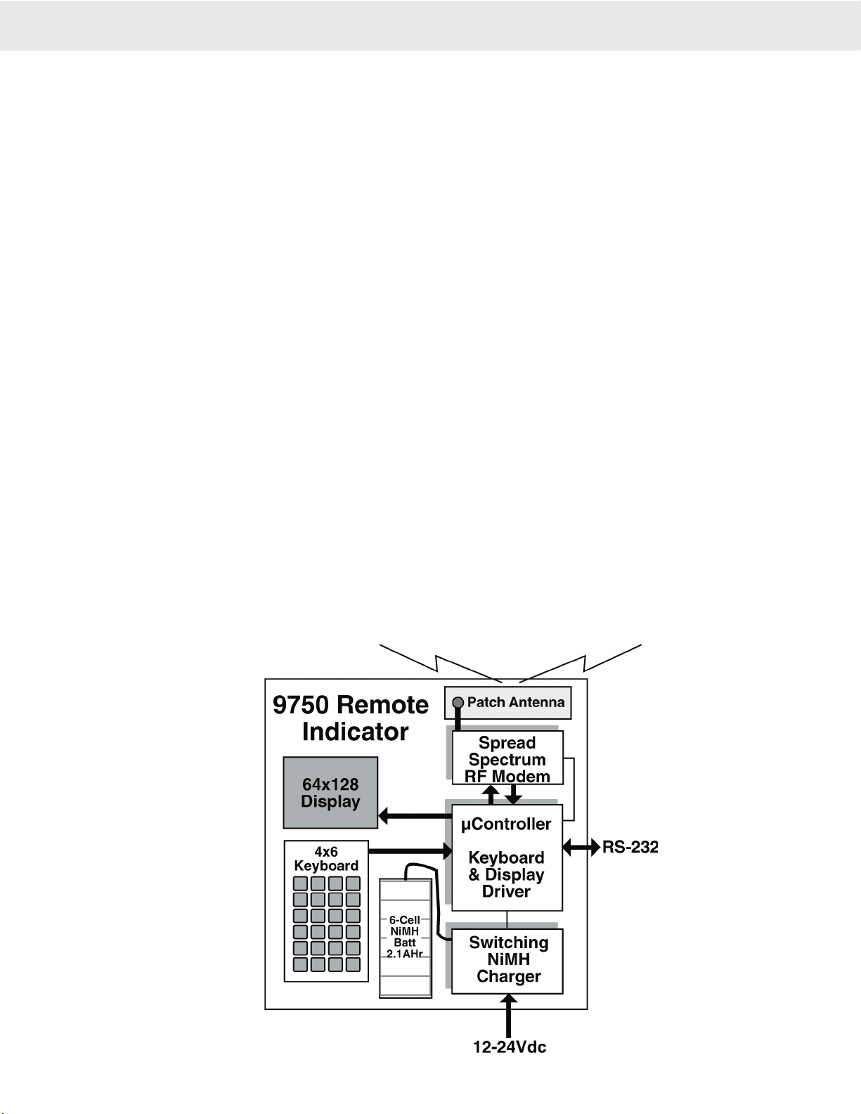
The Measurement Systems International MSI-9750A RF Remote Indicator is an accessory component of MSI's
CellScale® System. Combined with 1 or more CellScales, the 9750A provides complete control over all scale and
data functions. The 9750A serves as a remote terminal for any CellScale and has no internal measurement capa-
bility. One 9750A can read the output of many CellScales, and 1 CellScale can also provide data to many 9750's.
The backlit, alphanumeric graphic display provides precise, unambiguous indication of operating modes such as
Net, Gross, or Total. The 9750A can calibrate a CellScale remotely and provides a user interface to the advanced
features of the CellScale. The CellScale system is digitally calibrated from either the 3750CS Indicator, a 9750A
Indicator, or with a terminal program hooked directly to the CellScale model 9000. The 9750A combined with a
CellScale is designed to meet or exceed the requirements of all regulatory agencies.
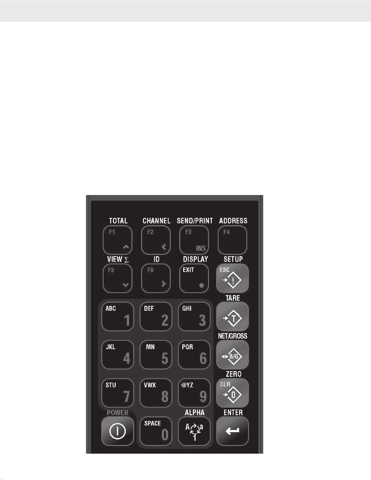
9750A KEYBOARD
MSI CellScale® System • 9750A User Guide Page 5
MEASUREMENT SYSTEMS INTERNATIONAL
Firmware Version 2-XX
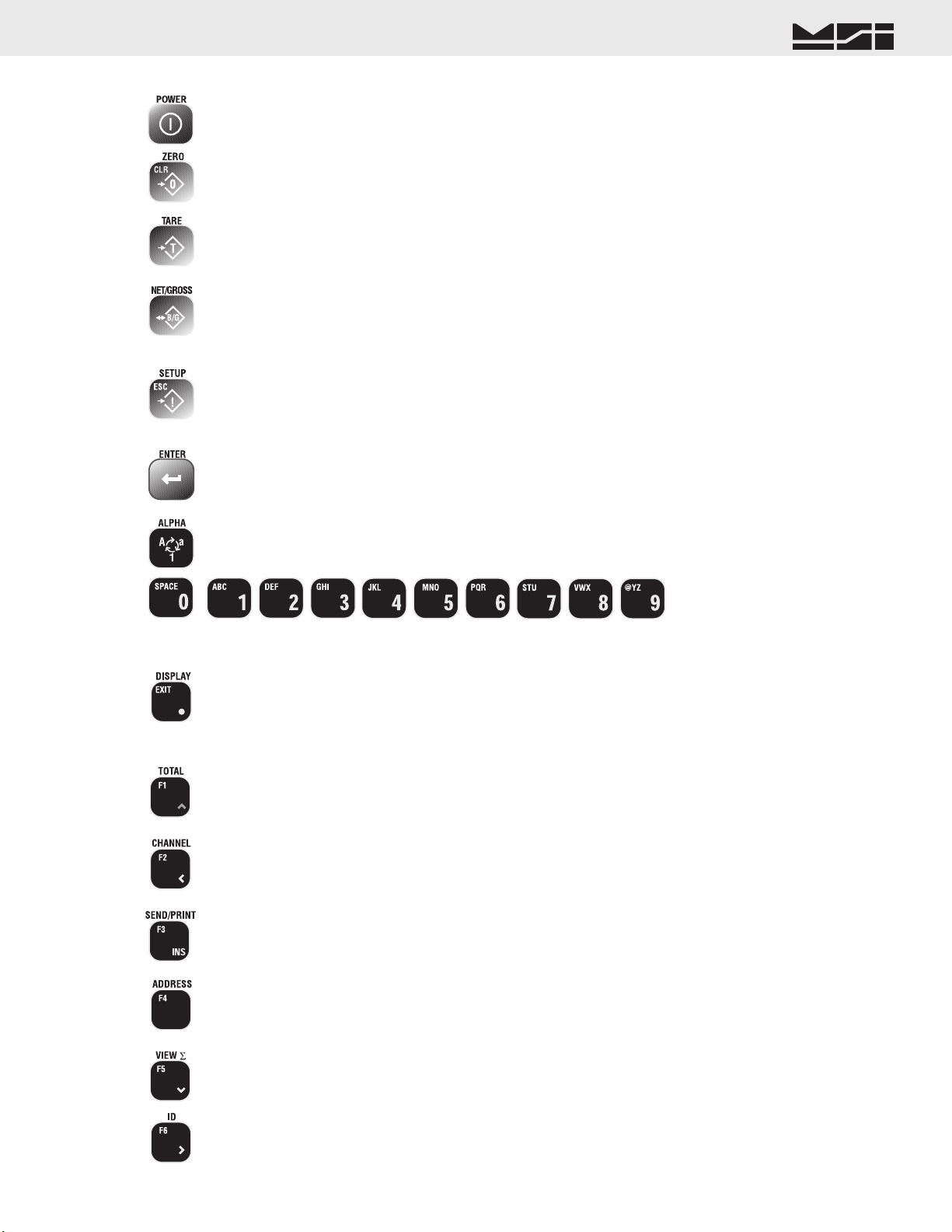
KEY DESCRIPTIONS
The POWER key turns the 9750A On and Off. The POWER key must be held for 1 second to ensure startup.
The ZERO key is used to zero out residual weight on the scale. When entering numbers or strings the ZERO key is used
to Clear (delete) characters.
The TARE key is used to zero out the weight of containers, trucks, or carriers and to place the scale in the Net weight
mode.
The NET/GROSS key allows the operator to alternate the weight display from Net (Tared) weight to Gross weight. In
some Legal-for-trade jurisdictions, the Gross weight display is limited to 3 seconds.
The SETUP key allows entry into the setup submenus. Use this to find menus for setting the Date and Time, setting up
the function keys, controlling the display mode and backlight, password locks, calibration, etc.. The key is also used for
ESCape. Use ESC to return to the previous menu, or display mode.
The ENTER key finalizes the entry of numeric or alphanumeric text entries. It also provides an alternate way to maneu-
ver through menus combined with the cursor keys. Pressing ENTER before certain keys takes you directly into various
modes. Pressing ENTER before a Function key enacts the alternate Function key mode.
The ALPHA key is used during text entries to select upper case, lower case or numbers. Sometimes used for negative.
The numeric keypad provides all numerals and letters for data entry. Submenus provide punctuation and control charac-
ters.
The DISPLAY key is used to alternate between single channel displays and multiple channel displays. While in the
multiple channel display, highlight the desired channel using the numeric keys, then press DISPLAY to bring up the
large display. This selected channel is the “Active” channel to which all subsequent actions will be applied. Provides
the decimal point or period in numeric and text entries. Functions as EXIT in menus returning directly to weight display
without having to back through all previous menus.
F1 defaults to TOTAL. Pressing this key will cause the current weighment to be added to the total register. In Auto-Total
modes, the TOTAL key turns Auto-total off and on. Up Cursor in menus.
F2 defaults to CHANNEL. When the CellScale has more than 1 channel defined in its Scan List, the CHANNEL key
will select the next active channel in the list. Precede the CHANNEL key with a numeric entry (1-32) to switch directly
to a channel scan list position. Press SETUP CHANNEL for a shortcut to the “Channel Setup Menu”. Left Cursor in
menus.
F3 defaults to SEND/PRINT. The action of this key is dictated by the Function key menu, but is usually used to send
data to the CellScale or one of its hosts. Used for Insert in text and number entry screens.
F4 defaults to ADDRESS. The ADDRESS key is used to log on to other CellScale Networks. Pressing the ADDRESS
key alone will change the active network to the next defined Network. Preceding the ADDRESS key with a Network
number (0-31) will cause the 9750A to log directly on the entered Network, if it exists and is active.
F5 defaults to VIEW ∑ (total). This key will show the total weight for the current active ID Code. Down Cursor in
Menus.
F6 defaults to ID. Pressing ID will change you to the next defined ID. Right Cursor in menus.
Page 6 MSI-9750A RF Remote Indicator • User Guide
9750A HANDHELD RF REMOTE INDICATOR for CELLSCALE
®
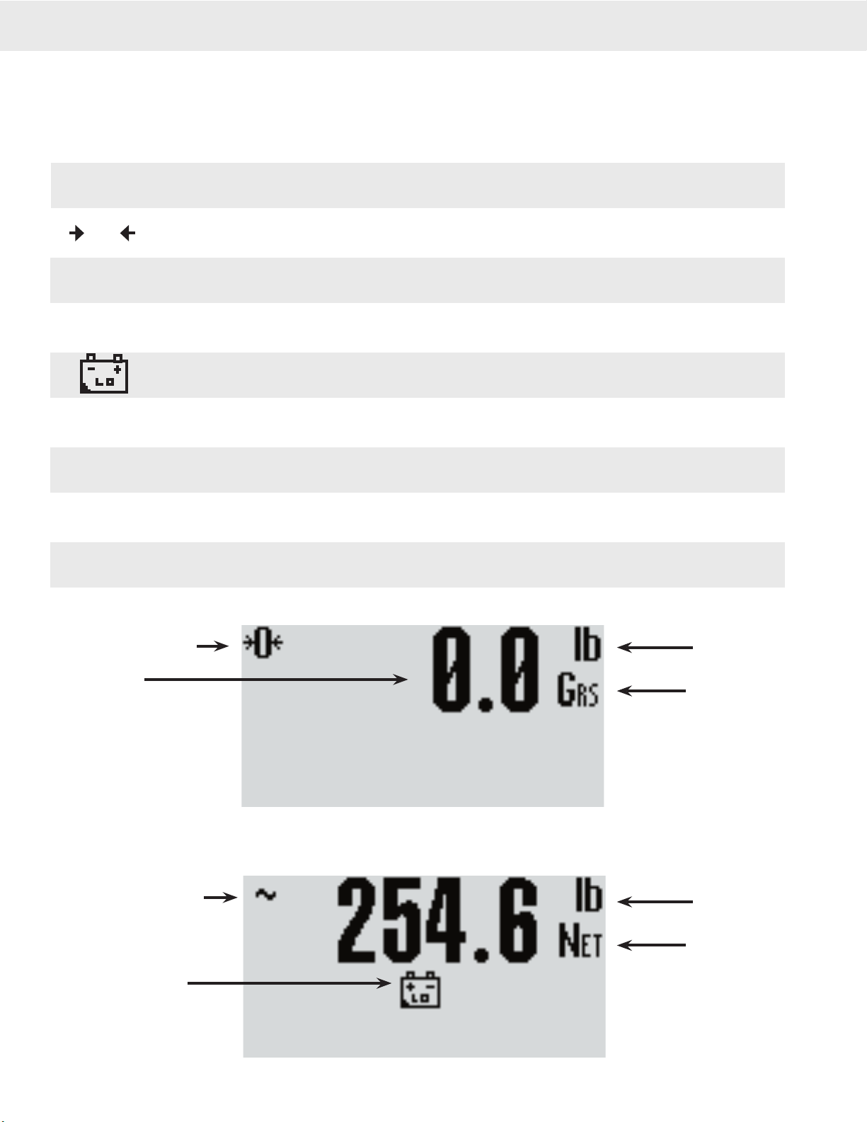
9750A DISPLAY SYMBOLS
The 9750A uses a full dot matrix graphics display which allows 3 sizes of fonts and full use of graphic symbols.
On standard single channel and multi-channel displays, certain symbols are used for scale specific indications.
The motion symbol indicates that the weight has not settled within the motion window (usually ±1d). While this
symbol is illuminated, the scale will not zero, tare, or totalize.
Center-of-Zero – Indicates the weight is within 1/4d of zero. In the small font it appears as “>0<”.
The Sigma symbol is used to indicate a total weight
GRS – Abbreviation for Gross Weight
Low Battery Symbol – Appears when approximately 10% of battery life remains. The 9750A places the indicator
in various locations depending on the display mode
ton– Indicates US short tons equal to 2000 lb.
tne – Indicates metric tons equal to 1000 kg.
daN – Indicates the force measurement unit dekaNewtons.
Dashes indicate data not yet received from the CellScale, or the RF network is disconnected.
O
~
∑
GRS
ton
tne
daN
Center of Zero Indicator
Weight Display
Scale in Motion Indicator
Low Battery Indicator
Units Indicator
Weight Mode
(Gross, Net, Tare)
Units Indicator
Weight Mode
(Gross, Net, Tare)
------––
Typical weight displays showing the use of common symbols

MSI CellScale® System • 9750A User Guide Page 7
MEASUREMENT SYSTEMS INTERNATIONAL
Firmware Version 2-XX
GENERAL INFORMATION
The 9750A is a versatile indicator capable of displaying many data items. As a member of the CellScale family
the 9750A does not stand alone. It is a slave device to a MSI-9000 CellScale. All data displayed on the 9750A is
received via RF from a master CellScale. Many menus in the 9750A depend on information from the CellScale.
Therefore, turn the CellScale on before using the 9750A.
Due to the high data rates in the CellScale system menus usually respond instantly. However there are times
when the CellScale is busy and it will not “service” the 9750A instantly in all circumstances. At these times you
may see the word “Pending” or dashes, or data placeholders which will indicate the CellScale has not yet sent
the required information. Weight displays have priority and are sent before all text strings are updated (such as
channel name, ID name, etc.).
The majority of CellScale installations have only a single scale input. In this case the Multiple Display modes
are not needed. However, even with only a single scale input, Math Channels are available which can be applied
for specialized applications.
MANUAL & 9750A CONVENTIONS
1) Keys used in operations are printed in GRAY and capitalized.
2) Setup procedures are usually shown with the shortcut method of reaching the menu. All menus can also be
reached through the “Setup Select Menu”. Use the [7] key to see all available menu choices.
3) Screen shots are shown for example. Many screens provide additional information to orient the user to the
scale channel, or ID, or selections made. For example, the Function Key Setup menu will show you the current
selection for each key. When you change the function, the previous menu changes to reflect your choice.
4) If a function key does not work, it is probably because the CellScale is not setup to support the key. For
example, if only one channel is defined in the CellScale, pressing the CHANNEL key will have no effect.
This also applies to the ADDRESS key. If only one Network has been defined, the ADDRESS key has no
other Network to log onto.
5) Menu Titles are shown at the top of the LCD screen and are fully capitalized.
6) When space permits, selected parameters are shown at the right side fully capitalized.
7) Submenus with multiple choices use a highlighted arrow “4” to indicate current choice(s).
8) When in menus, the ESC key (same as SETUP) drops back one menu level.
9) When in Setup Menus, the DISPLAY key returns you directly to the Weight Display (Exit mode).
10) Cursor Keys (alternate functions of F1, F2, F5 and F6) only function in menus. Use the DOWN (v) cursor
key to enable the cursors then use the UP (^) or DOWN (v) cursor to select line items. Use, ENTER, LEFT
(<), or RIGHT (>) cursor keys to rotate through menu choices or select the associated submenu.
11) If a submenu is associated with a menu choice, either highlight the menu choice with the cursor keys and
press ENTER, or press the numbered key corresponding to the desired menu item.
12) If a menu applies to any channel, pressing the CHANNEL key will select the next channel in the CellScale’s
scan list.
13) If a menu applies to any ID, pressing the ID key will select the next ID in the CellScale’s ID list.
14) To input, for example, an ‘E’, first use the ALPHA key to change to alpha mode, then press [2] twice. If you
need two ‘E’s, pause briefly until the display cursor has moved to the next position, then press [2] twice.
15) In single display modes, pressing the ENTER key highlights the whole display to indicate the next press of
a Function key will use the alternate mode (Enter-Function Key).
Page 8 MSI-9750A RF Remote Indicator • User Guide
9750A HANDHELD RF REMOTE INDICATOR for CELLSCALE
®
FEATURES
• Designed to meet or exceed all US and international standards.
• Multiple Customized Display Modes, single channel or multiple channel modes
• Reliable 2.4 GHz Frequency Hopping RF communications. Highly immune to interference and multi-path
problems. Range in excess of 500 feet indoors and over 5 miles (line of sight) with proper antennas.
• Each 9750A can act as a terminal for any CellScale. A 9750A can monitor multiple scale channels on a single
CellScale, or multiple scales tied to multiple CellScales.
• Store up to 32 per connected CellScale ID Codes with separate Alphanumeric Names, Tare, Mode, and Totals.
ID Codes are addressed by any customer given name or number. Two user entered ID data strings are available
for each ID code.
• Easy to read annunciation of ID Names and Menu Prompts are provided on the fully customer defined display
screen.
• Full RS-232 output formatting offers exceptionally versatile data output. Weight data can be printed in any
desired way. The customer can add any alpha characters and/or printer formatting commands; including for-
matting for Bar Code printers. Bar Code readers can also be attached to the Comm Port.
• Manual or Automatic Data Logging into battery backed memory. Any data can be stored for later downloading
into a computer.
• Display illumination uses rugged, long life, LED backlighting coupled with a transflective LCD to provide
optimum display contrast under all ambient conditions from full sunlight to total darkness. The backlight
automatically turns off and on when needed to conserve battery life.
• NiMH battery pack provides up to 9 hours of continuous operation. The built in charger operates, with the
proper adapters, from 90-260 VAC (45-65 Hz), or 12-24 VDC Input (optional Cigarette Lighter Adapter avail-
able). Accessory power supplies are available to allow charging from 250 VDC as well.
• Selectable for lb., kg, g, tons, metric tons, ounces, and daN for force measurement (some units and /or units
switching may be prohibited in legal for trade units).
• Multi-mode automatic or manual weight totalizing with multiple ID registers.
• Weather resistant sealing ensures reliable operations under harsh conditions. Rugged, gasketed, PVC package
is rated to NEMA 3 and IP54.
9750A BLOCK DIAGRAM

MSI CellScale® System • 9750A User Guide Page 9
MEASUREMENT SYSTEMS INTERNATIONAL
Firmware Version 2-XX
THE CELLSCALE FAMILY
1) Model 9000 CellScale – Rugged unit for interfacing any scale and converting it to RF networking.
2) Model 9008 Multiplexer – Allows up to eight scales with independent calibrations, to share a single CellScale
input channel.
3) Model 9020 CellModem – For interfacing peripheral devices to a CellScale.
4) Model 3750CS – Fixed mount indicator for CellScales. Capable of control and calibration.
5) Model 9750A – Portable remote indicator for CellScales. Capable of control and calibration. Can display
multiple channels.
6) Model 9300 – CellScale based Crane Scale with local LED display.
7) Model 6260CS – CellScale based Crane Scale. Available in standard capacities up to 100000 lb (50000 kg)
and by special order up to 250 tons
Model 9260 – (Not pictured) Motion Compensated Crane Scale used in scrap metal weighing.
Model 9002 Summing Box – (Not pictured) Single or Dual Channel summing of up to 4 load cells.
1
23
4
5
6
7

Page 10 MSI-9750A RF Remote Indicator • User Guide
9750A HANDHELD RF REMOTE INDICATOR for CELLSCALE
®
UNIT SETUP
The 9750A is simple to setup and use. If there are no peripheral devices such as a printer or bar code scanner,
setup consists of charging the battery, and setting the modem controls to talk to a 9000 CellScale.
BATTERY
The 9750A uses a high capacity Nickel Metal Hydride Rechargeable battery pack. The battery pack will power
the 9750A for up to 8 hours depending mainly on how much the LCD backlight is on. This is a custom battery
pack with over-temp and over-current protection designed for fast charging that must be replaced with MSI P/N
12431. The battery pack should last over 500 charge cycles. NiMH batteries do not suffer from memory effects
and can be charged at any time in the discharge cycle. NiMH batteries do have a fairly high self-discharge rate,
so if the unit is unplugged and idle for a long period of time, the batteries will require charging.
The 9750A LCD will display a low battery warning when there is about a half hour to an hour (depends on back-
light and battery age) of operating time remaining.
REPLACING THE BATTERY
The 9750A is shipped with the battery pre installed. When the battery needs replacing, remove the 6 screws on
the back panel to gain access to the NiMH battery. Gently pull out the battery cable from the interior of the case.
There is a single latch on the connector that must be pushed to separate the battery cable from the 9750A. After
plugging the new battery in, stuff the connector back into the case interior, then reseal the battery cover.
CHARGER ADAPTER
The 9750A battery charger is integral to the 9750A. Input power can any source of 12-24VDC with a minimum
of 20 watts of power. MSI provides two charger sources: 1) Universal AC power: Operates from 86 to 265 VAC
45 to 440 Hz. 2) Vehicle Power: Works with vehicles with 12-24 VDC battery systems (cigarette lighter adapter).
The maximum drain on the power source is 20 watts, but this amount of drain is brief. The source current tapers
down as the battery charges. For 12V systems the maximum drain is about 1.5 amps. A 5A fuse is sufficient to
protect the vehicle electrical system while still providing enough peak power to charge the battery. The MSI
Cigarette Lighter Adapter (MSI P/N 12674) is internally fused with a 5A fuse.
CHARGING THE BATTERY
Turn off the 9750A. Plug in the Charger Adapter in the charge port. Charging will take up to 2 hours depending
on how much the battery was discharged. The 9750A has a charge status indicator on the front panel. The charger
is in fast charge mode when the light is Red. When the light turns Green, the 9750A is ready for use.
Charge Indicator
Off External Power Not Present
Blinking Red/Grn Charge Pending. Either the battery temperature is too high, or the cell voltage is below what
is safe to fast charge. The battery is trickle charged until these conditions are cleared.
Steady Red Fast Charge in progress.
Green Fast Charge Completed. Charger enters pulse phase charge top off. You can use the system
as soon as the green light is on. However, maximum charge capacity is reached about 30
minutes after the light turns green. The Green light will pulse often while in top off phase,
less often during maintenance phases.
When the battery is new, charge the battery for at least 2 hours initially. Then unplug the
adapter, let it cool for 1/2 hour, and then plug it back in. This will initiate another fast
charge cycle that should only last a short time if the battery is functioning properly.
The internal charger is a multi-stage charger. The external adapter can be left plugged in indefinitely. It will
continually pulse charge the battery preventing self discharge and keeping the battery topped off. If the 9750A is
used sporadically, MSI recommends leaving the adapter plugged in while the system is idle.
Do not operate the 9750A with the adapter plugged in. The charger will not charge the internal battery. To ensure fully charging the
battery, turn the 9750A off, remove the power plug, then plug it back in.
!

MSI CellScale® System • 9750A User Guide Page 11
MEASUREMENT SYSTEMS INTERNATIONAL
Firmware Version 2-XX
SECTION 2 – RF SCALE COMMUNICATIONS – THE CELLSCALE SYSTEM
The 9750A is a component of the MSI CellScale System. The CellScale system uses frequency hopping
spread-spectrum RF Modem technology transmitting in the 2.4 GHz ISM band.
RF Modems have been problematic as the RF bands are very hostile, corrupted by noise, path loss and inter-
fering transmission from other radios. Even in a pure interference-free environment, radio performance faces
serious degradation through a phenomenon known as multipath fading, a problem particularly prevalent for
indoor installations. Multipath fading results when two or more reflected rays of the transmitted signal arrive
at the receiving antenna with opposing phase, thereby partially or completely cancelling the desired signal.
Spread spectrum reduces the vulnerability of a radio system to both interference from jammers and multipath
fading by distributing the transmitted signal over a larger region of the frequency band than would otherwise
be necessary to send the information. This allows the signal to be reconstructed even though part of it may be
lost or corrupted in transit.
Spectrum has been set aside at 2.4 GHz in most countries for the purpose of allowing compliant spread spec-
trum systems to operate freely without the requirement of a site license. In the USA, there are absolutely no
site licensing requirements. The CellScale system is also programmable for use in most European countries.
Please contact MSI for worldwide compliance information.
FCC STATEMENT
Note: This unit has been tested and found to comply with the limits for a class A digital device, pursuant to
part 15 of the FCC Rules. These limits are designed to provide reasonable protection against harmful interfer-
ence when the equipment is operated in a commercial environment. This equipment generates, uses, and can
radiate radio frequency energy and, if not installed and used in accordance with the instruction manual, may
cause harmful interference to radio communications. Operation of this equipment in a residential area is likely
to cause harmful interference in which case the user will be required to correct the interference at his own
expense. Commensurate with EIRP limits specified in FCC Rules 15.247b, this device may not be used with
antennas that exceed 36dB of gain in point-to-point applications or 16dB of gain in multi-point applications.
The Transmitter Module is licensed as FCC ID: HSW-2400M.
NETWORK DESCRIPTION
The CellScale system uses frequency hopping which is produced by transmitting the data signal as usual, but vary-
ing the carrier frequency rapidly according to a pseudorandom pattern over a broad range of channels, in this case
80 discreet frequencies. These 80 frequencies are combined in different “hopping patterns” to provide 16 separate
networks. With minor degradation in channel throughput, this can be doubled to 32 separate networks. The original
16 networks are numbered 00-15, the secondary networks are numbered 16-31. While it is possible to have all 32
networks commingled, some data rate degradation may occur between networks 16 channels apart (e.g. Network
00 and 16, 01 and 17, 02 and 18, etc.), although in most situations this degradation will be unnoticable.
The CellScale network uses a ‘Star’ network topology. One unit, usually the CellScale, is designated a ‘Master’.
The Master transmits a sync pulse on a regular basis, providing synchronization of all remotes in the designated
Network. MSI provides five products capable of being the master unit: the CellScale, the Smart CellModem
9000 (not 9020), the MSI-9260 ruggedized Crane Scale, the MSI-9300 Porta-Weigh+ Crane Scale (with local
display), or the MSI-6260CS Trans-Weigh CS Crane Scale. Up to 15 slaves can access the master unit. The
9750A is always a ‘Slave’. Multiple 9750A units can coexist on one network, or can be easily switched to other
networks as required.
The CellScale system uses CSMA (Carrier sense multiple access) to arbitrate between multiple remotes. CSMA
is contention-based. Each remote listens to see if the channel is clear and then transmits. If the channel is not
clear, the remote waits a randomly chosen period of time and then tries again. For more on setting up CellScale
networks, please refer to the MSI-9000 CellScale User Guide.
ANTENNA
The 9750A uses a built in “Patch” antenna with no external visible element. The patch is located in the end of the
9750A above the display. In most installed CellScale networks, the patch antenna is essentially omnidirectional.
However, in systems where the 9750A is reaching the limits of transmission range, the 9750A will achieve better
range by pointing it toward the master CellScale’s antenna.
Page 12 MSI-9750A RF Remote Indicator • User Guide
9750A HANDHELD RF REMOTE INDICATOR for CELLSCALE
®
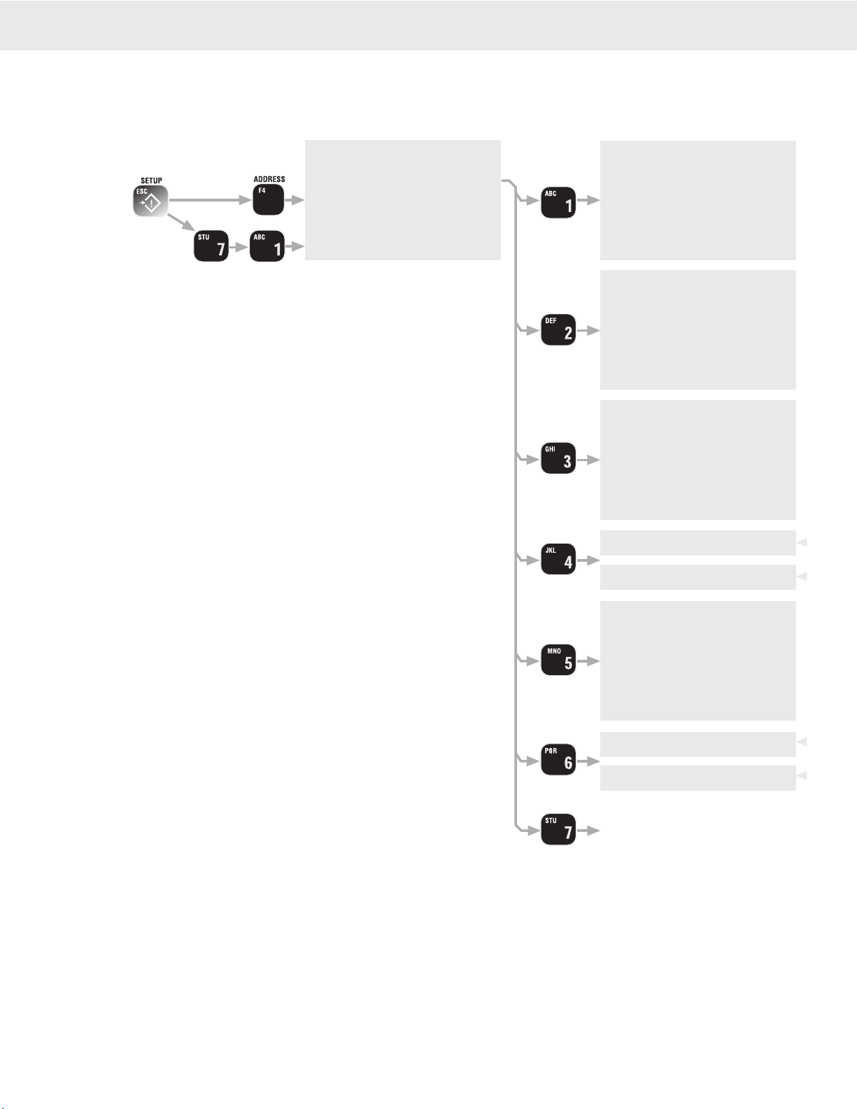
RF NETWORK SETUP
The 9750A is a RF Modem connected device. The RF Modem requires setup to connect to one or more CellScales.
The 9750A stores information for all 32 possible networks. Each network setting can be modified with the “Modem
Settings Menu”.
17
17
57
1Ø
[1] NETWORK ADDRESS – Sets the primary network
address number. Set this number to match the Network
number of the CellScale master the 9750A must com-
municate to. Ranges from 0 to 31.
[2] CS ADDRESS – Sets the primary master CellScale ID
number. This number must match the Source Address
number of the primary master CellScale. Ranges from 0
to 254. This number is usually, but not always, the same
as the Network Address.
[3] MY ADDRESS – Any 9750A unit in a given Network
must have a unique ID number. Enter up to three digits
to designate the 9750A ID number. Ranges from 0 to
254. Make sure no other devices have this same number.
Other devices that must have unique numbers are 9020
Modems, 3750CS Indicators, and 9300 and/or 6260CS
crane scales used as slave units.
[4] TRANSMIT POWER – Sets the RF power level between
10 mW (Lo), and 100 mW (Hi). In most applications
power should be set to High. Reduced energy can reduce
the size of the coverage / interference zone which may
be desirable for multiple-network applications. Always
check for adequate range coverage when using the Low
setting. Only a minor improvement in battery life (~10%)
is achieved by using the Lo setting.
[5] TIMEOUT – Sets the time in seconds (0-1800) that the
9750A will wait for data from the CellScale Master. The
display will blank out if no data is received within this
time period. MSI recommends at least a 10 second time
out period to handle small lapses in transmissions. The
system defaults to 10 seconds.
[6] SCAN NETWORK – Setting the Scan Network ON
places the network in the list of addresses reached by
pressing the ADDRESS key. Setting the Scan Network
OFF still allows you to pre configure the network set-
tings, but the Network will not be in the list of available
networks.
[7] SAVE SETTINGS – Commits the settings to the Modems
Memory. The Modem settings will be automatically
saved at power down if changed.
MSI CellScale® System • 9750A User Guide Page 13
MEASUREMENT SYSTEMS INTERNATIONAL
Firmware Version 2-XX
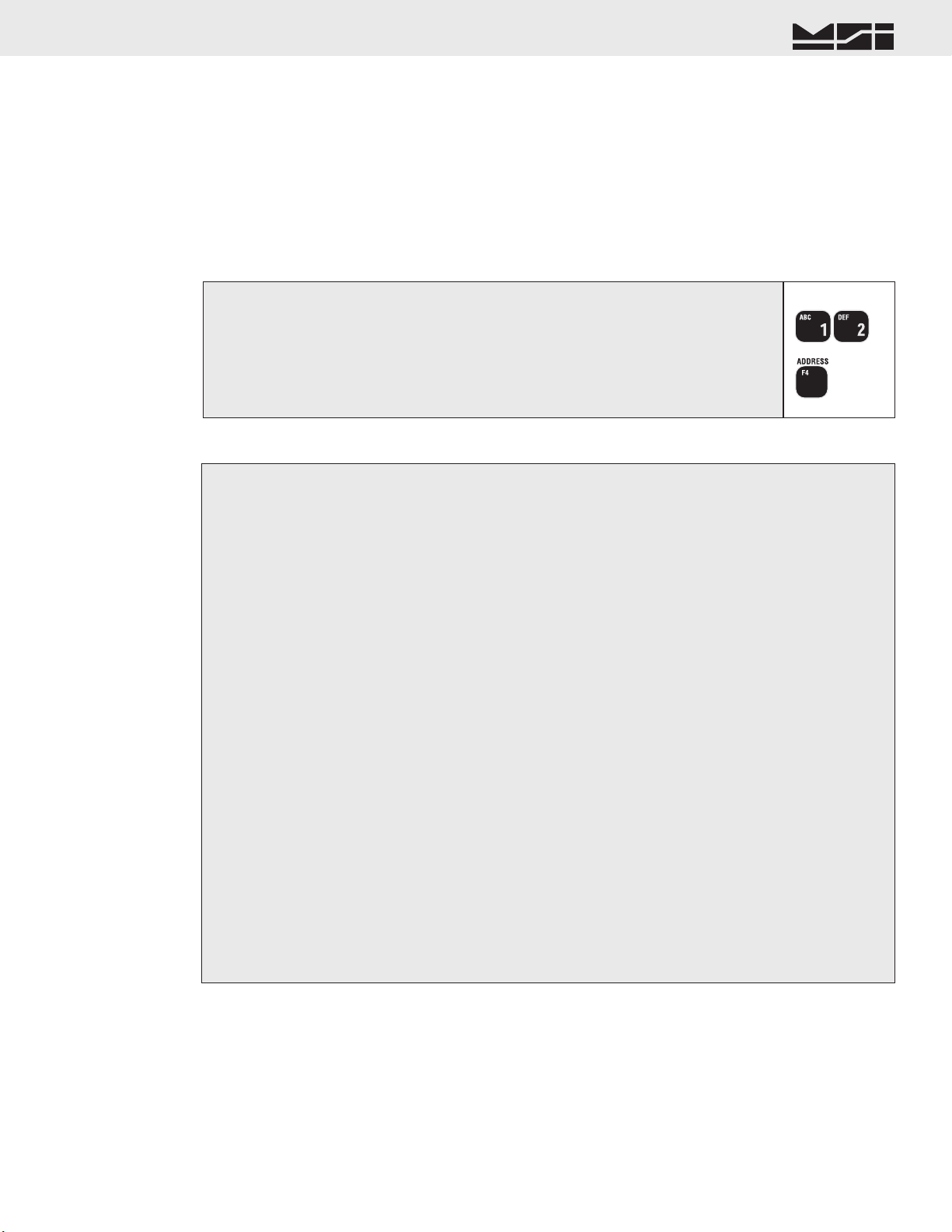
1) Enter the number of the CellScale network.
In this example we’ll use network 12. Use the appropriate numbers for your CellScale master. It is not necessary to enter a ‘0’
for networks below 10.
2) Press the ADDRESS key. The Network Address Changes to the new Address and is
added to the Network Scan List.
It can take up to 8 seconds to log on to a new network, and for the weight data to appear. If the 9750A is unable to locate a
Master CellScale at the entered address, the message “NO NETWORK” will appear.
1
2
Setting the Network Address (shortcut method)
Uses Defaults for every setting, and assumes the master CellScale’s ID is the same as the Network Address, i.e. 12-12 or 02-02.
1) Press SETUP. From the “SETUP SELECT MENU” , select “MORE” [7].
2) Select “RF Modem” [3].
Steps 1 and 2 have a shortcut. Press SETUP followed by ADDRESS.
3) Select “Network Address” [1]. This calls the Network Address data entry screen.
4) Using the keypad, key in the desired Network Address (0-31). The Address used must match the Network
address of the CellScale master. Press ENTER to store the address.
5) Select “CS Address” [2]. This calls the CellScale Address data entry screen.
6) Using the keypad, key in the desired CellScale Address (0-254). The Address used must match the ID
address of the CellScale master (2nd number, e.g. xx-12. Usually CellScale masters are configured with
the ID Address number matching the Network Address number.
7) Select “My Address” [3]. This calls the My Address data entry screen.
8) Using the keypad, key in the desired My Address (0-254). The Address used must be unique within all
possible networks this 9750A is to contact. Press ENTER to store the address.
9) Select HI or LO transmit power using the [4] key. Usually this should be set to HI for maximum range.
10) Select Timeout [5].
11) Using the keypad, set the Timeout in Seconds. A timeout from 5 to 20 seconds is recommended (10 seconds
is the default). Press ENTER to store the timeout.
12) Set this network active by pressing [6]. This places the Network in the 9750’s active network list, allowing
use of the ADDRESS key to switch the 9750A to this and other stored Modem settings.
13) Store the Modem settings by pressing [7]. The unit will pause with a key tone while the settings are
stored.
14) Return to weight reading (assuming there is a CellScale at the address you just set) by pressing DISPLAY
or press ESC to return to the Setup Menu. There may be a delay while the new address request is processed
by the CellScale.
Setting the Network Address (standard method), and RF Modem Configuration
Access to all user configured parameters in the RF Modem.
Modem Defaults
CS Address equals entered Network Address (e.g. 12-12, 1-1, 9-9, etc.)
Transmit power set to HI.
Time out set to 10 seconds.
My Address remains unchanged and is the same in any network.
CONFIGURING FOR MULTIPLE NETWORKS
The 9750A can access multiple CellScales by switching Networks. A press of the ADDRESS key will change the
network allowing the 9750A to monitor and control different scales. Because each CellScale has both a network
and a CS address, these must be set up with the “SETUP RF NETWORK” menu and made active. The 9750A
can access up to 32 CellScale based Networks. It takes the 9750A from 4 to 8 seconds to switch networks, as
it has to sync with a new hopping pattern. Networks that are inactive but were set up can be reached by typing
the Network Address (0-31) followed by the ADDRESS key. New networks not previously set up can also be
reached this way, but the modem configuration will set to defaults.

Page 14 MSI-9750A RF Remote Indicator • User Guide
9750A HANDHELD RF REMOTE INDICATOR for CELLSCALE
®
TROUBLESHOOTING RF CONNECTION PROBLEMS
Most connection problems are caused by improperly set up RF Networks. Both the 9750A and the master CellScale
unit must have identical Network numbers. In addition, the CS Address must match on both units. If the Net-
work and/or CS Address of the CellScale is in question, you might have to connect a terminal to the CellScale to
determine its exact settings. See the CellScale manual for this procedure. Verify the 9750A settings are proper
by using the “CONFIGURE RF MODEM” procedure. Each slave device (9750s, 3750CS, and 9020s) must have
unique “My Address”.
A common cause of perceived problems is the “Phantom Network”. This occurs when there is a conflicting Net-
work within broadcast range. Multi-CellScale sites must be planned carefully so that there are never two master
CellScales on the same Network within range of each other. Since the CellScale can broadcast for miles with
good LOS (line of sight) conditions, this consideration is very important. If you suspect your 9750A has locked
on to a distant (Phantom) network, try switching both the master CellScale and the 9750A slave to another unused
Network. MSI advises avoiding Network #0 when possible, as this is the Modem default, and therefore most
likely to be found on units that were left in default settings.
Weight displays, but 9750A keys don’t work
This is a result of changing the CS Address in the slave 9750A so it no longer matches the master CellScale. The
modem is still registered by the master CellScale, but control codes are not received because the master assumes
the codes are intended for a different slave CellScale. Change the CS Address in the 9750A back to the number
that matches the master CellScale.
Unit goes in and out of communication
This is usually a result of being in or near an “RF Null” zone. Because of multiple echoes of signals there is
sometimes locations that are particularly problematic even for Frequency Hoppers. Usually moving the antenna
location even a small distance can clear up this kind of problem. Avoid placing the antenna up against large metal
walls. Concrete walls can also be problematic due to their high moisture content. The antenna should be at least
4 inches away from large metal or concrete surfaces. Mounting the antenna too close to a wall has the effect of
making the Antenna directional and can attenuate the output.
Range is Inadequate
Antenna placement is the most common cause of poor range. Check that the RF power level of the master and
slave units is on “High”. Radio signals in nearby bands that have significant power can also reduce range. Lon-
gest range will always be achieved by Line-of-sight (LOS) antenna placement. Any obstacle that interferes with
LOS will reduce the range. Significant blocking is caused by metal buildings, solid concrete walls, and any other
object that has fairly high electrical conductance. Raising the master antenna higher can help. Just moving the
relative antenna placement a short distance might find an RF “path” that will improve distance. The CellScale
can sometimes take advantage of reflecting surfaces to get around obstacles. CellScale device antennas should
always be placed in vertical polarization; that is the shaft of the antenna should be perpendicular to the earth,
not parallel. It is OK to mount the Antenna upside down. This is a good solution when an antenna is mounted on
the ceiling for communication with CellScale components in the building. The 9750A internal antenna is mildly
directional. Aim the end of the 9750A towards the CellScale master for longest range. In short range applications
(LOS and <500 feet) the 9750A is essentially omni-directional.
Some CellScale master units can take advantage of higher gain antennas.Yagi Antennas can greatly improve the
range of a CellScale system when installed on the master CellScale. These multi-element antennas are highly
directional and must be aimed towards the 9750A area of operation.
The CellScale system is designed using state of the art RF Modems. However there will be conditions and envi-
ronments where communication of telemetry is sporadic or impossible. Jamming of FHSS systems is difficult,
but not impossible. Bear in mind that the most likely source of jamming will be other CellScale systems on the
same network, within transmission range. The new breed of wireless phones (not Cell Phones) operating in the
2.4GHz bands will not jam a CellScale. However the CellScale may be received on the wireless phone and will
sound like a background ticking noise. Standard Cell Phones do not operate in the same bands as the CellScale and
will not interfere with CellScale components. However, a Cell Phone repeater tower nearby might have enough
out of band interference to reduce the range of CellScale equipment.

MSI CellScale® System • 9750A User Guide Page 15
MEASUREMENT SYSTEMS INTERNATIONAL
Firmware Version 2-XX
1) Place the 9750A in close proximity of the master CellScale unit. Make sure communications are good
(weight is on the display, all data types have been reported).
2) Press the function key programmed for “RF Site Testing”. The bottom right side of the display will read
“RF xx%”. The per cent reading indicates the ratio of successful transmissions. It will start low at first,
then creep up. It should approach 100%, with an average reading of >96%.
If the reading does not achieve >96% within 1 minute try changing the CellScale Master device (MSI-9000, MSI-6260, MSI-9300, etc.) to a new network.
Usually the only thing that will interfere with a CellScale is another frequency hopping modem nearby. Also check your antenna connections on the
master.
3) Now start walking around the site with the 9750A. If the RF% reading starts down, stop and wait. Aim the
9750A towards the CellScale master and see if the RF% reading begins to rise again. If the display suddenly
reads “NETWORK”, you have lost communication. Return to the last place that communications were
working and wait for the 9750A to reconnect. In this way you can establish the range of adequate com-
munications, and note any areas with severe RF dropout. The location and height of the CellScale master
also plays a big part in range so be sure to run the site test with the CellScale in typical locations used in
your application.
4) Cancel the RF Site Test by pressing the function key again. If needed for some other function, reprogram
the function key.
RF SITE TESTING
The 9750A provides a means to check the efficiency of RF transmissions using the RF Site Testing function.
Program a function key (use the procedure in Section 4) to “RF Site Testing” to run the test.
CELLSCALE NETWORK AUTO SCAN
For installations where multiple CellScale systems are present, the 9750A can scan every network and determine
if a CellScale master device is broadcasting. Found CellScales can be copied directly into the RF Scan List at the
end of the test. Turn on all CellScale masters (MSI-9000, 6260CS, 9300, etc.) that your 9750A will be used with.
Ensure that each CellScale master is on unique network addresses (see product User Guides).
1) Press POWER followed quickly by ESC.
It doesn’t matter if the 9750A is on or off.
2) Press NET/GROSS to start the scan. The 9750A will begin a progressive scan of all 32 networks.
The scan can take as long as 15 minutes. If the backlight times out, press any number key to turn it back on.
3) Every CellScale master found will display along with its address. The end of the test will be indicated by
the display reading “ENTER Copy to Scan”.
4) If you want to store the found CellScale addresses, push ENTER. The display will read “COPYING RF
SCAN”.
5) Press DISPLAY to return to weight reading.
You can also press SETUP which will bring up the Setup Menu, or POWER which will turn the 9750A off.
Page 16 MSI-9750A RF Remote Indicator • User Guide
9750A HANDHELD RF REMOTE INDICATOR for CELLSCALE
®
SECTION 3 – SCALE OPERATION
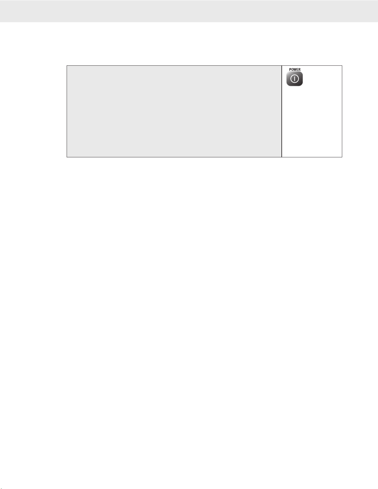
POWER
To Turn On the Power
If the system fails to con-
nect in 8 seconds or less,
press the ADDRESS key to
select a different Network,
or enter the number of a
working network and press
ADDRESS. If this fails
check RF network setups,
or decrease the range
between the CellScale and
the 9750A.
1) Press and hold POWER for 1 second. The system Shows the MSI Logo followed
by a graphic of a Model 9000 CellScale.
2) The LCD then displays “MSI-9750A”, the Network currently loaded as the active
Address, and the software version number. The display may read “SCANNING”
while establishing communications with the master CellScale.
3) Next the RF network is contacted. If the network is functional, the display switches
to normal weight display mode. This usually takes 4-15 seconds. If the Network
is not available, the screen will continue to display the desired Network. Either
change the Scan Network with the ADDRESS key or turn on the proper CellScale
Master. Use of the ADDRESS key assumes that multiple networks have previ-
ously set up. See “Setting the Network Address” on page 12.
MULTIPLE SCALE CHANNELS
Each CellScale is capable of hosting up to 32 independent scale inputs. Since any 9750A can communicate with
any CellScale, theoretically hundreds of scales can be controlled by a single 9750A. Because of the complexi-
ties of multiple channel setups, the 9750A is designed to access channels that have been previously setup in the
CellScale through its terminal interface or virtual meter interface.
Channels in the CellScale are organized by the A/D input channel followed by a Mux sub channel value. The
standard CellScale has two A/D inputs, but can be ordered with four A/D inputs with the addition of a second
A/D Converter module. Each A/D channel can be further divided by the use of external multiplexers into eight
additional inputs per channel, providing a total of up to 32 independent scale inputs. The channels are designated
like this:
Channel (A/D 1-4) → 1-1 ← Sub channel (mux 1-8)
The channel will vary from 1-4 and the sub channel from 1-8. In addition the CellScale provides channel 5 for
slave CellScales, and channel 6 for math channels. Math Channels allow the user to add or subtract channels from
each other or perform other mathematical manipulations of the data. All calibration data for the 32 channels is
stored in the CellScale and is independent of the 9750A. Therefore any 9750A can receive calibrated data from
any CellScale provided the RF network is set up properly.
It should be noted that sub channels are useful even when the multiplexer option is not used. For example, chan-
nel 1-1 could be calibrated as a 1000 x 0.5 kg scale, and channel 1-2 as a 2000 x 1 kg scale, making a dual range
platform (of course this assumes the platform is capable of handling 2000 kg). This will work as long as the main
channel remains constant. So, in theory, 1 platform could be calibrated as 8 independent scales. This works because
the CellScale does not know or care if a Multiplexer is actually present. It treats the input as a separate scale.
The 9750A reads multiple channels by using the Scan list index. The “Scan list” is stored in the CellScale, with
up to 32 channels present in the list. The first number in the scan list is called the Scan List Index number. The
CellScale can have up to 32 Scan List indices. A scan list can include “Math Channels” which provide a means
to digitally add the results of multiple scales.
When dealing with multiple channels it is recommended that you set up the display to always show either the
Channel Number or the Channel Name or both. This will help in identifying which scale you are observing.
SELECTING THE ACTIVE CHANNEL
Before standard scale functions are performed, you must select the “Active Channel”. The “Active Channel” is the
channel that commands such as Zero, Tare, Total, etc. will be performed on. On single channel display screens,
the channel shown is the active channel. On Multiple channel displays, you must highlight the desired channel.
This is done with the Cursor Keys. Once highlighted you can perform all the standard scale functions (except
Total and View Total, these only work from the single channel display). You can also switch to the single channel
display by pressing the DISPLAY key.
See the “DISPLAY MODE SETUP” section 7 for information on multiple and single channel weight display modes. For more information on Scan Lists and multiple
scale channels, please refer to the CellScale MSI-9000 Users Guide.
MSI CellScale® System • 9750A User Guide Page 17
MEASUREMENT SYSTEMS INTERNATIONAL
Firmware Version 2-XX
1) Press the CHANNEL key [F2]. The weight display will temporarily display dashes while it
queries the CellScale for the next channel information.
2) Keep pressing the CHANNEL key as desired until the channel of interest is displayed.
To go to the previous channel in the list, press the ENTER key followed by the CHANNEL key. (This assumes the default for E2 has not
been altered)
1
2
TO SELECT THE DISPLAY CHANNEL
As mentioned above, the 9750A will access any channels setup in the CellScale. It does this with the “CHAN-
NEL” function. Use the CHANNEL key to step from channel to channel as dictated by the Scan list stored in the
CellScale. If the CellScale has only one scale channel defined, only 1 display mode is necessary. This is usually
the case for MSI-6260CS, MSI-9300 Crane Scales, and other single load cell systems. However, even single load
cell systems can have math channels defined to add functionality.
For systems with multiple scales attached to any given CellScale the setup procedure is:
1) Program the CellScale Scan List as required (see the CellScale Manual). It is recommended that each channel
is assigned a channel name to aid in identifying the scale in various display modes.
2) Optional, but recommended so you can readily identify which scale you are monitoring and controlling
– Program the display mode to show the Channel Name, or Channel Number, or both with the Display Setup
procedures in Section 7.
To Change the Scale Channel (Single Channel Display)
This example assumes F2 is in its default mode CHANNEL.
1) Using the numeric keys, input the number (1-32) corresponding to the desired channel in the
scan list.
This example finds the fourth entry in the scan list. If a requested channel does not exist in the scan list, this procedure is ignored by the
CellScale.
2) Press the CHANNEL key [F2]. The weight display will temporarily display dashes while it
queries the CellScale for the desired channel information.
1
2
To Change the Scale Channel Using Scan List Position (Single Channel Display)
Uses the CellScale’s Scan List Index Number to determine which channel to display.
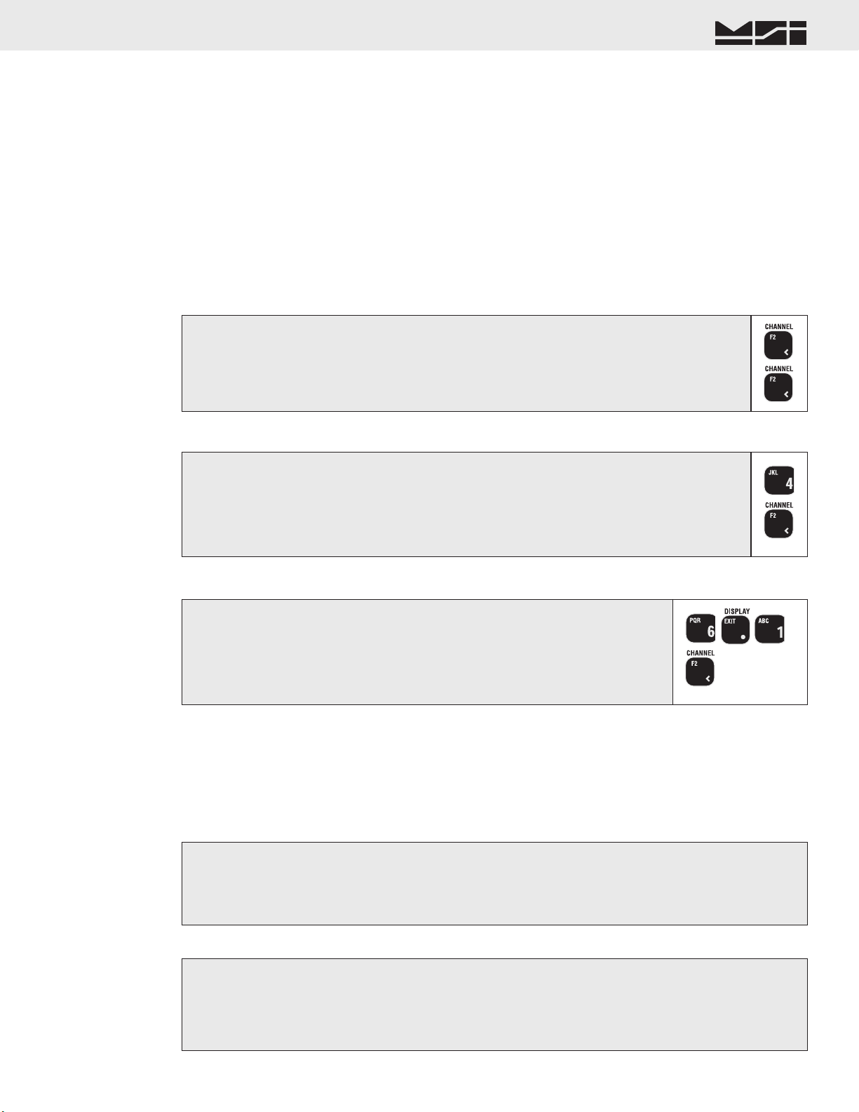
To Change Scale Channel Using the Channel Number (Single Channel Display)
Uses the CellScale’s Channel Number to determine which channel to display.
1) Using the numeric keys, input the number corresponding to the desired channel
number. Use the decimal point as the channel-subchannel separator.
This example finds channel 6-1, a math channel. If a requested channel does not exist in the scan list, this procedure
is ignored by the CellScale.
2) Press the CHANNEL key [F2]. The weight display will temporarily display dashes
while it queries the CellScale for the desired channel information.
1
2
MULTI-CHANNEL SYSTEMS
In CellScale systems with multiple channels, you can choose to see more than one channel at a time (See Display
Setup in Section 7). In order to zero, tare, or totalize with channels in a multiple channel display, you must first
select the channel to operate on. This is referred to as the “Active” channel, because this is the only channel that
any scale function can be performed on.
To Select the Active Channel (multi-channel display)
1) Highlight the channel you wish to make Active by pressing the UP (^) or DOWN (v) cursor keys.
2) Once highlighted you can Zero the channel, set and clear Tare, and switch between Net and Gross with the
NET/GROSS key, just press the appropriate key. For Total, View Total, Statistics and other ID functions,
you must switch the display to the single channel display by pressing DISPLAY.
To Change a Channel in the Multi-Channel Display
1) Highlight the channel you wish to change by pressing the UP (^) or DOWN (v) cursor keys.
2) Once highlighted enter the scan list position (1-32) or the channel number (1-1 to 6-32 using the decimal
point for the sub channel entry). Then press CHANNEL.
The new channel replaces the previous channel. If the channel is already on the display in another location, both will display the same information.
Page 18 MSI-9750A RF Remote Indicator • User Guide
9750A HANDHELD RF REMOTE INDICATOR for CELLSCALE
®
To Switch Between Multi-Channel Display and Single Channel Displays
1) Highlight the channel you wish to see in the single channel mode by pressing the UP (^) or DOWN (v)
cursor keys.
2) Once highlighted press DISPLAY. The highlighted channel will appear in the single channel mode.
3) Perform any scale function while in the single channel mode.
4) To return to the multi-channel display, press DISPLAY.
Multi-Channel Page Display
When a multi-channel display mode is selected that shows fewer channels than are available from the CellScale,
the user can view all channels with the page mode.
Any channel can appear on any page by changing the preset channel using the “To Change Scale Channel...”
procedure. This allows a primary channel to show always, and secondary channels to change using the ALPHA
key. This applies very well to the 3 channel preset display where one channel is large and the other 2 channels
are small.
To Change to the Next Page
Press the ALPHA key. The next group of channels appears. The action of the ALPHA key is circular, return-
ing to page 1 after the last page.
To Copy the Current Page
Sometimes it is advantageous to copy the current page and then make channel changes on the new page.
1) Press the ENTER key. The entire screen will reverse.
2) Press the ALPHA key. The new copied page will appear. Make modifications with the enter channel pro-
cedures as desired.
To Delete the Current Page
1) Press the [0] (SPACE) key.
2) Press the ALPHA key. The current page will be deleted and the display will revert to the first page.
The 9750A will not allow the deletion of the last remaining page.
To Move Around in Pages
If you have many preset pages, you can move directly to pages by number entry.
1) Enter the number corresponding to the page you wish to see.
2) Press the ALPHA key. The new page will appear.
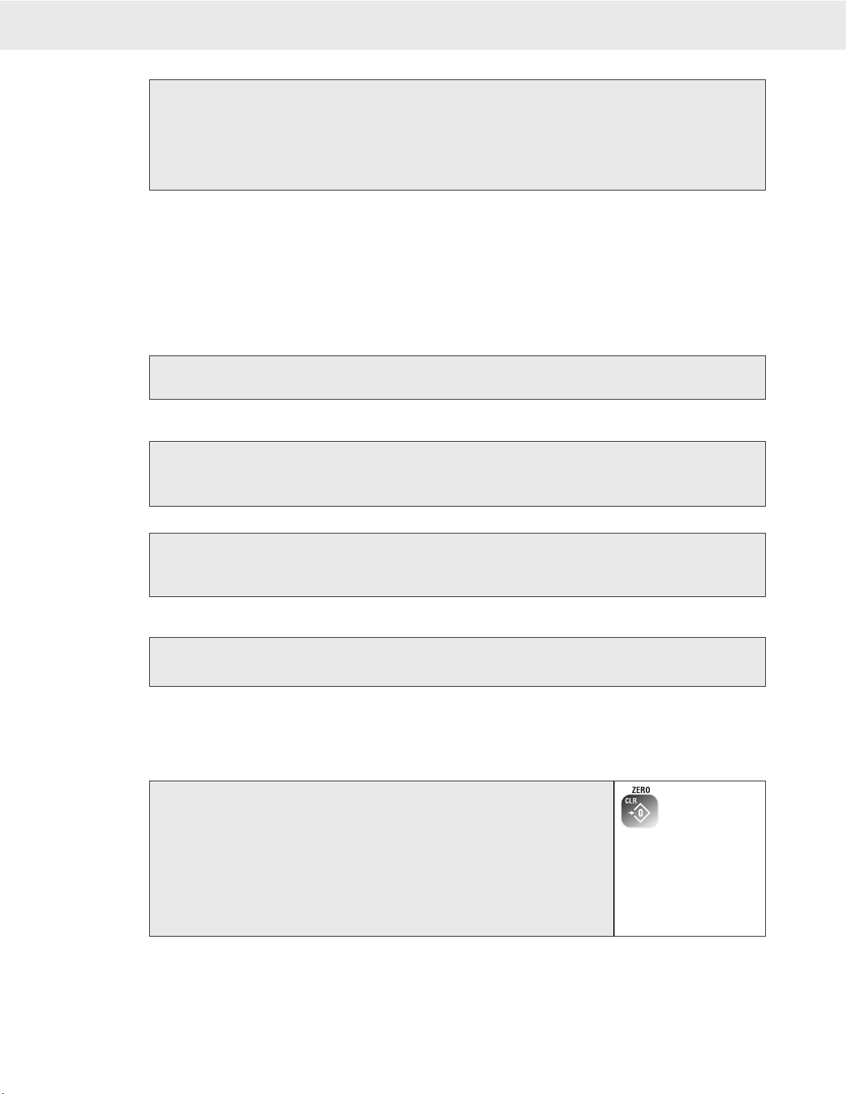
1) In single channel mode, go to step 2. In multi-channel mode, highlight a channel
with the up (^) or down (v) cursor keys to make it active.
2) Press ZERO. The weight reading must be stable within the motion window for
the zero function to work. The display temporarily reads “ZEROING” and then
“ZEROED” after the CellScale acknowledges the command. The scale digits
display 0 (or 0.0 or 0.00, etc..). The backup memory in the CellScale stores the
zero reading, and can restore it even if power fails.
The “ZEROING” and “ZEROED” messages may not be displayed on every zero request if the CellScale responds
instantly, but the scale will zero.
ZEROING
ZEROED
ZERO
Sets the zero reading of the scale. Use the ZERO key to take out small deviations in zero when the scale is
unloaded. (See “TARE SET” for zeroing (Taring) package or pallet weights)
To Zero
Zero Rules for Use:
1) Works in GROSS mode or NET mode. Zeroing while in Net mode will zero the gross weight causing the display
to show the negative Tare value.
2) The scale must be stable within the Motion window. The scale will not zero if the motion detect annunciator
is on. The CellScale will “remember” that it has a zero request for 2 seconds. If motion clears in that time,

MSI CellScale® System • 9750A User Guide Page 19
MEASUREMENT SYSTEMS INTERNATIONAL
Firmware Version 2-XX
the scale will zero.
3) The scale will accept a zero setting over the full Range of the scale (NTEP and other Legal-for-trade models may
have a limited zero range). Zero settings above 4% of full scale will subtract from the overall capacity of the scale.
For example if you zero out 100 lb. on a 1000 lb. scale the overall capacity of the scale will reduce to 900 lb. plus
the allowed over-range amount.
TARE
Tare is typically used to zero out a known weight such as a packing container or pallet and display the load in
NET weight. A Tare value is entered in either of two ways:
1) PUSH BUTTON TARE – When the TARE key is pressed, the current weight is zeroed and Net Weight is
displayed.
2) KEYBOARD TARE – Using the numeric keys, the operator keys in the desired Tare Weight then presses the
TARE Key.
For Pushbutton Tare
To Clear Tare and Revert to Gross Mode
If the goal is to see the Gross Weight, use the Net/Gross key instead.
TARING
1) In single channel mode, go to step 2. In multi-channel mode, highlight a channel
with the up (^) or down (v) cursor keys to make it active.
2) Press TARE. The current Gross Weight will be stored in the Tare register and
the weight mode will change to NET (single display modes).
1) In single channel mode, go to step 2. In multi-channel mode, highlight a channel with the
up (^) or down (v) cursor keys to make it active.
2) Press [0] followed by TARE. The Tare value will clear and the scale returns to the GROSS
mode.
Alternate method: Remove all weight from the scale (Gross Zero) and press TARE. The message display temporarily reads “TARING”.
Then the scale returns to the GROSS mode.
To Keyboard Tare
Tare - Rules for Use:
1) Only positive gross weight readings can be tared. Weight can be tared in both the NET and GROSS modes.
When in the NET mode, the TARE is not cumulative, all the weight is tared off (to Net zero).
2) The motion annunciator must be off. The weight reading must be stable.
3) Setting or changing the tare has no effect on the Gross zero setting.
4) Taring will reduce the apparent over range of the scale. For example, taring a 10 lb. container on a 60 lb.
scale, the scale will overload at a net weight of 50 lb. (60-10) plus any additional allowed overload (usually
~4% or 9d).
5) The scale stores the Tare value in the current ID Code memory until cleared. Each available ID Code can
store independent Tare values.
2
3
1) In single channel mode, go to step 2. In multi-channel mode, highlight a channel with
the up (^) or down (v) cursor keys to make it active.
2) Using the numeric keys input the value desired. In this example we’ll use 0.5 lb. as
a Tare Value. Press [0] [.] [5]. The Enter Line displays “0.5”.
You must place a leading zero if the Tare value is less than 1.
3) Press TARE to place the value in the Tare Register (Current Channel, current ID).
The display reads “TARE SET” when the CellScale responds. All subsequent read-
ings have the Tare value subtracted and are displayed in “NET” weight.
To View the Tare Value
2
1) In single channel mode, go to step 2. In multi-channel mode, highlight a channel with
the up (^) or down (v) cursor keys to make it active.
2) Press ENTER followed by TARE.
3) The display shows the current Tare value
Pressing ENTER again allows the Tare value to be edited.
Page 20 MSI-9750A RF Remote Indicator • User Guide
9750A HANDHELD RF REMOTE INDICATOR for CELLSCALE
®
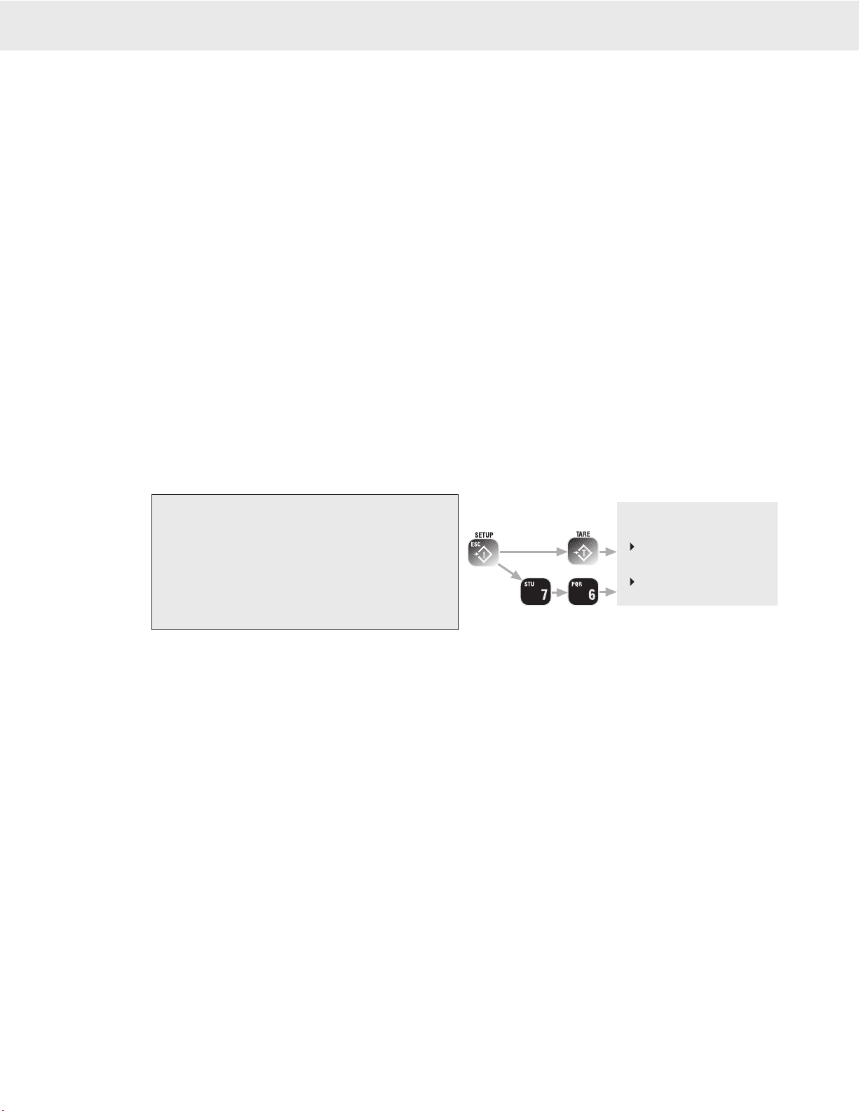
1) In single channel mode, go to step 2. In multi-
channel mode, highlight a channel with the up
(^) or down (v) cursor keys to make it active.
2) Standard Method - Press SETUP. Select
“MORE” [7]. Select “Tare Setup” [6].
Shortcut Method - Press SETUP followed by
TARE.
Multiple Tare Memories
The 9750A is capable of storing Tare values through the use of the ID Codes. Each ID code stores an independent
Tare. See Section 3 “ID Codes” for more information.
SETUP TARE MENU
Programs the automatic TARE Clear function (Auto Clear), and the various Tare Modes including a means to
disable Tare.
1-3 AUTO TARE CLEAR
The Auto Tare Clear is intended to automate loading operations where packaging must be tared out, but there is a
risk that the operator will forget to re tare each new package. It does this by automatically clearing the tare value
and reverting the weight mode back to Gross. The Setup Tare menu permits three modes of Auto Tare Clear: 1)
Disabled. 2) Set Clear on Minus - When the Net Weight goes negative (as it will when a tared package is removed),
the Tare value is cleared and the weight mode reverts to Gross. 3) Set Clear on Total - When the Total function
is enacted, the Tare value is cleared and the weight mode reverts to Gross.
4-5 UNIVERSAL TARE
The Universal Tare feature allows a single Tare value to be shared by all ID Codes. With “Same Tare All IDs”
enabled the individual Tares stored with each ID Code are ignored (but not erased). Selecting “Tare by Product
ID” will restore the original Tare values. Universal Tare is intended for those applications where a common car-
rier or pallet is used, but multiple ID Codes are necessary for data collection. To select Universal Tare choose
“Same Tare All ID’s” on the TARE SETUP MENU. This effects all IDs on any given scale channel, but not the
IDs associated with other scale channels.
Tare Settings Menu
Set Auto Clear Mode with the 1-3 keys. Only 1 item from 1-3 can be enabled at a time. Set the Universal Tare
mode with the 4-5 keys.
1 Disable Auto Clear – Pressing the [1] key turns off the function (default).
2 Set Clear on Minus – When the Net Weight goes negative (as it will when a tared package is removed), the
Tare value is cleared and the weight mode reverts to Gross.
3 Set Clear on Total – When the Total function is enacted, the Tare value is cleared and the weight mode reverts
to Gross.
4 Tare by Product ID – Each ID has a unique Tare when this selection is chosen (default).
5 Same Tare All ID’s – Pressing the [5] key enables the Universal Tare Mode.
NET/GROSS
Switches the display between Net and Gross modes. Net Weight is defined as Gross Weight minus a Tare
Weight.
To Switch Between Net Mode and Gross Mode press the NET/GROSS key.
The NET/GROSS key will only function if a Tare value has been established for the current channel and the Tare
Mode is “NET/GROSS”. The Net/Gross function will affect all meters displaying this channel.
Switching back to Gross mode from Net mode will not clear the Tare value. This allows the operator to use the Gross Mode temporarily without having to reestablish
the Tare value. Only manually clearing the Tare or setting a new Tare will change the tare value held before switching into Gross Mode. In displays that include the
Net and Gross readings, the NET/GROSS key has no effect since both weight types are already displayed. However, other units displaying just one
weight type will change.
OIML Legal-for-trade units only: The NET/GROSS key is temporary action only. The Gross weight is displayed for 2 seconds and then the display
returns to the Net Mode. The only way to return to permanent Gross readings is to clear the Tare (see Clear Tare procedure).
Table of contents
Other Measurement Systems International Accessories manuals

Popular Accessories manuals by other brands

Lennox EMEA
Lennox EMEA FRIGA-BOHN HK REFRIGERATION 3C-E Series installation instructions

Telldus
Telldus 14450 quick start guide

Alula
Alula RE306 Install manual

ORION TELESCOPES & BINOCULARS
ORION TELESCOPES & BINOCULARS 2" Photo-Visual Coma Corrector instruction manual

GHM
GHM Greisinger GTF 101-Ex Series operating manual

Leviton
Leviton T5631 instructions


