Measurlogic DTS 310-3 SB-A Series User manual

©Measurlogic Page 1 of 6
MQ0012-22A
7268 S. Tucson Way, Centennial CO 80112
Tel: 877-777-6567 Fax: 425-799-4780
web: www.measurlogic.com
DTS 310 333mV RS-485 Serial Meter
This Quick Start Guide is designed to familiarize the user with the connection and configuration
of the DTS 310 DIN rail mounted single / 3 phase power & energy meter for use with:
•333mV or Flexible Rogowski Coil current sensor inputs
•RS-485 Serial Modbus RTU or BACnet MS/TP communications.
Applicable DTS 310 Models
DTS 310 Model #
Measurlogic Part #
Description
DTS 310-34-SB-A-4
D310-0128
•208V-480V 3ph 3 or 4 wire
•333mV / Rogowski CTs
•Self-powered
•RS-485 serial Modbus RTU or BACnet MS/TP
DTS 310-36-SB-A-3
D310-0164
•208V-600V 3ph 3 or 4 wire
•333mV / Rogowski CTs
•24Vdc auxiliary powered
•RS-485 serial Modbus RTU or BACnet MS/TP
DTS 310-36-SB-A-6
D310-0182
•208V-600V 3ph 4 wire
•333mV / Rogowski CTs
•Self-powered
•RS-485 serial Modbus RTU or BACnet MS/TP
If you do not see your specific meter model number above, please contact
ATTENTION
For more information please use the DTS 310
installation guide
https://www.measurlogic.com/product/dts-310/

©Measurlogic Page 2 of 6
MQ0012-22A
7268 S. Tucson Way, Centennial CO 80112
Tel: 877-777-6567 Fax: 425-799-4780
web: www.measurlogic.com
This Quick Start Guide is designed to familiarize the user with the connection and configuration of the DTS 310 DIN rail
mounted single / 3 phase power & energy meter with 333mV/Rogowski Coil current sensor inputs and RS-485 serial
Modbus RTU or BACnet MS/TP communications.
Supplied Items
Check that the meter and equipment matches your order specifications and has not been damaged during shipping. The following component(s)
are included in the package:
•The DTS 310 power meter.Check input ranges, output configuration and auxiliary power supply (if applicable) on the label of the unit.
For a more detailed explanation of the part number please download the latest version of the DTS 310 datasheet from:
https://www.measurlogic.com/product/dts-310/
•The necessary green terminal plugs are fitted to the DTS meter.
Connecting the DTS 310
Wiring Voltage and Current Inputs
The DTS 310 accepts voltage inputs directly up to 480V or 600V 3 phase L-L (model dependent) or through PTs (potential transformers) for higher
voltages. Three phase currents are measured via “safe” 333mV or Flexible Rogowski CTs (current transformers). Connection of any other CT
than these outputs could cause damage to the instrument. If there are any questions, please call Measurlogic before powering up the
unit. Please refer to
Application/Connection Examples
for information on wiring conventions.
Input wiring terminals are clearly indicated and located on the upper side of the DTS 310 label. The Current and Voltage terminal strips are
pluggable to allow easy replacement of the DTS 310, if required. Removing the terminal strips should only be done once power has been removed
from the DTS 310. Input wiring terminals accept 2.5 mm2(12 awg) wire. The wires are connected by means of screw terminals that clamp down
onto the input wires. The voltage/PT inputs require fuses, not included, (see diagrams below) and should be rated at 1A 600Vac. Measurlogic can
provide an in-line fuse kit as an option if required.
Wiring Optional Auxiliary Power Input (AUX)
The DTS 310 operates normally when power is applied to Phase A, Phase B and/or Neutral depending on model number so no additional auxiliary
power supply is needed. To provide added flexibility to the DTS 310 meter it can be powered from a DC auxiliary supply (model dependant) in the
following ranges. (Fuses not included with meter but are offered as an option). See the rating label of the unit for more information.
•12 Vdc OR 24 Vdc OR 48 Vdc
Note:
It is important to pay attention to the polarity when using a DC power supply. See label above for a reference to the polarity. Incorrect
connection will damage the DTS 310.
The following connection diagrams depict some examples of typical applications.
Other connection configurations are possible. (Consult Measurlogic)
Application/Connection Examples
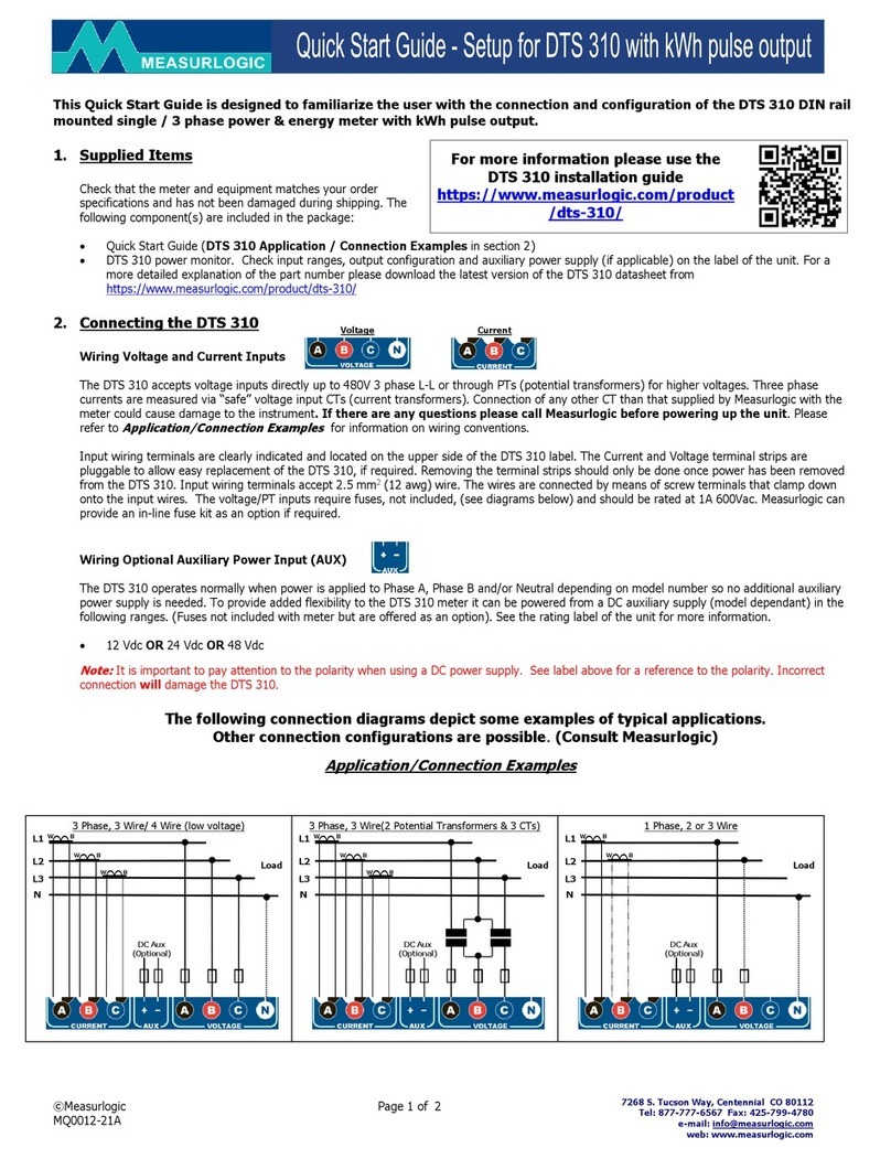
3 Phase, 3 Wire/ 4 Wire (low voltage)
L1
N
L2
L3
Load
DC Aux
(Optional)
W
B
W
B
W
B
L1
N
L2
L3
Load
DC Aux
(Optional)
W
B
W
B
W
B
3 Phase, 3 Wire (2 Potential Transformers & 3 CTs)
L1
N
L2
L3
Load
DC Aux
(Optional)
W
B
W
B
1 Phase, 2 or 3 Wire

©Measurlogic Page 3 of 6
MQ0012-22A
7268 S. Tucson Way, Centennial CO 80112
Tel: 877-777-6567 Fax: 425-799-4780
web: www.measurlogic.com
Wiring the Digital Pulse Output
The DTS 310 serial meter has 2 x Digital Inputs and 1 x Digital Output.
Digital Inputs (Marked 1, 2)
•Digital Counter Inputs, which interface to an external NO (Normally Open) dry contact switch.
Digital Output (Marked 3)
•The digital output is a potential-free NO (Normally Open) solid state relay output.
•The maximum switching voltage is 50Vdc and the maximum switching current is 100mA.
•The relay closure pulse width is 100ms. This minimum time between any two pulses is 100ms.
•The default pulse rate is 1 pulse per kWh. This can be changed using DTS Config.
Switch Settings for the Current Sensor Type and Sensitivity
The DTS 310 energy serial meter has an 8-way DIP switch situated next to the pluggable 6-way I/O terminal. [SW.1..SW.3] are is used to
configure current sensor type and sensitivity (Highlighted in BLUE in diagram below). The CT Rating must be set using DTS Config.
ATTENTION –SWITCHES [SW.1..SW.3]
•The DTS 310 will be shipped with all the CT Type switches in the “OFF”position.
•The DTS 310 switches MUST be setup by the user to match the CT Type.
•The DTS 310 CT Rating current MUST be set using DTS Config.
The DTS 310-3x-SB-A-x meter is compatible with the following current sensors:
•333mV Output CTs –This type of current sensors is internally burdened so that the voltage output is 333mV for the current rating that
is specified on the CT itself. The current rating of the CT must be specified when ordering and cannot be changed in the field. The
switches [SW.1..SW.3] on the DTS meter must be set for “333mV CT” (all OFF). The CT Rating cannot be set using the switches
and MUST be set using DTS Config.
•Rogowski Coil CTs –This is a flexible CT. The sensitivity of this type of current sensor is specified in milli-volts (mV) per 1000A at
60Hz. Different models of Rogowski Coils have different sensitivities, which must be selected from the tables and the switches
[SW.1..SW.3] set accordingly. The CT Rating that is set using DTS Config does not affect the current measurement values. We
recommend that you set the CT Rating in DTS Config to the panel rating, or the expected nominal current being measured.
ATTENTION
If multiple CTs per phase are required, please consult our document
“Using Multiple CT Sets with DTS Meters” in the “Technical” section of the DTS 310 webpage
at https://www.measurlogic.com/product/dts-310/
“1” & “2”
Digital Counter
Inputs

©Measurlogic Page 4 of 6
MQ0012-22A
7268 S. Tucson Way, Centennial CO 80112
Tel: 877-777-6567 Fax: 425-799-4780
web: www.measurlogic.com
Switch Label Lookup Examples
Corresponding Switch Settings
Standard 333mV CT
Current Rating of CT is set using DTS Config
Rogowski Coil
140mV per 1000A @ 60Hz
Nominal Current is set using DTS Config
The Maximum Current
for this Rogowski Coil is
2500A
Rogowski Coil
70mV per 1000A @ 60Hz
Nominal Current is set using DTS Config
The Maximum Current
for this Rogowski Coil is
5000A

©Measurlogic Page 5 of 6
MQ0012-22A
7268 S. Tucson Way, Centennial CO 80112
Tel: 877-777-6567 Fax: 425-799-4780
web: www.measurlogic.com
Communications Parameters –Selected using the Switch Settings
The DTS 310 energy serial meter has an 8-way DIP switch situated next to the pluggable 6-way I/O terminal. SW.4 is used to select between
Modbus RTU and BACnet MS/TP protocols. [SW.5..SW.8] is used to select the device address (Highlighted in PURPLE in the diagram below).
ATTENTION –SWITCHES [SW.4..SW.8]
•The DTS 310 will be shipped with all comms switches in the “OFF”position.
•The default setting is Modbus RTU, 9600 baud, address 100.
The DTS 310-3x-SB-A-x meter communication group of switches is sub-divided as follows:
•Serial Protocol –The serial protocol is selected using SW.4, where the OFF position is Modbus RTU and the ON position is
BACnet MS/TP. The protocol is always determined by this SW.4 even for the custom configuration.
oThe baud rate for Modbus RTU when using the switch options is 9600.
oThe baud rate for BACnet MS/TP when using the switch options is 38400.
•Device Address –As only 4 switch positions [SW.5..SW.8] are available, the choices of device addresses is tailored to be the most
suitable for the protocol selected:
(Please see the next section for custom communications settings.)
•Modbus RTU –All four switches in the OFF position is the Measurlogic default Modbus address of 100. The further Modbus Address
options are 101 through to 114 as shown in the table.
•BACnet MS/TP –All four switches in the OFF position is the generally accepted MAC address of 1 for new devices. It is
recommended that the MAC address is changed to another value during commissioning. Note that the further MAC address switch
options are 5 through 18 as shown in the table. The MAC address is automatically added to 473000 to generate the Device ID.
Communications Parameters –Custom Settings
If the switches [SW.5..SW.8] are all in their “ON” position, then “CUSTOM” communications parameters can be set for baud rate, address/MAC,
Device ID. The protocol is always determined by SW.4 even for the custom configuration. We recommend the following procedure:
Step
Description
Modbus RTU
BACnet MS/TP
1
Select the desired protocol, and set switches [SW.5..SW.8] all OFF
SW.4 is OFF
SW.4 is ON
2
Verify that the meter communicates at
Modbus 100 at 9600 baud
BACnet MAC 1 at 38400
3
Power OFF the meter
4
Set the switches [SW.5..SW.8] all ON
5
Power ON the meter
6
The meter will communicate with the same parameters as above
Modbus 100 at 9600 baud
BACnet MAC 1 at 38400
7
Change the communication parameters as desired
Use DTS Config
Use YABE
The custom communication parameters will be persistent and will be retained if power is lost to the meter.
After custom communications parameters are configured, DO NOT change [SW.4..SW.8].
Doing so, will revert to the communication parameters defined by the switches and the custom parameters will be lost.

©Measurlogic Page 6 of 6
MQ0012-22A
7268 S. Tucson Way, Centennial CO 80112
Tel: 877-777-6567 Fax: 425-799-4780
web: www.measurlogic.com
Switch Label Lookup Examples
Corresponding Switch Settings
Protocol Modbus RTU
Baud Rate 9600
Modbus Address 100
As shipped communications parameters
Protocol BACnet MS/TP
Baud Rate 38400
MAC Address 7
Device ID 473007
Protocol Modbus RTU
Baud Rate CUSTOM
Modbus Address CUSTOM
After custom communications parameters
are configured, DO NOT change [SW.4..SW.8].
This manual suits for next models
6
Table of contents
Other Measurlogic Measuring Instrument manuals

Measurlogic
Measurlogic DTS 307 User manual

Measurlogic
Measurlogic DTS SMX User manual

Measurlogic
Measurlogic DTS 310 User manual

Measurlogic
Measurlogic DTS 310 Guide

Measurlogic
Measurlogic DTS 310 User manual

Measurlogic
Measurlogic DTS 310 User manual

Measurlogic
Measurlogic DTS 307 User manual

Measurlogic
Measurlogic DTS DC User manual