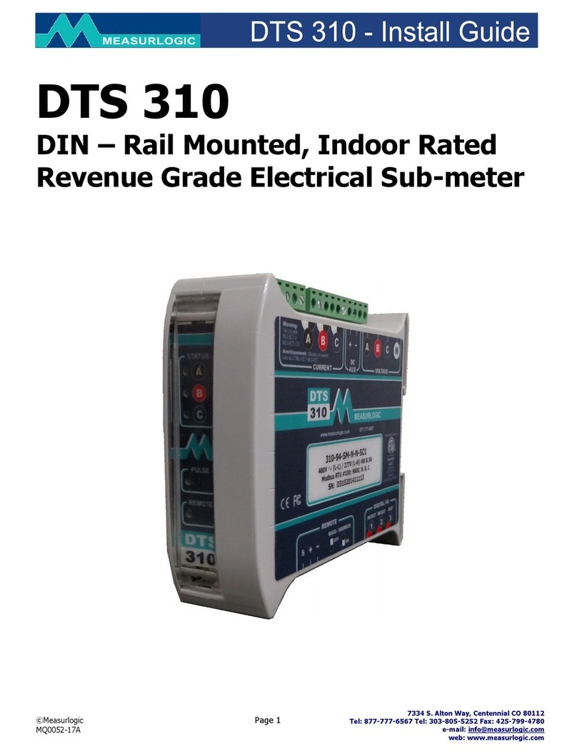
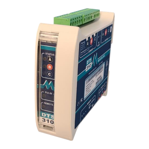
This Quick Start Guide is designed to familiarize the user with the connection and configuration of the DTS 310 DIN rail
mounted single / 3 phase power & energy meter with kWh pulse output.
1. Supplied Items
Check that the meter and equipment matches your order
specifications and has not been damaged during shipping. The
following component(s) are included in the package:
•Quick Start Guide (DTS 310 Application / Connection Examples in section 2)
•DTS 310 power monitor. Check input ranges, output configuration and auxiliary power supply (if applicable) on the label of the unit. For a
more detailed explanation of the part number please download the latest version of the DTS 310 datasheet from
https://www.measurlogic.com/product/dts-310/
2. Connecting the DTS 310
Wiring Voltage and Current Inputs
The DTS 310 accepts voltage inputs directly up to 480V 3 phase L-L or through PTs (potential transformers) for higher voltages. Three phase
currents are measured via “safe” voltage input CTs (current transformers). Connection of any other CT than that supplied by Measurlogic with the
meter could cause damage to the instrument. If there are any questions please call Measurlogic before powering up the unit. Please
refer to
Application/Connection Examples
for information on wiring conventions.
Input wiring terminals are clearly indicated and located on the upper side of the DTS 310 label. The Current and Voltage terminal strips are
pluggable to allow easy replacement of the DTS 310, if required. Removing the terminal strips should only be done once power has been removed
from the DTS 310. Input wiring terminals accept 2.5 mm2(12 awg) wire. The wires are connected by means of screw terminals that clamp down
onto the input wires. The voltage/PT inputs require fuses, not included, (see diagrams below) and should be rated at 1A 600Vac. Measurlogic can
provide an in-line fuse kit as an option if required.
Wiring Optional Auxiliary Power Input (AUX)
The DTS 310 operates normally when power is applied to Phase A, Phase B and/or Neutral depending on model number so no additional auxiliary
power supply is needed. To provide added flexibility to the DTS 310 meter it can be powered from a DC auxiliary supply (model dependant) in the
following ranges. (Fuses not included with meter but are offered as an option). See the rating label of the unit for more information.
•12 Vdc OR 24 Vdc OR 48 Vdc
Note:
It is important to pay attention to the polarity when using a DC power supply. See label above for a reference to the polarity. Incorrect
connection will damage the DTS 310.
The following connection diagrams depict some examples of typical applications.
Other connection configurations are possible. (Consult Measurlogic)
Application/Connection Examples
