Mebay GSCloud DT1000 User manual

DT1000 GSCloud®Monitoring Communication Module User Manual
1
DT1000 GSCloud Monitoring Communication Module
User Manual

DT1000 GSCloud®Monitoring Communication Module User Manual
2
Software Version
No.
Version
Date
Note
1
V1.0
2020-09-1
Original release.
Chongqing Mebay Technology Co.,Ltd
Add: No6-2,Building 4, Gangan Rd, Jiangbei District, Chongqing.
Tel:+86-23-6869 3061
Fax:+86-23-6765 8207
Web:http://www.mebay.cn
http://www.cqmb.cn
E_mail:[email protected]

DT1000 GSCloud®Monitoring Communication Module User Manual
3
Symbol Description
Symbol
Description
Note
Remind operators to operate correctly, otherwise it may cause
the equipment not to work correctly.
Be care
It is indicated that potential hazards can damage equipment
without proper precautions.
Warning
It is indicated if appropriate preventive measures are not taken,
potentially dangerous situations may result in death, serious
personal injury or significant property losses.

DT1000 GSCloud®Monitoring Communication Module User Manual
4
Warning
1. The installation of this equipment must be carried out by professionals.
2. When installing and operating the controller, please read the entire instruction
manual first.
3. Any maintenance and commissioning of the equipment must be familiar with all the
equipment
Be Care
1. Please keep the good connection of the power supply of the controller. Do not
share the connection lines of the positive and negative electrodes of the battery
with the floating charger.
2. During the operation of the engine, do not disconnect the battery, otherwise it may
cause damage to the controller.

DT1000 GSCloud®Monitoring Communication Module User Manual
5
Catalogue
Summary................................................................................................................................... 6
Main Features........................................................................................................................... 6
Parameters................................................................................................................................6
Overall Dimension and Wiring Diagram............................................................................... 7
Installation instruction.............................................................................................................. 8
Panel and display Instruction................................................................................................. 9
Operation.................................................................................................................................10
Parameter list......................................................................................................................... 12
Fault Finding........................................................................................................................... 14
Notes:
1. All rights reserved. No part of this duplication may be reproduced in any material
form (including photocopying or storing in any medium by electronic means or others)
without the written permission of the copyright holder.
2. MEBAY Technology reserves the rights to change the contents of this document
without prior notice.

DT1000 GSCloud®Monitoring Communication Module User Manual
6
Summary
DT1000 is the data acquisition and communication module of GSCloud®
generator set cloud control system developed by our company, which is WIFI/ET
version. Its main function is to connect the generator set controller to the
interconnection network, to realize the computer PC terminal and mobile phone APP
remote real-time monitoring generator set, to realize the remote control unit, remote
data monitoring, remote fault diagnosis, unit position real-time positioning,
maintenance management and so on.
It has RS485 communication port, which can read and write the commonly
controlled data. The internal integration of GPS module can realize the positioning of
the unit. The communication module adopts European lock terminal, the connection
is firm and the installation is convenient.
Main Features
DT1000:Support WIFI/ET network,GPS, with RS485 and other functions;
It can be connected to cloud server through WIFI wireless network or Ethernet
interface, and one communication module can monitor one generator set;
Using ARM kernel 32bit single chip microcomputer, processing speed, strong
expansion ability.
Wide range of working power supply DC (8 ≤ 36) V.
With USB-B interface, DTU parameters can be set through the PC;
It has good extended function, extensible environment detection, other equipment
parameter detection and other modules.
Data communication protocol using encryption algorithm.
a compression algorithm is adopted to greatly reduce the flow consumption.
the module is provided with the GPS positioning and the base station positioning
function, and the real-time positioning of the unit can be realized.
with two sets of programmable switch quantity input ports.
When the generator set alarm, can immediately upload data to the server.
the working state of the module is indicated by the LED indicating lamp, and the
working state of the module is conveniently realized by the user in real time.
The installation or screw fixation of the standard type 35mm guide rail is adopted.
Modular structure design, ABS shell, light weight, compact structure, easy to install.
Parameters
Options
Parameters
Working voltage
DC8V----36V Continuous
Power consumption
Standby:24V:MAX 1W
Working:24V:MAX 5W
USB Device
Type B USB port
RS485
Isolated
WIFI
SMA Port antenna and support 802.11b/g/n standard
GPS
SMA port

DT1000 GSCloud®Monitoring Communication Module User Manual
7
ETHERNET
RJ45 10/100Mbps self-adaption network interface
Switch value input 1
Available if connecting with Battery -
Switch value input 2
Available if connecting with Battery -
Working condition
-25-65℃
Storage condition
-40-85℃
Overall dimension
106.5mm*74mm*31mm
Weight
0.15Kg
Overall Dimension and Wiring Diagram
Overall Dimension:
74 31
74
31
106.5
35
DT1000 GSCloud®Monitoring Communication Module User Manual
8
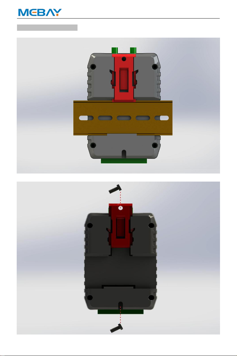
Installation instruction
35mm guideway installation:
Screw (M4) installation:
DT1000 GSCloud®Monitoring Communication Module User Manual
9
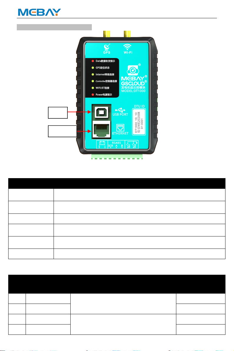
Panel and display Instruction
Panel instruction
Indicator name
Main function
Data
DTU sends data in red for LED lights and green for LED lights when
receiving data.
GPS
The GPS module successfully obtains the positioning information and
lights it up.
Internet
Lights up after a successful connection to the Internet network.
Controller
When the DTU is successfully connected to the controller, the LED
lights up.
WIFI/ET
When the DTU connects to the WIFI/ET successfully, the LED lights
up.
Power
After the module is turned on, the LED lights up.
Port description:
No.
Function
Description
Cable cross
sectional area
1
Power +
DC8V to 36V continuous power supply
1.0mm2
2
Power -
1.0mm2
3
RS485-SCR
RS485 port
0.5mm2
4
RS485-A
0.5mm2
Ethernet
USB-B
DT1000 GSCloud®Monitoring Communication Module User Manual
10
5
RS485-B
0.5mm2
6
Aux. Input 1
Ground connected is active (B-).
0.5mm2
7
Aux. Input 2
Ground connected is active (B-).
0.5mm2
8
USB Device
Type B USB port
9
Ethernet RJ45
RJ45 interface network cable
Operation
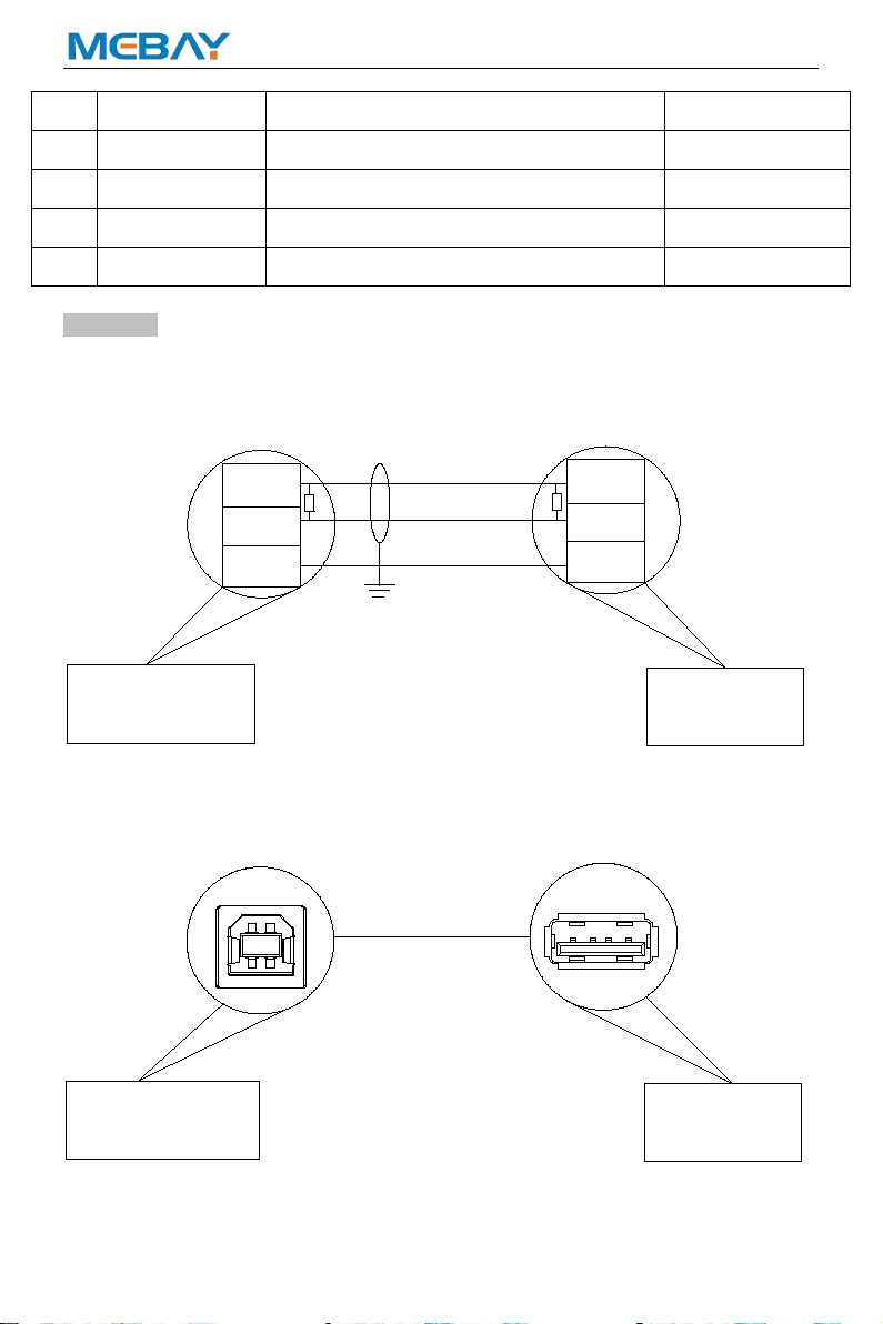
Communication and port functions:
RS485 port:Connect to the RS485 port of the generator controller through the
RS485 port:
A
BB
A
RS485
120Ω
120Ω
SCR SCR
Diesel Genset
Controller DT4000
USB Device:USB port and PC USB port connection, can be parameter settings,
module ID and registration password.
USB
PC
DT4000
DT1000 GSCloud®Monitoring Communication Module User Manual
11
WIFI port :Connect the WIFI IPX antenna to the Antenna port (50Ω/SMA female socket); Support 802.11b/g/n standard.
ETHERNET RJ45: Connect the network cable to the RJ45 network interface.
GPS port:When using GPS positioning function, GPS antenna is connected to DTU module,
antenna port: 50 Ω / SMA master, active antenna.
Note: GPS antenna needs to be placed outside the open, otherwise the position information is inaccurate or can not get the
position information.
Note: The GPS antenna and the WIFI antenna cannot be reversed.
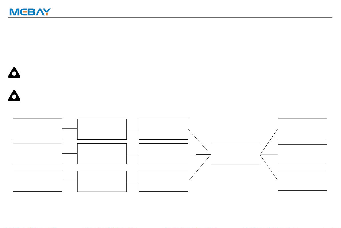
System application diagram
DT1000
Diesel Genset
Controller
Cloud server
Cell Phone
PAD
PC
Router
Router
Router
Diesel Genset
Controller
Diesel Genset
Controller
DT1000
DT1000
DT1000 GSCloud®Monitoring Communication Module User Manual
12
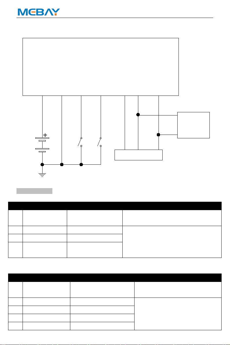
Typical Wiring Diagram
DC8-36V
A B
Extend
Module
+-IN1 IN2 A B
DT1000
RS485
SCR
SCR
Parameter list.
1. GPS
No
Parameter
Range (default)
Notes
1
GPS functional
enable
0-1(1)
0:manual input;
1:GPS module acquisition position
2
Set Longitude
-180°-180° (0.00000)
Manual entry of communication module
GPS location, altitude
3
Set latitude
-90°-90° (0.00000)
4
above sea level
-9999.9-9999.9m
(100.0m)
2. WIFI/ET
No
Parameter
Range (default)
Notes
1
DHCP Enable
0-1 (1)
0:Manual input;
1:Auto obtain IP address.
2
IP Address
0-255 (192.168.0.1)
All changes of Ethernet (like IP
address, Subnet address) are
active after module rebooting.
3
Subnet Mask
0-255 (255.255.255.0)
4
Default Gateway
0-255 (192.168.0.1)
5
DNS Address
0-255 (192.168.0.1)

DT1000 GSCloud®Monitoring Communication Module User Manual
13
6
SSID
(0-65535)
32 characters
7
Password
(0-65535)
64 characters
3. Switch input function setting
No
Parameter
Range (default)
Notes
1
Aux. Input 1
0-9(0
:
disable)
0:disable
1:Remote Control Inhibited
2:Access Alarm Input
3:Fire Alarm Input
4:Louver status input
5-9:Reserved
2
Aux. Input 2
0-9(0
:
disable)
4. Communication Settings
No
Parameter
Range (default)
Notes
1
485 baud rate
9600-38400(19200)
Baud rate of Communication between DTU
and Controller.
2
Running data
upload interval
10-170S(10)
The interval between uploading data to the
server while the generator is running.
3
Standby data
upload interval
90-170S(90)
The interval between uploading data to the
server while the generator is standby.
5. Model selection of generator controller
No
Parameter
Range (default)
Notes
1
MEBAY
DC20D MKII
DC4/5/6/7XD series
MEC20
DSE6120
HGM6120
HGM6110
DC18D
DC8/9XD series
Select the model of the generator
controller connected to the DTU. Can
match the DC4xDR series, DC5xDR
series, DC6xDR series and DC7xDR
series DC8XDR, DC9XDR generator
controller produced by MEBAY.
It also supports MEC20 Thomson series
and other types of controllers.
6. Extended module setting
No
Parameter
Range (default)
Notes
1
Temperature and
humidity module
0:Disable
1:Enable
Sets whether the temperature and humidity
detection module is enabled.
2
Alarm value for
excessive ambient
temperature.
0-80(40)
℃
When the ambient temperature is higher
than this setting value, upload the alarm
information with too high ambient
DT1000 GSCloud®Monitoring Communication Module User Manual
14
temperature, and disable this alarm when
set to the minimum value.
3
Alarm value of too
low ambient
temperature
-30-50(4)
℃
When the ambient temperature is lower
than this setting value, upload the alarm
information of the environment temperature
is too low, set to the maximum value to
disable this alarm.
4
Temperature,
humidity and CO
module.
0:Disable
1:Enable
Sets whether the temperature, humidity and
carbon monoxide concentration detection
module is enabled.
5
CO concentration
over high alarm
value
0-2000ppm
(250ppm)
When the carbon monoxide concentration
is higher than this setting value, upload the
carbon monoxide concentration alarm
information, set to the maximum value to
disable this alarm.
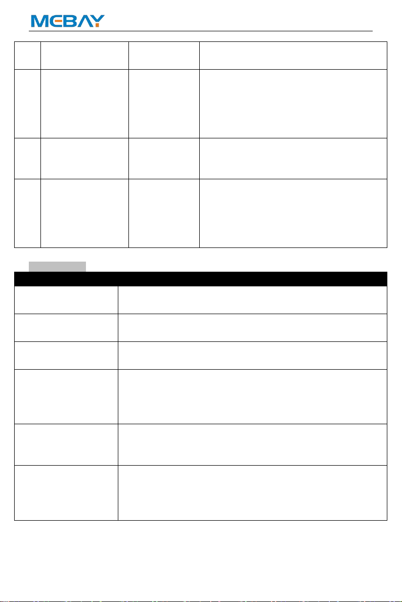
Fault Finding
Symptoms
Possible Solutions
Controller no response
with power.
Check power voltage.
Check controller connection wiring.
All LED lights are on.
Check network cable to the RJ45 network interface.
Check if the WIFI IPX antenna is connected to the antenna port.
Network LED
not light up
Check whether the Ethernet parameter settings are normal.
Check whether the network cable is normal.
GPS Not Gained
Location
Check GPS parameters are enabled or not.
Check GPS antenna is connected or not and placed outdoor or
not.
Check that the GPS antenna is placed outside the open room.
RS485
Communication
Abnormal
Check connections
Check settings of genset ID and baud rate are correct or not.
Check that A and B of RS485 are reversed.
USB Port
Communication
Abnormal
Check connections
Check whether the USB port of the computer is normal
Check whether the driver is installed normally
Check that the controller is properly energized
Popular Conference System manuals by other brands

Scientific Atlanta
Scientific Atlanta Explorer 2100 User's installation guide

Becker
Becker REU6100 Installation and operation

Mitel
Mitel SX-200 user guide

RELACART
RELACART CS-200 operating instructions

BMW Motorrad
BMW Motorrad Fit-for-All operating instructions

Aethra
Aethra THESEUS User and installation manual

Polycom
Polycom RealPresence Group Series Administrator's guide

Yealink
Yealink MVC400 quick start

Polycom
Polycom CX7000 series Administrator's guide

Polycom
Polycom VSX 3000 Administrator's guide

DataComm Electronics
DataComm Electronics Home Command Center II Instruction/installation sheet

AVIRE
AVIRE DCP quick start guide


