Mecc Alte ECO-ECP 4 Manual

SELF-REGULATINGALTERNATORSSERIESECO-ECP
OPERATINGANDMAINTENANCEINSTRUCTIONS
ALTERNATORIAUTOREGOLATISERIEECO-ECP
ISTRUZIONI PER L’USO E LA MANUTENZIONE
ALTERNATEURSAUTO-REGULESSERIEECO-ECP
MANUEL D’INSTRUCTION ET DE MAINTENANCE
SELBSTREGELNDERGENERATORSERIEECO-ECP
BETRIEBS-UNDWARTUNGSANLEITUNG
ALTERNADORESAUTOREGULADOSSERIEECO-ECP
INSTRUCCIONESPARAUSOYMANTENIMIENTO
自调节式发电机 ECO-ECP系列
操作及保养手册
САМОРЕГУЛИРУЕМАЯ ГЕНЕРАТОРЫ СЕРИИ ECO-ECP
ЭКСПЛУАТАЦИЯ И ТЕХНИЧЕСКОЕ ОБСЛУЖИВАНИЕ ИНСТРУКЦИЯ
SAMOREGULAČNÍ ALTERN SERIES ECO-ECP
OPERACEAÚDRŽBU
ÖNSZABÁLYOZÓGENERÁTORSERIESECO-ECP
ÜZEMELTETÉSIÉSKARBANTARTÁSIUTASÍTÁSOK
SAMOREGULUJĄCY SERIES ALTERNATORY ECO-ECP
OPERACJEIKONSERWACJI
AUTOREGLAREALTERNATOARESERIAECO-ECP
OPERAȚIUNIINSTRUCȚIUNILORDEÎNTREȚINEREȘI
SAMOREGULAČNÉ ALTERNA SERIES ECO-ECP
OPERÁCIEAÚDRŽBU
ECO-ECP
GB
IT
F
D
E
CN
SK
RO
RU
CZ
HU
PL
2ECO-ECP iMANUAL December 2013 Rev. 03
ECO - ECP MANUAL ENGLISH
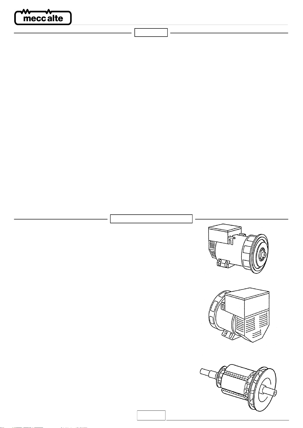
ECO-ECP 2 and 4 pole alternators are brushless, self-regulating and
incorporate a rotating inductor with damper cage winding and a fixed stator
with skewed slots.
The stator windings have a shortened pitch to reduce the harmonic content
of the output waveform.
The alternators are made in compliance with the 2006/42, 2006/95, 2004/108
CEE directives and their amendments, and the CEI 2-3, EN 60034-1, IEC 34-
1, VDE 0530, BS4999-5000, CAN/CSA-C22.2 N°14 -N°100 regulations.
Tests to verify the electromagnetic compability have been carried out in the
foreseen conditions by the standards with the neutral connected to the earth.
On customer’s request alternators can be manufactured according to
different specifications.
The robust mechanical construction gives good access to the generator
output connections, and allows the user to inspect the various components
with ease.
The casing is made of steel, the shields of cast iron, and the shaft of C45
steel and it has a keyed fan.
The mechanical protection level meets standard IP21 (upon request higher
levels of protection can be supplied).
Insulation materials meet Class H requirements, and all rotating components
are epossy resins impregnated; higher voltage parts, such as the stators, are
vacuum-treated (special treatments are available on request).
MACHINE DESCRIPTION
INDEX
MACHINE DESCRIPTION ....................................................................................................... pag. 2
INTRODUCTION ...................................................................................................................... pag. 3
MACHINE IDENTIFICATION ................................................................................................... pag. 3
INSPECTION ON DELIVERY .................................................................................................. pag. 3
SAFETY REQUIREMENTS ..................................................................................................... pag. 3
TRANSPORT AND STORAGE ................................................................................................ pag. 8
MECHANICAL COUPLING ..................................................................................................... pag. 9
ELECTRICAL CONNECTIONS ............................................................................................. pag. 12
STARTING AND STOPPING OPERATIONS ........................................................................ pag. 16
CLEANING AND LUBRIFICATION ....................................................................................... pag. 16
MAINTENANCE ..................................................................................................................... pag. 16
DEFECTS AND REMEDIES .................................................................................................. pag. 26
SPARE PARTS ...................................................................................................................... pag. 27
TABLES ................................................................................................................................. pag. 30
OVERALL DIMENSIONS ...................................................................................................... pag. 46
DSR APPENDIX .................................................................................................................... pag. 52
DER1 APPENDIX .................................................................................................................. pag. 56

3ECO-ECP iMANUAL December 2013 Rev. 03
ECO - ECP MANUAL ENGLISH
The ECO-ECP alternators comply with the EEC 2006/42, 2006/95,
2004/108 directives and their amendments; therefore they pose no
danger to the operator if they are installed, used and maintained
according to the instructions given by Mecc Alte and provided the
safety devices are kept in perfect working conditions.
Therefore a strict observance of these instructions is required.
Any reproduction of this manual is forbidden.
INTRODUCTION
Always indicate the generator type and code when contacting Mecc
Alte or the authorized after sales service centres.
MACHINE IDENTIFICATION
When the alternator is delivered, check that unit conforms with the
delivery note and ensure that there are no damaged or defective
parts; should there be any, please inform the forwarding agent, the
insurance company, the seller or Mecc Alte immediately.
INSPECTION ON DELIVERY
Before any cleaning, lubrication or maintenance operation, ensure that
the generator is stationary and disconnected from the power supply.
When stopping the generator, ensure the compliance with the proce-
dures for stopping the prime mover.
The generator, in fact, has no Emergency Stop, but is controlled by
the device arranged by the installer.
SAFETY REQUIREMENTS

4ECO-ECP iMANUAL December 2013 Rev. 03
ECO - ECP MANUAL ENGLISH
In consulting this use and maintenance manual, you will find several symbols, which have a specific meaning, as illustrated below.
CONVENTIONAL SYMBOLS AND SYMBOL DESCRIPTION
IMPORTANT
This symbol warns the personnel concerned that the described ope-
ration may cause damages to the machine if it is not carried out ac-
cording to the safety standards.
CAUTION
This symbol warns the personnel concerned that the described ope-
ration may cause damages to the machine and/or injures to the per-
sonnel if it is not carried out according to the safety standards.
WARNING
This symbol warns the personnel concerned that the described ope-
ration may cause serious injuries or death to the personnel if it is
not carried out according to the safety standards.
DANGER
This symbol warns the personnel concerned that the described ope-
ration may immediately cause serious injuries or death to the per-
sonnel if it is not carried out according to the safety standards.
IMPORTANT
SAFETY REQUIREMENTS

5ECO-ECP iMANUAL December 2013 Rev. 03
ECO - ECP MANUAL ENGLISH
HANDLER
This symbol identifies the type of operator in charge of the
operation described.
This qualification requires a complete knowledge and
understanding of the information contained in the manufacturer’s
instruction manual as well as specific skills about the hoisting
means, slinging methods and features and safe handling
procedures.
MECHANICAL SERVICE MAN
This symbol identifies the type of operator in charge of the
operation described.
This qualification requires a complete knowledge and
understanding of the information contained in the manufacturer’s
instruction manual as well as specific skills necessary to perform
installation, adjustment, maintenance, cleaning and/or repair
operations.
ELECTRICAL SERVICE MAN
This symbol identifies the type of operator in charge of the
operation described.
This qualification requires a complete knowledge and
understanding of the information contained in the manufacturer’s
instruction manual as well as specific skills necessary to perform
electrical operations such as connections, adjustment,
maintenance and/or repair.
The electrical service man must be able to work even in case
electrical cabinets and panels are live.
In case of exceptional operations and upon written request of
servicing operations please apply to Mecc Alte authorized centers.
SAFETY REQUIREMENTS

6ECO-ECP iMANUAL December 2013 Rev. 03
ECO - ECP MANUAL ENGLISH
Before installing the generator, arrangements must be made to
earth the machine.
This is the reason why you must make sure that the grounding sy-
stem is in good conditions and in compliance with the regulations of
the country where the generator will be installed.
CAUTION
THE FINAL INSTALLER IS RESPONSIBLE FOR THE INSTALLA-
TION OF ALL THE PROTECTIONS (SECTIONING DEVICES,
PROTECTIONS AGAINST DIRECT AND INDIRECT CONTACTS,
OVERCURRENT AND OVERVOLTAGE PROTECTIONS, EMER-
GENCY STOP, ETC.) NECESSARY FOR THE MACHINE TO
COMPLY WITH THE EXISTING INTERNATIONAL/EUROPEAN
SAFETY REGULATIONS.
For handling the unpacked generators, always use the special
eyebolts only; use ropes having a suitable carrying capacity and do
not lift the generator too much from the floor (max 30 cm.).
When the machine is worn cut, contact the companies in charge of
the disposal of ferrous material and do not throw away its parts into
the environment.
The operators in charge of the installation, operation and mainte-
nance of the generators must be skilled technicians who know the
characteristics of the generators.
The people in charge of the handling must always wear work gloves
and safety shoes. In case the generator or the whole plant must be
lifted from the floor, the operators must wear a safety helmet.
The generator must be installed in an airy room. If there is not
enough air, a malfunction or an overheating may occur (table 25
pag. 44). All entry doors into generator room should be clearly mar-
ked “Authorized persons only”.
Make sure that genset foundations and baseframe are suitable to
bear the combined weight of the alternators and prime mover.
The installer is responsible for the correct coupling of the generator
to the engine and for the performance of all precautions necessary
to guarantee the correct operation of the generator and avoid abnor-
mal stress, which could damage the generator (such as vibrations,
misalignment, strange noises or vibrations, etc.)
The machine was designed to guarantee the nominal power in envi-
ronments with a maximum temperature of 40° C, at altitudes lower
than 1000 m asl (EN60034-1), unless otherwise specified; for diffe-
rent operating conditions, see the commercial catalogue (brochure).
SAFETY REQUIREMENTS

7ECO-ECP iMANUAL December 2013 Rev. 03
ECO - ECP MANUAL ENGLISH
No person must wear fluttering clothes (such as scarves, etc.) near
the machine and any garment must be fastened with elastic bands at
its ends.
The generators must never and for no reason run whith following
guards removed:
-) terminals cover
-) front covers
-) fan guards.
During assembling and disassembling operations, hold carefully both
ends of the protection grid as the related material elasticity can be
harmful.
In some machines the regulators are equipped with 3 leds which can
be seen from the outside (as standard equipment on large machines,
as optional equipment on small machines):
Green led - correct operation
Yellow led - overload protection on
Red led - low speed protection on.
The generators are noisy (table 25 pag. 44); even if the sound level
is certainly lower than that of the prime motor, they must be installed
in soundproof rooms (room, engine room, etc.) where it is necessary
to wear antinoise protectors.
The generators produce heat proportional to the output.
Therefore, do not touch the generator if you do not wear antiscorch
gloves and, after switching it off, do not touch it until it has cooled
down.
Even if all the machine components are protected, keep away from
the machine.
Do not lean or sit on the generator for whatever reason.
Do not remove the labels for whatever reason; on the contrary, if
necessary, replace them.
DANGER OF SHORT CIRCUIT
The degree of protection of the generator is IP21; therefore it is
made prohibition to use whichever type of hydrocleaner and to spray
liquids over the parts containings electrical components.
In case of replacement of spare parts, use original spare parts only.
For the replacement of worn parts, carefully follow the maintenance
instructions; these operations must be carried out by skilled
technicians.
SAFETY REQUIREMENTS

8ECO-ECP iMANUAL December 2013 Rev. 03
ECO - ECP MANUAL ENGLISH
Alternators will be packed for shipment in a manner suitable to
their mode of transport and final destination.
Prior to handling goods, please ensure that lifting equipment is of
sufficient capacity. Under lifting conditions machinery should be
elevated to a minimal distance from the ground.
When lifting or moving goods by forklift apparatus, care should be
taken to ensure that forks are correctly positioned to prevent slip-
ping or falling of pallet or crate.
Both packed and unpacked alternators shall be stored in a cool
and dry room, and shall never be exposed to the inclemency of
the weather.
With regard to single bearing alternators (form MD35) please en-
sure that the rotor fixing clamps is in place. Failure to do so may
lead to slippage or assembly.
When installing the alternators, always lift them by using their
eyebolts (table 25 pag 44).
IMPORTANT :
AFTER PROLONGER STORAGE OR IF THE MACHINES
SHOW SIGNS OF CONDENSATION, ALL WINDINGS
SHOULD BE SUBJECTED TO INSULATION TESTS PRIOR
TO OPERATING.
THE INSULATION TEST SHALL BE MADE BY SKILLED PER-
SONNEL.
BEFORE CARRYING OUT THE TEST, THE VOLTAGE REGU-
LATOR MUST BE DISCONNECTED; IF THE TEST RESULTS
ARE TOO LOW (LOWER THAN 1 MΩ)(EN60204-1) THE AL-
TERNATOR MUST BE DRIED IN AN OVEN AT 50-60°C.
TRANSPORT AND STORAGE

9ECO-ECP iMANUAL December 2013 Rev. 03
ECO - ECP MANUAL ENGLISH
Once the generator is coupled with an engine, mounted on a ba-
seframe, or installed on a complete generating set, it cannot be
lifted by its lifting bolts. The relevant instructions for lifting comple-
te generating set should be followed.
Any packing materials should be disposed of via correct waste
disposal methods. Do not discard waste materials into the envi-
ronment.
MECHANICAL COUPLING
The mechanical coupling is under the sole responsibility of the fi-
nal user, and has to be done at his discretion (for tightening torque
see tab. 24 pag. 43).
A bad alignment may cause vibrations and bearing damages. It is
advisable to verify the compatibility of the engine / generator tor-
sional characteristics (by the customer).
The necessary data for this verification are available on the con-
cerning documentation.
Warnings:
BEFORE STARTING THE ALTERNATOR, CHECK THAT THE
AIR INLETS AND OUTLETS ARE FREE OF ANY OBSTRUC-
TIONS.
THE AIR INLETS SHOULD NOT BE NEAR ANY HEATING
SOURCES. IN ANY CASE, IF NOT SPECIFICALLY REQUE-
STED, THE COOLING AIR TEMPERATURE MUST BE EQUAL
TO THE ENVIRONMENT TEMPERATURE AND NEVER HIGHER
THAN 40°C.
DURING ASSEMBLING AND DISASSEMBLING OPERATIONS,
HOLD CAREFULLY BOTH ENDS OF THE PROTECTION GRID
AS THE RELATED MATERIAL ELASTICITY CAN BE HARMFUL.
BEFORE MECHANICAL COUPLING OF SINGLE BEARING
ALTERNATORS, REMOVE THE ROTOR SECURING DEVICE,
IF FITTED, PLACED THERE TO PREVENT ROTOR FROM
SLIPPING.
For transit and storage purposes the generator flange spigot and
the generator end shaft (for the generators in B3-B14 construction
form) have been coated with a rust preventer that can be remo-
ved easily.
This MUST BE removed before assemblying to the engine.
TRANSPORT AND STORAGE

10 ECO-ECP iMANUAL December 2013 Rev. 03
ECO - ECP MANUAL ENGLISH
A bad alignment may cause vibrations and bearing damages. It is advisable
to verify the compatibility of the engine / generator torsional characteristics
(by the customer).
The necessary data for this verification are available on the concerning docu-
mentation.
For the coupling of a generator with MD35 form, proceed as follows:
a) according to the type of the coupling, verify the correct placement of the
discs (dimension “L”) (table 24 pag. 43); if necessary restore the “L” dimen-
sion moving gently and axially the rotor. In the right position the clearance
of rear bearing should be from 0.5 to 2 mm.
b) (For series 28) through one of the two lateral openings, and by manually
rotating the rotor, detect the relevant clamp screw on the fan hub
c) (For series 28) let the fan be free to rotate by slackening the M8 screw by
means of an hexagonal wrench, possibly having an articulated head
d) (For series 28) position one of the disk holes near the upper part of one
of the side openings and place the slit that is on one of the fan blades, in
the same position
e) move the generator close to the coupling engine
f) align one of the flywheel disk fastening holes with the holes of the pre-
viously positioned disks (point “d”)
INSTRUCTIONS FOR THE ASSEMBLING OF GENERATORS WITH MD35 FORM MECHANICAL COUPLING

11 ECO-ECP iMANUAL December 2013 Rev. 03
ECO - ECP MANUAL ENGLISH
g) Insert and partially tighten the screws that lock the disks to the
flywheel. Keeping the fan still (ECP28), turn the flywheel until another
two holes are in the same position and partially tighten the screw.
Repeat this operation for all the other holes
h) after inspecting the correct centring of the disks on the engine
flywheel, the screws must be completely tightened
i) (For series 28) once the clamping of the disks is over, stop the fan
once again by tightening the screw with a torque wrench setting
adjusted at 20 Nm ± 10%; the radial position of the fan is not binding
for the correct operation of the system
l) fix the protection grids supplied with the generator.
Compliance with items "i" and "l" is of the utmost consequence in order
to avoid serious damages to the generator or hazardous situations for
people or objects.
Only after a correct mechanical coupling, proceed with the electrical
connections
MECHANICAL COUPLING

12 ECO-ECP iMANUAL December 2013 Rev. 03
ECO - ECP MANUAL ENGLISH
ELECTRICAL CONNECTIONS
All electrical output connections are the responsibility of, and are
at the discretion of, the end user.
When making terminal box connections, all cable and terminal lugs
should meet the relevant standards of the country of final destina-
tion.
WINDINGS CONNECTION
All alternators feature both star with neutral (Y) and delta (Δ) con-
nections (table. 2 pag.31).
To reconnect from a star to delta connection (for ex. from 400V to
230V), modify the linking arrangements on the output terminal
board (see diagram on table 2 page 31).
It is not necessary to adjust the voltage regulator.
Standard alternators are equipped with 12 cables to offer different
voltages (ex.230 / 400 / 460 / 800V).
The alternator must always be earthed by sufficiently rated cable,
using one of the inside or outside terminals. For the electrical con-
nections use wires suitable for the power of the generator and con-
nect them to the terminal board as indicated on table 12 or 17.
After completing output connections (for tightening torque see tab.
24 pag. 43), ensure that the terminal box cover is securely in pla-
ce.
IMPORTANT: frequency variations.
A standard production machine wound for 50 Hz can also function
at 60 Hz (and vice versa) by resetting the A.V.R. voltage potentio-
meter to the new nominal voltage value. When changing from 50
to 60 Hz the alternator power, and nominal voltage will increase by
20%, but the current does not change from 50 Hz value. Should
voltage stay at 50 Hz nominal value, then the output power may be
increased by 5% due to improved ventilation.
For machines wound for 60 Hz, changing to 50 Hz, the voltage
and power values have to decrease by 20% of 60 Hz value.
REGULATORS (table 3 pag 31)
Either U.V.R.6/1-F and S.R.7/2-G regulators can be used on the
ECO-ECP series without affecting performances.
The U.V.R.6/1-F is a standard feature on the 38 - 40 - 43 - 46 mo-
dels whereas the S.R.7/2-G is standard on the 28 - 31 - 32 - 34
series.
The two regulators ensure the same level of performance but have
different signal systems and references.

13 ECO-ECP iMANUAL December 2013 Rev. 03
ECO - ECP MANUAL ENGLISH
IMPORTANT:
the generator output voltage must be checked under no-load con-
ditions, with the correct setting of frequency.
The voltage may be adjusted by ± 5% of the nominal, by acting
upon the voltage potenziometer on the electronic regulators.
It is possible to get a remote voltage regulation of ± 5% inserting in
the proper terminals a 100K potentiometer (for the 6 lead units) or
a 100K potentiometer with a 100K resistance in series (for the 12
lead units)
Instructions to follow for the external potentiometer connection :
CAUTION: in order to get a correct working of the alternator, it is
necessary to follow the following procedure, connecting the exter-
nal potentiometer.
1) Turn the VOLT trimmer of the electronic regulator completely
anticlockwise.
2) Set the external potentiometer at half turn and connect it to the
proper terminals of the electronic regulator.
3) Adjust the voltage at the nominal value by the VOLT trimmer of
the electronic regulator.
PROTECTIONS
U.V.R.6/1-F - S.R.7/2-G
Both regulators are provided with an underspeed protection with
an intervention threshold which can be adjusted by the potentio-
meter marked “Hz”. This protection intervenes instantaneously by
reducing the alternator voltage to a safe value when frequency
falls below 10% of the nominal value. These regulators also have
inherent overload protection which senses the exciter field voltage
value. Should this field voltage value exceed the nominal value for
a period of more than 20 seconds, then again the alternator volta-
ge is automatically reduced to a safe operating level. This overload
function has a built-in delay to allow for the overload when starting
motors (normally 5-10 seconds). The operating threshold of this
protection device is adjustable by the potentiometer marked
“AMP”.
NOTE : When using the machine in single phase, or for voltages
different from the one pre-set at the factory, recalibration of the
AMP and STAB potentiometers could be necessary.
U.V.R.6/1-F
Aside from the above mentioned characteristics, the U.V.R.6/1-F
regulator also offers the following:
1 - possibility to have single-phase as well as three-phase sensing.
2 - led indicators for self-diagnosis which indicate the unit’s opera-
tional conditions: a green led which when lit confirms the alterna-
tor’s normal functioning; a red led indicates the underspeed protec-
tion is on; a yellow led indicates the overload protection is on.
ELECTRICAL CONNECTIONS

14 ECO-ECP iMANUAL December 2013 Rev. 03
ECO - ECP MANUAL ENGLISH
IMPORTANT
In normal functioning, only the green led has to be lit.
All these indicators can be remotely controlled and adjusted, for any type of
use, by utilizing the SPD96/A accessory which is available on request.
INTERVENTION OF PROTECTION DEVICES CAUSES.
Underspeed protection instantaneous intervention:
1 - speed reduced by 10% of nominal RPM.
Delayed intervention of overload protection:
2 - overload by 20% of nominal rating.
3 - power factor (cos φ) lower than the nominal-one.
4 - ambient temperature above 50°C.
Intervention of both protections:
5 - combination of factor 1 with factors 2, 3, 4.
In case of intervention the output voltage will drop down to a value which
will depend on the fault.
The voltage will return automatically to its nominal value as soon as the
fault is removed.
For further details on regulators, please see the specific manual.
OPTIONALS :
All ECO-ECP series alternators can function with manual regulation,
without assistance from any external source, by using a rheostat (tab. 10-
11 pag. 36).
ELECTRICAL CONNECTIONS

15 ECO-ECP iMANUAL December 2013 Rev. 03
ECO - ECP MANUAL ENGLISH
PARALLEL OPERATION
Should the alternators be required to operate in parallel, it is ne-
cessary to add a paralleling device to ensure equal droop of ge-
nerator output voltages.
This ensures that if the machines are operated separately, the
voltage droop (4% approx.) is equal when switching from no-load
to full load.
The parallel device is fitted as standard on 40 - 43 - 46 models,
therefore when two or more of these units must function in paral-
lel, it is sufficient to remove the bridge which shortcircuits the se-
condary winding of the parallel device.
On smaller models this device is mounted on request or it can be
added (except for ECP28/4) by the client himself following the in-
structions of tables 14-16-18-20.
After the device has been mounted, check whether the connec-
tion has been properly made; make sure that there is a voltage
drop of approximately 4% in the machines when they function in-
dividually switching at rated speed and cosφ0.8 from no-load to
full load operation.
HOW TO MOUNT THE PARALLEL DEVICE
Referring to tables 14-16-19 mount parallel device as indicated.
Connect the power turns in series with phase.
The numbers of turns to be wound on the transformer will be indi-
cated in the instruction accompanying the transformer itself.
The secondary winding of the parallel transformer must be con-
nected in series to the sensing of the electronic regulator as
shown on tables 4 - 5 page 32.
In order to activate the parallel device remove the bridge which
shortcircuits the secondary winding of the device itself as shown
in the above mentioned tables.
NOTE
When requesting a parallel device, it is necessary to indicate the
nominal data of the alternator on which the device will be applied.
After all the electric connections have been made and only after
all the protections have been put in place, can the system be
started.
ELECTRICAL CONNECTIONS

16 ECO-ECP iMANUAL December 2013 Rev. 03
ECO - ECP MANUAL ENGLISH
All the instrumentation for starting, running and stopping the sy-
stem shall be provided by the installer.
THE STARTING, RUNNING AND STOPPING OPERATIONS
MUST BE CARRIED OUT BY SKILLED PERSONNEL WHO HA-
VE READ AND UNDERSTOOD THE SAFETY INSTRUCTIONS
AT THE BEGINNING OF THIS MANUAL.
IMPORTANT :
When the system is set to work for the first time, which has to be
done at a reduced speed, the operator shall check that no anoma-
lous noises can be detected.
If an anomalous noise is detected, stop the system immediately
and improve the mechanical coupling.
CLEANING AND LUBRIFICATION
Prior to approaching or touching the alternator, ensure that it is
not live and it is at room temperature; at this stage it is possible to
clean it on the outside using compressed air.
NEVER USE LIQUIDS OR WATER.
DO NOT CLEAN THE INSIDE ELECTRIC COMPONENTS WITH
COMPRESSED AIR, BECAUSE THIS MAY CAUSE SHORT-
CIRCUITS OR OTHER ANOMALIES.
For the lubrication of bearings, see table 23 on page 42.
MAINTENANCE
The alternators series ECO-ECP are designed to give a long
maintenance free working life.
BEFORE PERFORMING THIS OPERATION, READ THE SAFE-
TY REQUIREMENTS AT THE BEGINNING OF THIS MANUAL
CAREFULLY.
Maintenance operations on Mecc Alte generators can be divided
into routine and extraordinary maintenance operations; in both
cases, all operations must be authorised by the safety represen-
tative and they must be carried out when the machine is turned
off and insulated from the electric installation or from the power
mains.
High qualified mechanical or electrical technicians must carry out
maintenance operations and any fault search since all operations
described hereunder could put personnel in serious danger.
It is also highly recommended to take all the necessary precau-
tions so as to prevent an inadvertent starting of the machine du-
ring maintenance and fault search operations..
STARTING AND STOPPING THE OPERATIONS

17 ECO-ECP iMANUAL December 2013 Rev. 03
ECO - ECP MANUAL ENGLISH
fig. a
fig. b
fig. c
MAINTENANCE
Routine maintenance operations can be summed up as follows:
a) Assessment of windings conditions after long periods of stora-
ge or inactivity
b) Assessment, on a regular basis, of correct functioning
(absence of anomalous noises or vibrations)
c) Mechanical inspections on all fastening bolts and, in particular,
on electric connections
d) external cleaning of generator
a) Assessment of windings conditions after long pe-
riods of storage or inactivity.
Measuring the insulating earth resistance can assess the condi-
tion of the windings. This measurement can be carried out with a
“Megger” device, or similar, with a 500V direct-current voltage. It
is very important to disconnect the voltage regulator (fig. a), the
rotating diode bridge (fig. b) and the radio-interference filter (fig.
c), as well as any other device connected to the windings to be
checked, before carrying out the measurement.
The figure resulting from the measurement of the windings’ earth
resistance must be over 1MΩ.
Should the figure be smaller than the above mentioned one, the
windings must be adequately dried up. This can be done by direc-
ting a jet of hot air of about 50-60°C into the generator’s air inlets
or outlets; alternatively, the stator’s windings can be electrically
connected and a voltage can be passed through them by means
of a directcurrent power supply. The amount of current in the win-
dings depends on the generator size, even though it must be fixed
according to the nominal values stated on the plate.
b) Assessment of current functioning (absence of ano-
malous noises or vibrations).
We recommend users to check regularly the correct functioning of
the generator, and to verify that there are no anomalous noises or
vibrations; their presence might indicate damage of bearings.
May we remind you that the alternator itself has no particular vi-
bration since the rotating parts are perfectly balanced. Provided
that the rotor balancing has not been altered and that the rotor’s
bearings have not been damaged, vibrations in the generator set
may occur due to alignments of couplings, due to stress upon the
combustion engine, or to vibration mounts.
We also recommend checking of performance data which must
comply with the data on the generator’s plate.

18 ECO-ECP iMANUAL December 2013 Rev. 03
ECO - ECP MANUAL ENGLISH
MAINTENANCE
c) Mechanical checks of fastening bolts and, in particu-
lar, of electric connections.
We recommend a regular check of all fastening bolts, which must
be perfectly tightened up. Special attention should be paid to all
electric connections; this inspection must be carried out in the com-
plete absence of voltage. To choose the correct tightening wren-
ches suitable for the different sizes of the bolts, see generator ma-
nual.
d) Internal and external cleaning of the generator.
For the external cleaning of the generator, you can use compres-
sed air. The use of hydrocleaners and detergent fluids is strictly
forbidden. The standard protection degree of the generator is
IP21; therefore, use of fluids could cause anomalies or even short-
circuits.
Extraordinary maintenance operations can be summed up as fol-
lows:
a) Maintenance and replacement (if necessary) of bearings
b) Cleaning of air filters (if available)
c) Cleaning of windings
d) Replacement of diode bridge
e) Replacement of exciter
f) Replacement of voltage regulator
g) Check of residual voltage
a) Maintenance and replacement (if necessary) of bearings.
During the assembling phase, all bearings are greased with SKF
LGMT2 grease, or similar.
All generators, except the ECO40, the ECO43N and ECO46 ver-
sions, are equipped with sealed bearings; for this kind of bearing, no
maintenance is required for the total operating time (estimated:
30.000 hours).
Bearings of alternator versions 40, 43 and 46 must be greased on a
regular basis by means of a pressure grease cup (see bearings
chart).
During the operating time, checks to detect presence of either ove-
rheating, or noises, must be carried out on a regular basis.
If the bearing is worn off, it can cause excessive vibrations. In such
a case, the bearing must be removed, examined, and if necessary,
replaced.

19 ECO-ECP iMANUAL December 2013 Rev. 03
ECO - ECP MANUAL ENGLISH
A description of the procedure for a bearing replacement.
Generator versions: 28-31-32-34.
To disassemble alternator versions 28-31-32-34, follow these in-
structions:
-) Remove front cover
-) Use a lifting device equipped with soft ropes of an adequate lif-
ting capacity to extract rotor. Make sure that the lifting devices are
suitable for the weight of the parts to be shifted
-) To pull the bearing out, use a puller
-) To insert new bearing, heat it with a suitable magnetic device
-) Put on safety gloves and insert bearing into its place
Generator versions: 38-40-43-46.
To disassemble alternator versions 38-40-43-46, remove exciter
as follows:
-) Remove rear seal
-) Disconnect the five wires of the rotating diode bridge “A” and
“B”.
MAINTENANCE

20 ECO-ECP iMANUAL December 2013 Rev. 03
ECO - ECP MANUAL ENGLISH
-) when dealing with versions 38, remove clamp screws from the dio-
des area of the rotating bridge, whilst when dealing with versions 40,
43 and 46, remove clamp bolt and, by pulling it gently, remove Diode
Bridge
-) insert an adequate puller to pull out exciter rotor
-) Pul out rotor from the drive end side; should the front lead diameter
be smaller than the impeller’s external diameter, remove lid to pull out
rotor
-) use a pair of suitable pliers to remove seeger rings
-) use a suitable puller to remove bearing
-) to insert new bearing, heat it with a suitable magnetic device
MAINTENANCE
This manual suits for next models
1
Table of contents
Languages:
Other Mecc Alte Inverter manuals


Popular Inverter manuals by other brands


Kaco
Kaco blueplanet 3.0 NX1 M2 manual

HP
HP 8642A operating manual

EFOY
EFOY Pro 12000 Duo Operation and installation manual

Srne
Srne HESP4860S100-H user manual

Perkins
Perkins 1106C Genset Systems operation testing and adjusting

Power One
Power One AURORA PVI-10.0/12.5-OUT-xx Operation and installation manual