LIVOLTEK Hyper 3-5kW User manual
Please prepare the cable before connecting as follows.
No.
1
2
3
4
Cable
AC cables
PV cables
Battery power cables
Cross Section Cable diameter (mm)
4mm - 6mm²
PE cable
²
4mm - 6mm² ²
4 AWG
12~10 AWG
•Do not work with power on. All
operations, cables and parts specification
during the electrical connection shall be in
compliance with local laws and regulations.
• Disconnect the DC switch of the inverter
to power off the inverter before any electrical
connections.
12~10 AWG
25mm ²
4mm - 6mm² ² 10 AWG
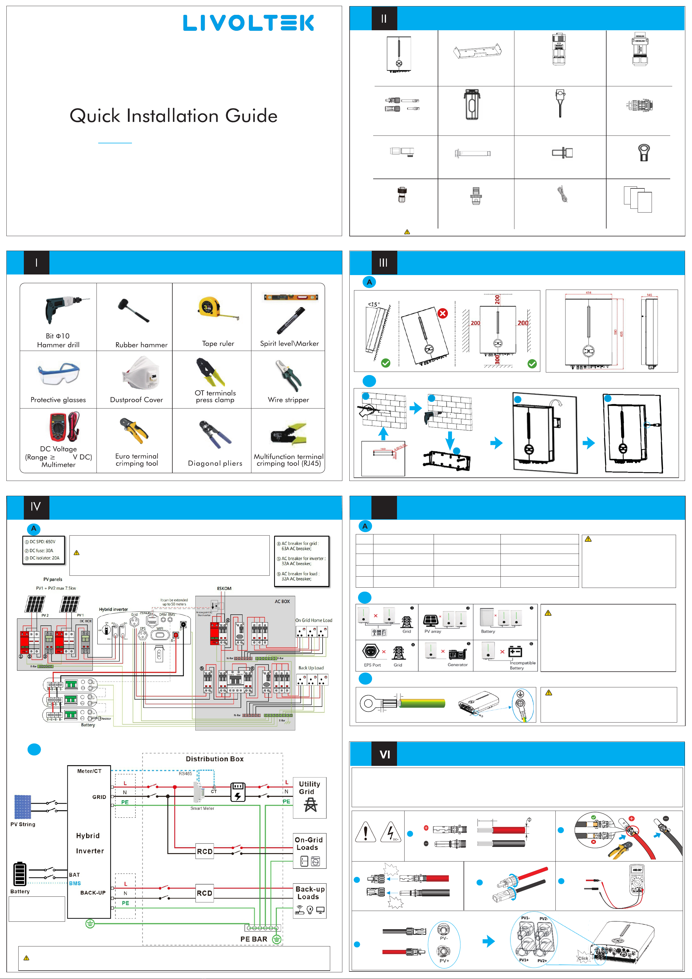
Unacceptable Installations
B
Notice:
Notice:
• Please avoid the following installations which will
damage the system or the Inverter.
• Any damage caused will not be covered by the warranty policy.
①M ulti inverters cannot be connected in parallel.
②S ingle PV string cannot be connected to multiple inverters.
③O ne battery bank cannot be connected to multiple inverters.
④T he EPS (backup) side cannot be connected to the grid.
⑤T he inverter cannot be connected to any AC generator directly.
⑥T he inverter cannot be connected to any incompatible batteries.
External Grounding (PE Cable) Connection
C
<2mm
<0~1.5 mm
• Ensure that the PE cable is securely connected.
Otherwise, electric shocks may occur.
• Do not connect the neutral wire to the enclosure as a PE cable.
Otherwise, electric shocks may occur.
Notice:
PV Cable Connection
Step 1 Remove an appropriate length of the insulation layer from the PV Strings power cables.
Step 2 Connect the red wire to the positive metal terminal, and the black to the negative and crimp them using a crimping tool.
Step 3 Insert the crimped positive and negative power cables into the corresponding connectors until a “click” sound is heard.
Step 4 Tighten the locking nuts on the positive and negative connectors.
Step 5 Measure the voltage of every route Strings using a multimeter. Ensure that the polarities of the DC input power cables are correct.
Step 6 Insert the positive and negative connectors into their corresponding terminals of the inverter until a click sound is heard.
PE Cable Connection
Notice:
•N and PE wiring via ON-GRID and BACK-UP ports of the inverter are differnet based on the regulation requirements of different regions.
•Refer to the speci fic requirements of local regulations.
•Ensure that the grounding of BACK-UP is correctly and tightened. Otherwise, the BACK-UP function may be abnormal in case of grid failure.
V
Positive metal terminals
Negative metal terminals
1
: 5.5~8mm
7~8mm
5
2
4
6
3
ClickClick
ClickClick
Hybrid Inverter(Hyper 3-5kW)
Inverter *1 Bracket *1
PV Connectors
*2 or 4 Wi-Fi Dongle *1 CT *1 Multi COM
connector *1
Battery power
Connectors *2 Expansion Bolts *4 Screws *1 PE terminal *1
BMS Connector *1
(for Li-Ion battery) DRM Connector *1 Battery Temp. sensor *1 Documents
EPS Connector *1 Grid
Connector *1
(Current Transformer)
(for Lead-acid battery)
Installation requirements
Wall mounting
B
111 2
3
45
The image shown here is for reference only. The actual product and quantity are based on delivery.
Notice:
600
Mounting
System Connection Diagram (Applies to most countries)
B
Electrical Connection Overview
This diagram indicates the wiring structure instead of the electric wiring standard of hybrid inverter.
1. For batteries with attached breaker, the external DC breaker could be omitted.
2. The recommended values in the table are for reference only.
3. The actual values must comply with local standard and actual conditions.
4. Only for lithium battery which has BMS communication.
5. Direction of the CT cannot be connected in reverse,
please follow "→Inverter" direction to do the connection
Notice:
Packing List
Preparation Tools
Wiring Diagram
If the battery is integrated
with a readily accessible
internal DC breaker, no
additional DC breaker
is required.
XII
IX
XI
XXI
XIIIXIII
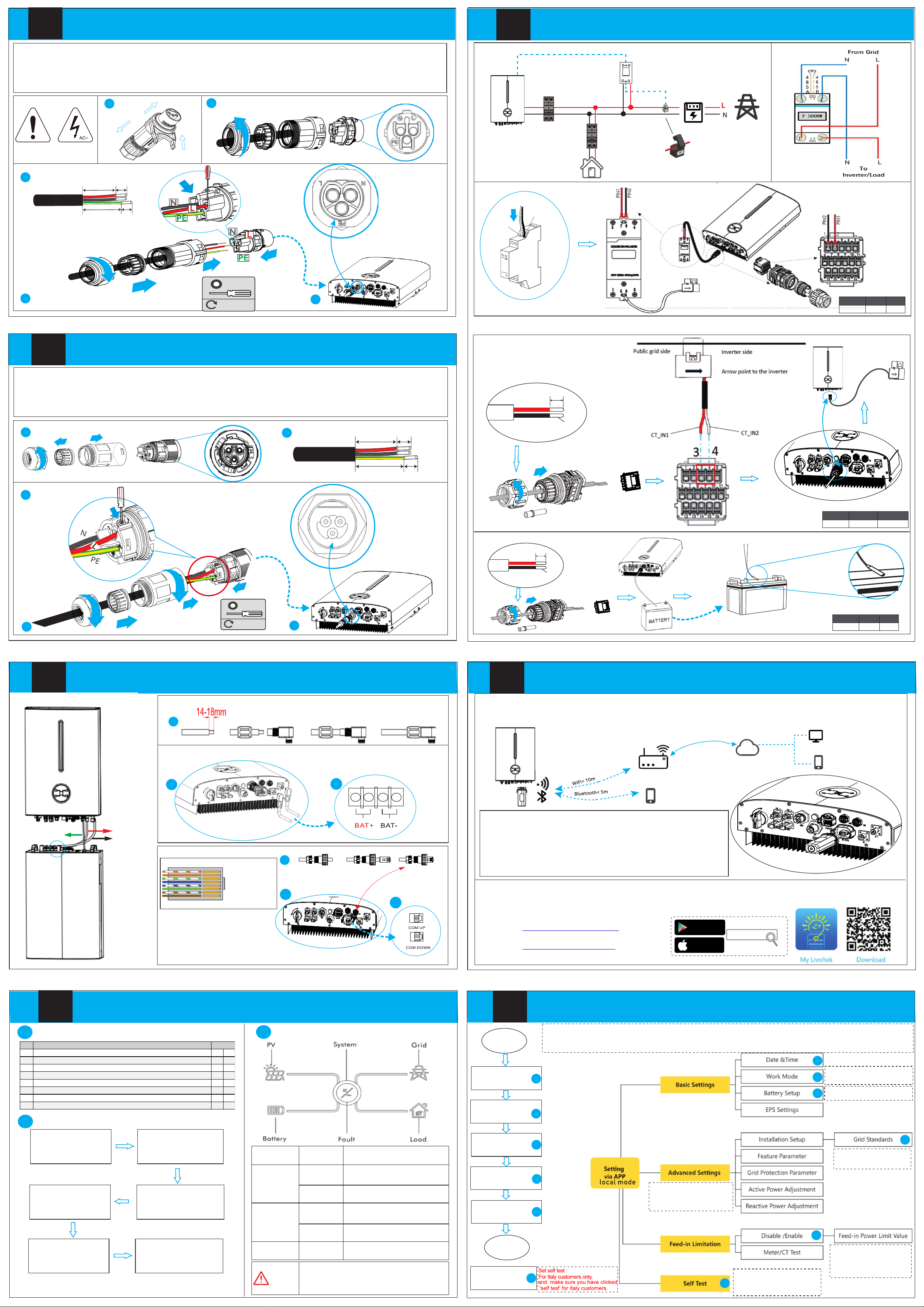
Wi-Fi Dongle Conne ction
COM(Meter/CT/NTC) Connection
Battery Connection
Start Guide
3
Communication
connection
Wi-Fi Dongle (Wi-Fi & Bluetooth 2in1 function) establish communication connection to the LIVOLTEK portal server
through wireless network to provide local or remote monitoring, data logging and maintenance on the inverter.
Server
‘My Livoltek' is a platform to communicate with your device via WiFi or bluetooth, you can login on our web(link as below) on your
computer, also you can scan the QR code to download the APP on your phone.
Wi-Fi Dongle Connection Steps:
Step 1 Remove the waterproof lid from the Wi-Fi/4G terminal.
Step 2 Insert the Wi-Fi Dongle into the communication port.
Step 3 Build the connection between the Wi-Fi dongle and home
WiFi router by our livoltek App local mode.
Refer the App guide manual delivered with the product or find it at our
App homepage 'guide' (please install 'My Livoltek' APP on your phone firstly)
Power ON/OFF the Inverter
Google Play
App Store
Mylivoltek
A Inspection before Commissioning
No. Content
1 All the switches connected to the inverter are set to the OFF position. Yes No
2 The inverter is installed correctly and securely.
3 All cables are connected correctly and securely.
4 Unused cable holes are fitted using the waterproof nuts.
5 The Wi-Fi Dongle is installed correctly and securely.
6 The electrical conduit holes are sealed.
7 The CT or smart meter is connected.
8 The battery is well connected.
State
Step 1
Turn on the AC breaker
on the ON-GRID side.
Step 2
Turn on the battery
breaker and Battery.
Step 3
Rotate the DC switch of
the inverter to ON position.
Step 6
Observe the
LED indicator.
Step 4
Turn on the AC breaker
on the BACK-UP side.
Step 5
Wi-Fi Dongle
connection.
Color Status Description
Green
Red
Green/Red
On
Off
On
Off
Blink
The inverter is running normally
Other statuses except Running
Fault occurs
No fault occurs
System startup or updating
B Powering on the System
C LED Display
Note: The shutdown steps are opposite to the above order.
XIII Initial Parameter Setting
WARNING
Before maintaining and commissioning inverter and its
peripheral distribution unit switch off all the charged
terminals of the inverter, and wait at least 10 minutes
after the inverter is powered off. .
Start
Set Date Time
Set the grid
standard
Set zero-export
Set work mode
Set Battery Value
Set Self test
End
1
2
1
1
1
1
3
4
5
1
66
14
1
2
1
5
To control the amount of power
injected in the grid.This function
requires the using of CT or
Smart Energy Meter. Otherwise,
this function will be unavailable.
Check or select the country
safety standards where the
inverter is installed.
1
1
Self-Define Mode
Self-Use Mode
Back-Up Mode
13
Select Battery Type ,
SOC Value
(Optional)
(Optional)
1
1
A: Battery power cables connection
Skip this step if you are using LIVOLTEK Li-ion batteries.
The power cables is prepared in battery accessory box.
Power
connection
1
2
BAT+
BAT+
3
Step1 (Optional) Assemble the battery cable Connectors.
Step2 Insert battery connectors to BAT port on the inverter.
Step3 Connect the other side of Battery cables to the Battery.
B: BMS cable connection
1.BMS_CAN_H
2.BMS_CAN_H
3.NULL
4.GND
5.NULL
6.NULL
7.NULL
8.NULL
Step1 Assemble the BMS cable Connector
Step2 Connect the BMS cable to the inverter
Step3 Insert other side of BMS cable into COM port on the battery.
Make sure the Li-Ion battery BMS port connects to the inverter is Pin to Pin.
1
2
1
3
1
1
RS485B
RS485A
RS485A
RS485B
RS485A
RS485B
A: Smart Meter (optional)+ CT Connection
B: CT Connection
X
C: Thermal sensor Connection
Definition CT+(Red) CT-(White)
34
PIN
Definition NTC-1 NTC-2
10 11PIN
Definition 485B 485A
1 2PIN
Load
Grid
Smart Meter
CT
Arrow point to inverter
RS485
Smart Meter Pin Define
11~14mm
conductor
11~14mm
conductor
CT cable is 5m as default,
could be extended to max 100m,
and must use communication cable (CAT 5 or CAT 5E).
t one side
minal which can be
CT Cable Pin De fine
Lead-acid battery
NTC Cabale(optional) Pin Define
For Li-ion battery communication via CAN protocol.
LIVOLTEK Li-ion battery
APP: Search for My Livoltek on Apple App Store, Google Play.
WEB LINK1 : https://www.livoltek-portal.com/ For Asia, Latin
American, Australia and others
WEB LINK2 : https:// .livoltek-portal.com/evs For Europe,
Middle East Regions, Africa
Only qualified installers are
permitted to set the advanced
setting,the setting is protected
with a password ‘ hx123456'.
Only for Italy.The system will
automatically detect the country
code,and if the country code is
incorrect, an error will be reported.
1
66
1. Power on inverter
2. Install My Livoltek App
3. Wi-Fi dongle connection by App
4. App Account Restration
Steps:
5. Creat a site(Plant)
6. Add the device(inverter,EV Charger)to the site
7. Initial parameter setting by App local mode
8. Run
You can also find it at our official website > service> guide www.livoltek.com
VII AC GRID Connection
5
2
Step 1 Take out the AC terminal from the package box and uninstall it as below chart.
Step 2 Put the AC cables through the terminal cap, threaded sleeve in sequence.
Step 3 Remove the cable jackets and strip the wire insulation then insert cables into connection terminals
according to polarities indicates on it and tighten the screws.
Step 4 Push threaded sleeve onto the connection terminal until both are locked tightly. Then screw up the terminal cap.
Step 5 Unscrew the cap on the Grid port.Then insert the Grid connector into the Grid port on the bottom of the inverter.
4
6
0.8N·m
M3
22mm 9mm
9mm
27mm
GRID
2
1
3
45
1
VIII Emergency Load Connection (Backup)
22mm 9mm
9mm
27mm
Step 1 Take out the EPS terminal from the package box and unscrew it as below chart.
Step 2 Thread the AC cable of appropriate length through the terminal cap, the sealing ring and the housing.
Step 3 Remove the cable jackets and strip the wire insulation then insert cables into connection terminals according to
polarities indicates on it and tighten the screws.
Step 4 Push threaded sleeve onto the connection terminal until both are locked tightly. Then screw up the terminal cap.
Step 5 Insert the EPS connector into the EPS port on the bottom of the inverter. Connect the other ends to the backup loads.
EPS
0.8N·m
M3
11 2
3
45
Other LIVOLTEK Inverter manuals


Popular Inverter manuals by other brands


BARRON
BARRON EXITRONIX Tucson Micro Series installation instructions

Baumer
Baumer HUBNER TDP 0,2 Series Mounting and operating instructions

electroil
electroil ITTPD11W-RS-BC Operation and Maintenance Handbook

Silicon Solar
Silicon Solar TPS555-1230 instruction manual

Mission Critical
Mission Critical Xantrex Freedom SW-RVC owner's guide

HP
HP 3312A Operating and service manual


