Meccanica Fadini Nyota 115 evo 3-phase 0,5 HP User manual

Electromechanical operator for
sliding gates up to
1.250 kg 0,5 HP version
1.850 kg 1,0 HP version
EN 13241
EN 12453
EN 12445
GB Instructions manual pages 11 - 20
the gate opener
11
MAGNETIC LIMIT SWITCH

Meccanica Fadini s.n.c.
Director in charge
CE DECLARATION OF CONFORMITY of the manufacturer:
Meccanica Fadini snc (Via Mantova, 177/A - 37053 Cerea - VR - Italy) declares under own responsibility that: Nyota 115 evo
complies with the 2006/42/CE Machinery Directive, and also that it is sold to be installed in an “automatic system”, along with
original accessories and components as indicated by the manufacturing company. An automatic gate operator is, by law, a
“machinery” and therefore the installer must t the equipment with all of the applicable safety norms. The installer is also
required to issue the installer’s Declaration of Conformity.
The manufacturer is not liable for possible incorrect use of the product. The product complies with the following specic norms:
analysis of the risks and subsequent action to cure them as per EN 12445 and EN 12453, Low Voltage Directive 2014/35/UE,
Electromagnetic Compatibility 2014/30/UE. In order to certify the product, the manufacturer declares under own responsibility
the compliance with the EN 13241-1 PRODUCT NORMS.
Tested and certied: marking and type testing according to ITT PDC No. 2389-2008.
electromechanical operator for sliding gates
Nyota 115 evo
English
12
GENERAL WARNINGS FOR PEOPLE SAFETY
INTRODUCTION
This operator is designed for a specic scope of applications as
indicated in this manual, including safety, control and signaling
accessories as minimum required with FADINI equipment. □
Any applications not explicitly included in this manual may
cause operation problems or damages to properties and
people. □Meccanica Fadini snc is not liable for damages
caused by the incorrect use of the equipment, or for
applications not included in this manual or for malfunctioning
resulting from the use of materials or accessories not
recommended by the manufacturer. □The manufacturer
reserves the right to make changes to its products without
prior notice. □All that is not explicitly indicated in this manual
is to be considered not allowed.
BEFORE INSTALLATION
Before commencing operator installation assess the suitability
of the access, its general condition and the structure. □Make
sure that there is no risk of impact, crushing, shearing,
conveying, cutting, entangling and lifting situations, which
may prejudice people safety. □Do not install near any source of
heat and avoid contacts with ammable substances. □Keep all
the accessories able to turn on the operator (transmitters,
proximity readers, key-switches, etc) out of the reach of the
children. □Transit through the access only with stationary
operator. □Do not allow children and/or people to stand in the
proximity of a working operator. □To ensure safety in the
whole movement area of a gate it is advisable to install
photocells, sensitive edges, magnetic loops and detectors. □
Use yellow-black strips or proper signals to identify dangerous
spots. □Before cleaning and maintenance operations,
disconnect the appliance from the mains by switching o the
master switch. □If removing the actuator, do not cut the
electric wires, but disconnect them from the terminal box by
loosening the screws inside the junction box.
INSTALLATION
All installation operations must be performed by a qualied
technician, in observance of the Machinery Directive
2006/42/CE and safety regulations EN 12453 - EN 12445. □
Verify the presence of a thermal-magnetic circuit breaker
0,03 A - 230 V - 50 Hz upstream the installation. □Use
appropriate objects to test the correct functionality of the
safety accessories, such as photocells, sensitive edges, etc. □
Carry out a risk analysis by means of appropriate instruments
measuring the crushing and impact force of the main opening
and closing edge in compliance with EN 12445. □Identify the
appropriate solution necessary to eliminate and reduce such
risks. □In case where the gate to automate is equipped with a
pedestrian entrance, it is appropriate to prepare the system in
such a way to prohibit the operation of the engine when the
pedestrian entrance is used. □Apply safety nameplates with CE
marking on the gate warning about the presence of an
automated installation. □The installer must inform and instruct
the end user about the proper use of the system by releasing
him a technical dossier, including: layout and components of
the installation, risk analysis, verication of safety accessories,
verication of impact forces and reporting of residual risks.
INFORMATION FOR END-USERS
The end-user is required to read carefully and to receive
information concerning only the operation of the installation
so that he becomes himself responsible for the correct use of it.
□The end-user shall establish a written maintenance contract
with the installer/maintenance technician (on -call). □Any
maintenance operation must be done by qualied technicians.
□Keep these instructions carefully.
WARNINGS FOR THE CORRECT OPERATION OF THE
INSTALLATION
For optimum performance of system over time according to
safety regulations, it is necessary to perform proper
maintenance and monitoring of the entire installation: the
automation, the electronic equipment and the cables
connected to these. □The entire installation must be carried
out by qualied technical personnel, lling in the Maintenance
Manual indicated in the Safety Regulation Book (to be
requested or downloaded from the site
www.fadini.net/supporto/downloads).
□Operator: maintenance inspection at least every 6 months,
while for the electronic equipment and safety systems an
inspection at least once every month is required. □The
manufacturer, Meccanica Fadini snc, is not responsible for
non-observance of good installation practice and incorrect
maintenance of the installation.
DISPOSAL OF MATERIALS
Dispose properly of the packaging materials such as
cardboard, nylon, polystyrene etc. through specializing
companies (after verication of the regulations in force at the
place of installation in the eld of waste disposal). Disposal of
electrical and electronic materials: to remove and dispose
through specializing companies, as per Directive 2012/19/UE.
Disposal of substances hazardous for the environment is
prohibited.
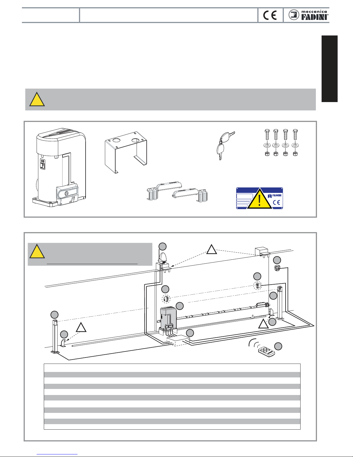
Anchor bracket
Nameplate
Screws xing the motor to
the anchor bracket
Coded key for the
release handle
Nyota 115 evo
FADINI
FADINI
GENERAL DESCRIPTION OF THE PRODUCT
Nyota 115 evo is an electromechanical operator to open and close sliding gates of any design and size up to a maximum weight of
1.850 kg. Two distinct voltage versions are available, single- and three-phase, both include 0,5 HP and 1,0 HP motors.
The Nyota 115 evo operators have steel-bronze mechanical coupling ie. worm and crown gear in an oil bath ; all supported by radial
bearings and thrust ball bearings to ensure the utmost in product reliability. The entire body and the cover are made of painted
pressure cast aluminium. The operator comes either in the version with incorporated control board (Elpro 12 evo) or stand alone
control box (Elpro 37/37 DS). Some accessories are required to ensure full safety and control of the system and make this operator
suitable to any application, in both public and private installations.
COMPONENTS AND PARTS INCLUDED IN THE EQUIPMENT
Pic. 1
This symbol means that particular attention is to be paid to installation operations and rst running test.
Failing to respect such indications may aect the functioning of the Nyota 115 evo gate operator.
!
madein It aly
www.fadini.net
installatore:
Data:
Modello:
N° serie:
CANCELLO AUTOMATICO
l’apricancello
!
Position Description Type of electric cable
MIRI 4 asher with Birio A8 aerial
FIT 55 photocell receiver
Nyota 115 evo c/ Elpro 12 evo n. VIX 53 radio plugin card
FIT 55 photocell projector
CHIS 37 keyswitch
Post for Fit 55 photocell receiver
Ground stop in closed and open gate positions
Electric cable junction box
Post for FIT 55 photocell projector
VIX 53 transmitter
2 x 0,5 (FROR CEI 20-20-EN 50267-2-1), RG58 for aerial
4 x 0,5 (FROR CEI 20-20-EN 50267-2-1)
supply voltage 3 x 1,5 (FROR CEI 20-20-EN 50267-2-1)
2 x 0,5 (FROR CEI 20-20-EN 50267-2-1)
4 x 0,5 (FROR CEI 20-20-EN 50267-2-1)
4 x 0,5 (FROR CEI 20-20-EN 50267-2-1)
2 x 0,5 (FROR CEI 20-20-EN 50267-2-1)
Indicative general layout: Nyota 115 evo with Elpro 12 evo. It is the installer’s care laying the piping for the electrical connections in the correct and proper way.
ELECTRICAL WIRING PREPARATIONS AND ACCESSORIES
Pic. 2
!!
!
6
1
2
3
5
4
7
78
9
1
2
3
4
5
6
7
8
9
10
!
The system is to be 230 V - 50 Hz power supplied and the
mains has to go through a magneto-thermal, dierential,
0,03 A circuit breaker (2,5 mm² cable beyond 100 m).
The entire installation must be properly grounded.
10
English
electromechanical operator for sliding gates
Nyota 115 evo
13
Magnetic limit switch brackets,
right- and left-handed
English
electromechanical operator for sliding gates
Nyota 115 evo
14
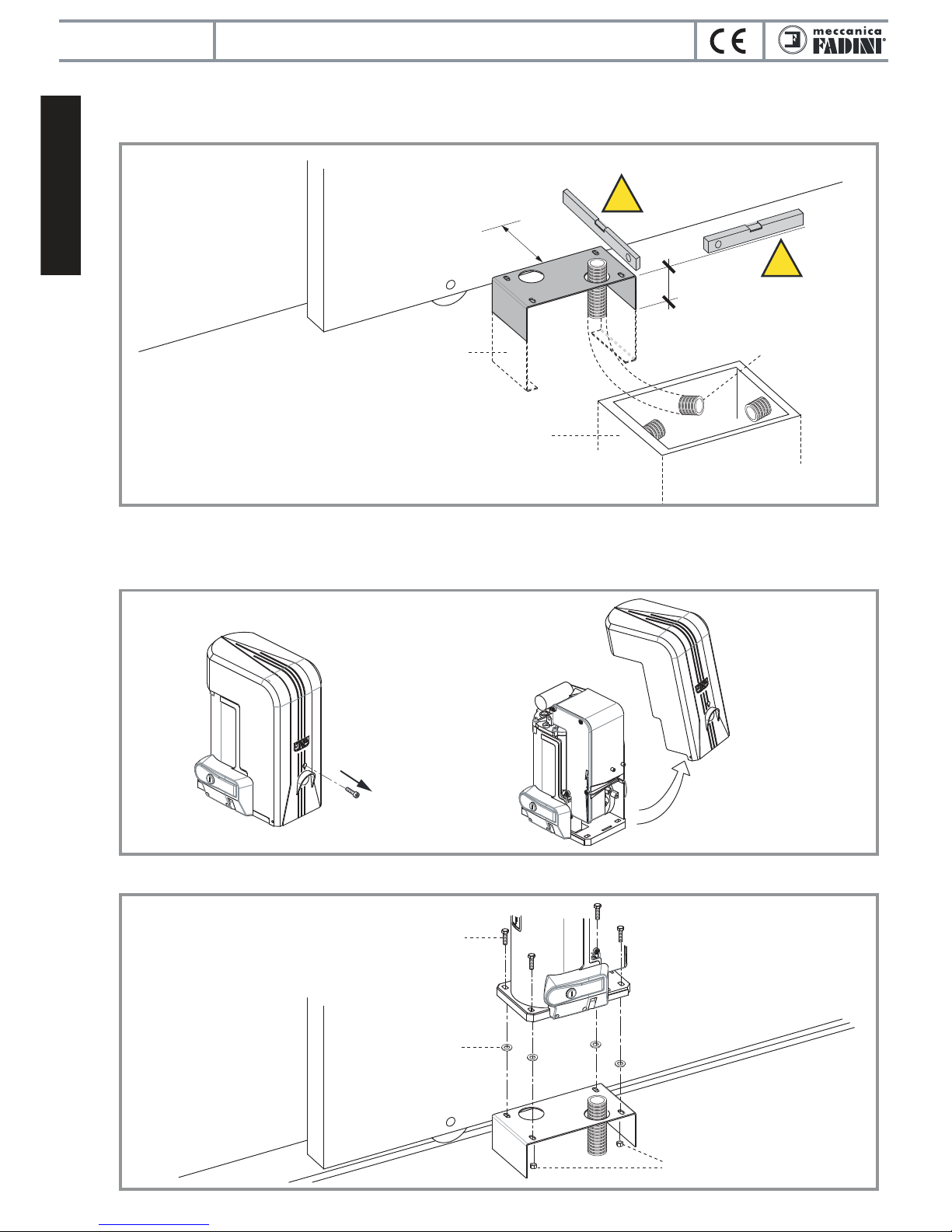
Pic. 3
Fig. 4
Pic. 5
CEMENTING THE ANCHOR BRACKET
MOUNTING NYOTA 115 EVO ONTO THE ANCHOR BRACKET
Inspectable
junction
pit
Pipes for
the electric
cables
Anchor bracket
to be cemented
into a ground
foundation
80
70
Distances in Pic. 3 are to be followed in this step. Once satised that concrete has rmly set all around the the bracket,
Nyota 115 evo can be mounted onto it.
Cover removing: unscrew the fastening screw completely (Pic. 4), then pull at the bottom in order to remove the cover.
Before fastening Nyota 115 evo by the provided screws, insert the washers under the operator: they will be removed once the
gear rack has been installed. In this way a 2 mm clearance is obtained between the rack teeth and the operator pinion (Pic. 5).
!
!
Washers
to be used as
distance parts
in installing phase
M8 fastening
screw
Cover
fastening
screw
M8 nut

English
electromechanical operator for sliding gates
Nyota 115 evo
15
FIXING THE GEAR RACK TO THE GATE
Before moving to the next step, gear rack xing, it is required that the engaging pinion is released and be able to turn
free. This will facilitate the xing of the gear rack modules.
Use the coded key to unlock the ap cover (release handle), then rotate it beyond 90° to disengage the pinion. To lock
back the operator, carry out the same steps in reverse order. Then slide the gate, to which the gear rack has been xed,
to mesh the pinion until the locking system is engaged.
Fix the gear rack modules all along the gate to coincide with the actually required gate travel. By means of a spirit level,
make sure they are well aligned, and take also into account the space needed for xing the limit switch striking plates at
both ends of the gear rack.
IMPORTANT: use a module as counter gear rack to make sure that junctions have the same pitch.
Once satised with the gear rack xing, remove the washers under Nyota 115 evo, in order to get a sucient clearance
between the operator pinion and the gear rack: the gate must be able to slide all its travel free of any friction.
Counter gear rack
!
Washers
M8 xing
screws
M8 nut
Electric
cables inlet
Pic. 6
Pic. 7
Pic. 8
FADINI
FADINI
Threaded
pin
Spacer
Fixing
screw
English
electromechanical operator for sliding gates
Nyota 115 evo
16
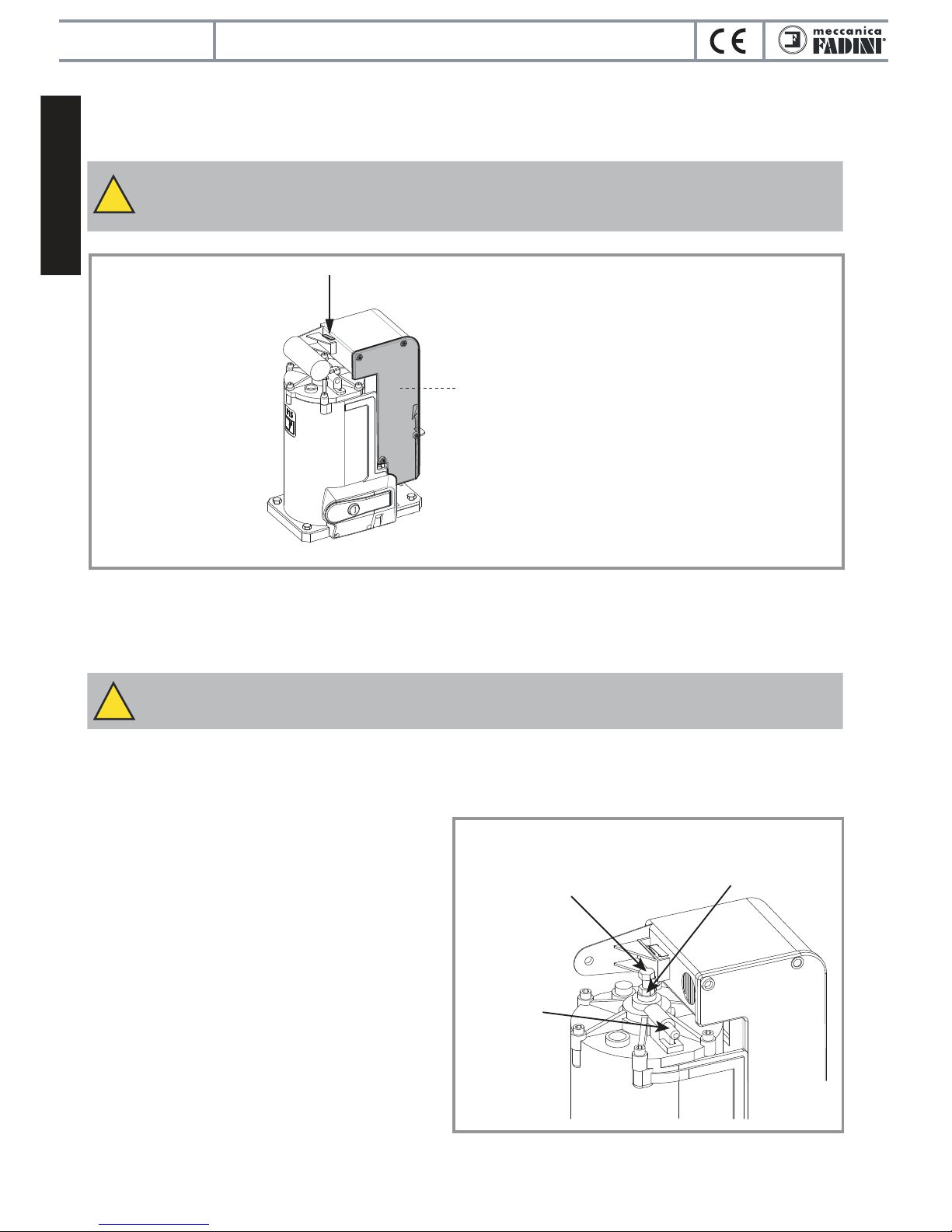
ELECTRICAL CONNECTIONS TO THE CONTROL BOARD
Nyota 115 evo is available either in the version with Elpro 12 evo control board incorporated or Elpro 37/37 DS stand alone.
The electrical connections are to be made following the instructions in the respective controller’s manual.
NOTE WELL: Nyota 115 evo is supplied with electric power when the safety micro-switch (positioned on the
upper part of the geared motor) is pressed and held down by the aluminium operator cover when this is tted
and rmly xed.
!
Pic. 9
The version Nyota 115 evo with
incorporated Elpro 12 evo
control board requires that the
lid be removed to access the
terminal strips
TORQUE ADJUSTING
The torque of Nyota 115 evo can be adjusted either by mechanical clutch or by Elpro 12 evo electronic control board, depending
on which model has been purchased.
NOTE WELL: the Nyota 115 evo models that are not equipped with either the encoder or the Elpro 12 evo
electronic control board require that torque be adjusted by the mechanical clutch system.
!
- torque control by Elpro 12 evo:
The Elpro 12 evo instructions manual is to be referred to.
- torque control by mechanical clutch:
ADJUSTING SCREW:
SCREW = + TORQUE
UNSCREW = - TORQUE LOCKNUT
RETAINING
PIN
Pic. 10
The clutch that controls torque in Nyota 115 evo is
completely in an oil bath and is to be adjusted in
accordance with the weight of the gate.
A 13 mm wrench is to be used to adjust (Pic. 10):
1) Press and hold the retaining pin
2) By means of a 13 mm wrench unscrew the locknut
(the retaining pin will hold the motor shaft steady)
3) Hold the retaining pin pressed and screw in the
adjusting screw (+ torque) or unscrew it (- torque)
4) Tighten the locknut until the adjusting screw is
securely locked
5) Release the retaining pin.
Safety microswitch

MOUNTING THE MAGNETIC LIMIT SWITCH BRACKETS
NOTE WELL: DO NOT OPEN THE BRACKETS TO REVERSETHE ARRAY OF THE INNER MAGNETS; THEY ARE
PROPERLY PRE-ARRANGED FOR THE LOGIC CONTROL BOARD TO IDENTIFY THEM.
!
NOTE WELL: IT IS FUNDAMENTAL THAT THE GATE DOES NOT RUN INTO THE GATE STOPS TOO FAST ON
OPENING AND CLOSING CYCLES; A 30-50 mm CLEARANCE SHOULD BE RECOMMENDED BEFORE THE
LIMIT SWITCHES ARE ENGAGED.
!
electromechanical operator for sliding gates
Nyota 115 evo
5 mm
Pic. 11
Pic. 12
!
!
Limit switch
right-hand
DX bracket
Limit switch
left-hand
SX bracket
Open
gate stop
Close
gate stop
30 - 50 mm
English
!30 - 50 mm
17

English
electromechanical operator for sliding gates
Nyota 115 evo
ELECTRICAL CONNECTIONS TO THE MAGNETIC LIMIT SWITCH
NOTE WELL: rst of all identify the position of Nyota Evo in relation to the opening direction of the gate view
from inside (on the left or right). Depending on this, properly connect the brown and green wires of the limit
switch and the wires of the electric motor.
NOTE WELL: Nyota Evo in the version with incorporated Elpro 12 Evo control board comes factory pre-wired
as if it were going to be installed on the left.
In case Nyota Evo is required to be installed on the left, swap the connections to terminals 8 - 10 and 16 - 18.
!
Magnetic
limit switch
sensor
Nyota 115 evo
mounted on the left
Elpro 12 evo
Elpro 37
Elpro 37 DS
Elpro 37 FN
Elpro 12 evo
Elpro 37
Elpro 37 DS
Elpro 37 FN
Nyota 115 evo
installed on the right
Magnetic
limit switch
sensor
common
black
brown
green
blue
18
Pic. 13
Pic. 14
MOUNT ON THE RIGHT
MOUNT ON THE LEFT
M
common
M
17
18
16
12/24 Vac/dc
810
12 13
!
Closing LSW
Opening LSW
black
blue
brown
black
brown
green
blue
common
black
blue
brown
12/24 Vac/dc
10
8
12 13
comune
16 17 18
!
Closing LSW
Opening LSW

electromechanical operator for sliding gates
English
Nyota 115 evo
19
hand over to the end user of the installation
MAINTENANCE RECORD
hand over to the end user of the installation
Installation address:
Installation type:
Sliding gate
Over-head door
N°
1
2
3
4
5
6
Service date
Stamp and signature
installation technician/maintainer
Signed for acceptance
end user
buyer
Technical maintainer End user/sService description
Lateral folding
door
Swinging gate
Folding door
Bollard
.............................
Road barrier
Operator model:
Dimensions per gate leaf:
Weight per gate leaf: Installation date:
Quantity of models
installed:
Maintainer: Date:
NOTE WELL: this document must record any ordinary and extraordinary services including installation, maintenance,
repairs and replacements to be made only by using Fadini original spare parts.
This document, for the data included in it, must be made available to authorized inspectors/ocers, and a copy of it must
be handed over the end user/s.
The installer/maintainer are liable for the functionalities and safety features of the installation only if maintenance is
carried on by qualied technical people appointed by themselves and agreed upon with the end user/s.
the gate opener
X
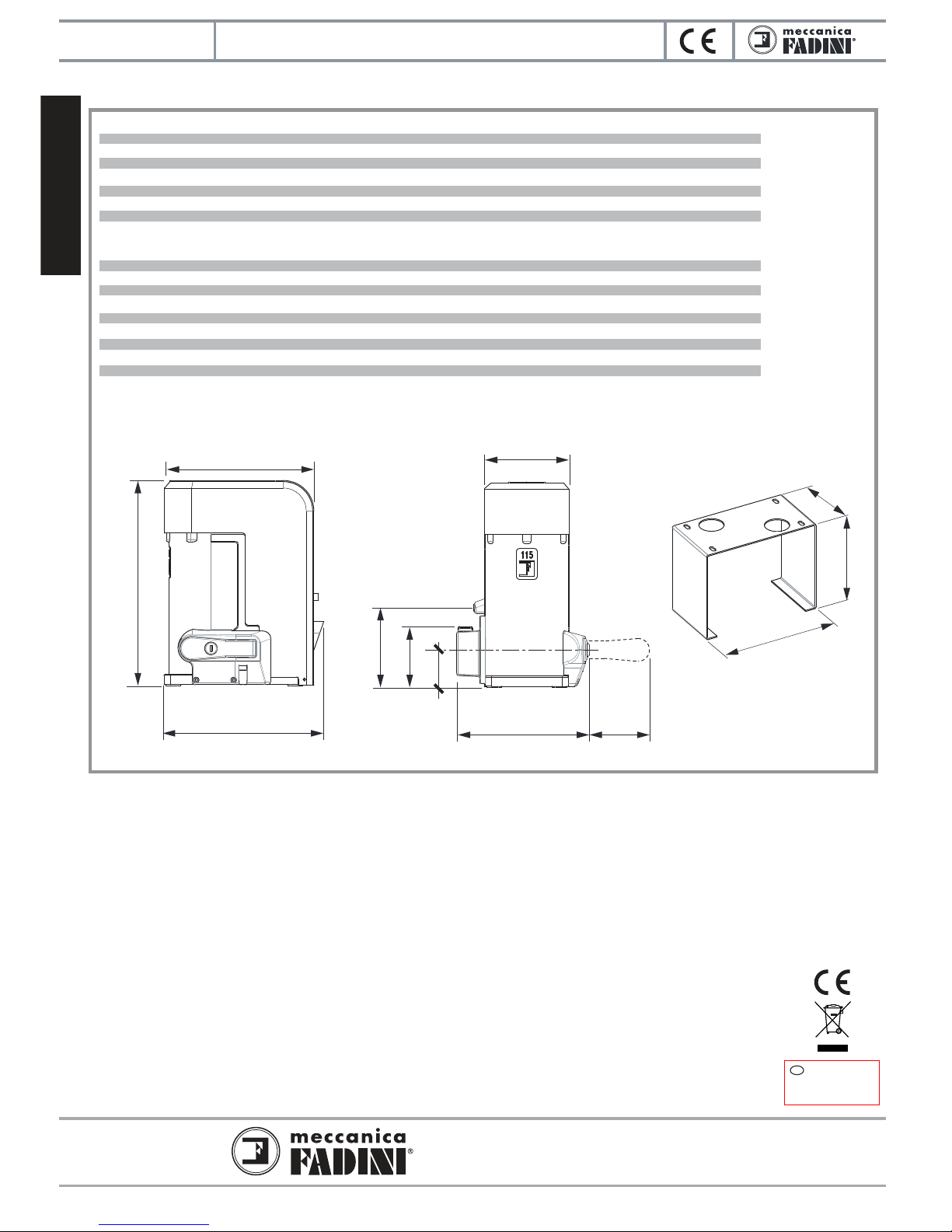
ELECTRIC MOTOR
1-phase 0,5 HP
Power output 0,37 kW
Absorbed power 600 W
Supply voltage 230 Vac - 50 Hz
Absorbed current 3,2 A
Motor revolutions 1.380 rpm
Capacitor 30 µF
Intermittent service S5
GEAR BOX
Rated torque 40 Nm
Gear ratio 1:32
Travel speed 10 m/1’
Working temperature -25 °C +80 °C
Protection standards IP 55
Nyota 115 evo weight 18,5 kg
Gate max. weight (*) 1.200 kg
Frequency of use very intensive
Oil type FADINI OIL code 706L
40 Nm
1:32
10 m/1’
-25 °C +80 °C
IP 55
18 kg
1.250 kg
very intensive
FADINI OIL code 706L
(*) The gate structure, shape and wheels may aect the a.m. values . Always make sure the gate is adequate to be automatically
operated and remove any possible friction points.
80 Nm
1:32
10 m/1’
-25 °C +80 °C
IP 55
20 kg
1.800 kg
very intensive
FADINI OIL code 706L
80 Nm
1:32
10 m/1’
-25 °C +80 °C
IP 55
19,5 kg
1.850 kg
very intensive
FADINI OIL code 706L
3-phase 0,5 HP
0,37 kW
575 W
230/400 Vac - 50 Hz
2,1/1,2 A
1.380 rpm
/
S5
3-phase 1,0 HP
0,73 kW
1.030 W
230/400 Vac - 50 Hz
3,7/2,2 A
1.380 rpm
/
S5
1-phase 1,0 HP
0,73 kW
1.130 W
230 Vac - 50 Hz
5,7 A
1.380 rpm
30/40 µF
S5
TECHNICAL DATA
260
200
140
278 mm
352
257
English
electromechanical operator for sliding gates
Via Mantova, 177/A - 37053 Cerea (VR) Italy
Ph +39 0442 330422 Fax +39 0442 331054
info@fadini.net www.fadini.net
Nyota 115 evo
20
2012/19/UE Directive
Disposal of electric and
electronic equipment
DISPOSE PROPERLY OF MATERIALS
ARMFUL TO THE ENVIRONMENT
GB
62
223 96
145
104
138
2018/07
This manual suits for next models
3
Table of contents
Other Meccanica Fadini Gate Opener manuals


Popular Gate Opener manuals by other brands


RIB
RIB PRINCE 24V Operator's manual

GTO
GTO 4000XL Hec1005a

Nice
Nice Wingo4024 Instructions and warnings for installation and use

Becker
Becker M04 Assembly and operating instructions

CAME
CAME FE4024 installation manual

Roger Technology
Roger Technology BH30 Series INSTRUCTIONS AND RECOMMENDATIONS FOR THE INSTALLER