MECHAPRO Tiny-Step User manual

Assembly Instructions
Stepping Motor Board >Tiny-Step<
Rev. 1.0 (last updated 15.07.2008)
Functional description:Functional description:
Functional description:Functional description:
Functional description:
Tiny-Step is a 1 channel stepping motor driver, that can drive motors with up to 2.25 amperes
(peak) in full-, half-, fourth- or eighth-step mode. The board is based on the A3977 that
supports all features of microstep signal generation and includes the amplifier. The signal /
SLEEP can reduce motor current by 25%. The /e-STOP signal switches off the amplifier
directly. The HOME-LED signals every fourth full step for a simple signal in case steps are lost.
The board is delivered partially fitted with components (all SMD parts).
DisclaimerDisclaimer
DisclaimerDisclaimer
Disclaimer, EMC-compliance, EMC-compliance
, EMC-compliance, EMC-compliance
, EMC-compliance
Even though all parts of the circuitry have been thoroughly checked and tested, mechapro
does not give any warranty or other assurance as to the operation or functionality of the
circuitry or the documentation.
To the full extent permissible by law we disclaim all responsibility for any damages or losses
(including, without limitation, financial loss, damages for loss in business projects, loss of profits
or other consequential losses) arising from the use or reproduction and/or operation of the
presented circuitry.
The stepper motor driver card Tiny-Step is an OEM-product for further processing by industry
or other, in electronics specialized, personal. In line with §5 of the EMC-regulation the Tiny-
Step driver card does not have to carry a CE-Label. Wiring and the individual components
being used as well as the complete environment in which the controller card is operated will
influence its EMC behaviour. Therefore, if CE-compliance is required, a system in which one or
more Tiny-Step driver cards have been installed for operation has to be evaluated as a whole
unit. Of course, when developing the circuitry for the Tiny-Step all possible aspects for an
EMC-suitable design have been taken into account.
Fitting with ComponentsFitting with Components
Fitting with ComponentsFitting with Components
Fitting with Components
- Start with the small components (resistors, diodes, capacitors, ...)
- Be careful to assemble with correct polarity (diodes, electrolytic capacitors, ...)
- The ICs should be mounted on sockets as a precaution.
- A heat sink is not necessary. The amplifier is cooled by a thermal ground pad on the board. In
use, depending on the environment, it may be necessary to use an additional fan for cooling.
If the casing is already well ventilated, it may not be necessary to use an additional fan, if the
board is mounted in the air-stream.
Initial OperationInitial Operation
Initial OperationInitial Operation
Initial Operation
- Before first use, the assembly and all solder points should be carefully checked! Are all ICs
mounted in the correct direction? All cables on the NCS-BUS and the solder points should be
checked for short circuits.
ostermann@mechapro.de • www.mechapro.de
Adress: Theaterplatz 6-8 • 52062 Aachen • Germany
Layout diagramLayout diagram
Layout diagramLayout diagram
Layout diagram
DimensionsDimensions
DimensionsDimensions
Dimensions

• The jumpers should be set to the default values as described below.
• Start with only the 5V logic supply (via NCS-BUS) - without applying power to the motors
and with no other connections (PC, Motors).
• Set the reference voltage for the Motor current with the R16 trimmer. The voltage can be
measured between the TEST pins. The measured voltage V(ref) depends on the motor
current (effective value) in the following way:
V(ref)=2*Squareroot(2)*Ieff(Motor)=2,83*I(Motor) equals the nominal value for the line
current. The peak current Ipeak is greater by the factor of Squareroot(2) - (max. 2,25A). For
1,5Aeff for example you would set the system to 4,24 volts.
• When all of this has been tested and verified, the board can be tested with a motor.
To do this, connect the board to the PC or microcontroller board. Always start up the PC first,
then start the software and then switch on the power supply for the board!
During boot up the power levels of some signal levels can change, that can cause undesired
reactions. For tests a free demo (for example PCNC) or a small self written program is
recommended.
If possible, start by applying a small voltage to the motor (15-20V), from a current limiting
power supply.
JP1: Step DividerJP1: Step Divider
JP1: Step DividerJP1: Step Divider
JP1: Step Divider
Jumper JP1.2 JP1.1
Full Steps closed closed
Half Steps open closed
1/4 Steps closed open
1/8 Steps open open
JP2: External rectificationJP2: External rectification
JP2: External rectificationJP2: External rectification
JP2: External rectification
The default setting (jumper set to 2-3) disables the „synchronous rectification“, and so
reduces power dissipation in the device. When no external diodes are used, change jumper
setting to 1-2. Caution: The maximum current of the board will be lowered in this
configuration!
External ConnectionsExternal Connections
External ConnectionsExternal Connections
External Connections
• The motor is connected to the screw connectors X1 (1. Coil) and X2 (2. Coil). The rotational
direction of the motor can be changed by reversing the polarity of one coil.
Center pins of unipolar motors (with 5 or 6 pins) are not connected. The pins must be
insulated and may not be connected to the positive supply or ground in any case!
Bipolar motors with 8 pins provide the possibility to connect two coil pairs in series or in
parallel. In series will always work. Connecting the coils in parallel may allow faster revolutions,
however the current is doubled as well (in comparison with the serial setup). The coil
resistance is halved in this case and the coil resistance should not be below 0.8 Ohms.
•To connect the board to the PC an interface board with a seperate connection for End-
point- and Emergency-Off-Switches is available. Alternatively an adapter cable can be used.
• When no interface board is used, pull all inputs of the board to VCC/+5V (or to ground) with
pullup resistors (10-47k).
Pinout of CON1 (NCS-BUS)Pinout of CON1 (NCS-BUS)
Pinout of CON1 (NCS-BUS)Pinout of CON1 (NCS-BUS)
Pinout of CON1 (NCS-BUS)
1not connected (n.c.)
2/Clock (Clock signal, falling edge generates a step)
3not connected (n.c.)
4/CCW (rotational direction, counterclockwise at low-level)
5/Emergency Off (at low-level)
6/Sleep (current reduction to 25% of the nominal current at low-level)
7,8 VCC (+5 Volts)
9,10 Ground
Meaning of LEDsMeaning of LEDs
Meaning of LEDsMeaning of LEDs
Meaning of LEDs
POWER: Turns on as soon as 5 Volts are applied to CON1
HOME: Lights up at every fourth full step position (Home position)
Hints for THints for T
Hints for THints for T
Hints for Troubleshootingroubleshooting
roubleshootingroubleshooting
roubleshooting
- If any part of the circuit does not work after first assembly, or when a failure occurs, find
and fix the error, before connecting or running a motor with the circuit! These additional hints
may be of help:
If these hints and the additional help at www.NC-Step.de don’t answer all your questions,
contact me for further help, by email. Please provide a detailed description of the problem
and your configuration. (Power supply, used Software a.s.o.) -> E-Mail: Ostermann@NC-
Step.de
Component List (without SMD-Parts)Component List (without SMD-Parts)
Component List (without SMD-Parts)Component List (without SMD-Parts)
Component List (without SMD-Parts)
Qty.Value Package Parts
81R R-EU_0207/10 R1, R2, R3, R4, R5, R6, R7, R8
8BYV27 BYV27 D1, D2, D3, D4, D5, D6, D7, D8
11K R-TRIMMT18 R16
1BC557B BC557B Q1
1lcLED yellow - home LED3MM LED1
1lcLED green - power LED3MM LED2
110µF/35V CPOL-EUE2.5-5 C10
1100µF/63V CPOL-EUE5-10.5 C11
1Pinh. 1*2 JP1E TEST
1Pinh. 1*3 JP2E JP2
1Pinh. 2*2 JP2QE JP1
1Connector-ML 10pol. ML10 CONTROL
2Pinhead 10pol.
3Screw Connector W237-02P X1, X2, X3
1DIL8 IC-Sockel
1DIL14 IC-Sockel
3Jumper
1TLV272IP TLV272IP IC3
174HCT14N 74HC14N IC1
0,5m ribbon cable 10pol.
Additional NotesAdditional Notes
Additional NotesAdditional Notes
Additional Notes
- A well stabilized motor voltage saves time and work, when searching for errors and reduces
noise levels. (Rule of thumb: 10.000µF for 3 motors (a lot helps a lot ;-)
- The 1 kOhm SMD resistors (R20, R21) should be adjusted according to the used LEDs if low
current LEDs are not used (Approximation: (5V - U_Diode)/I_Diode = R, e.g. (5V-1V) / 15mA =
270 Ohm).

notesnotes
notesnotes
notes
TT
TT
Technical Dataechnical Data
echnical Dataechnical Data
echnical Data
Power Supply (Logic): 5 Volts +/- 5%
Power Drain (Logic): typical 75mA, maximum 100mA
Power Supply (Power Element):15-35 Volts
Power Drain (Power Element): dependent on Power Supply Voltage, Motor current and
used Motor. Maximum Continuous Current: 2 Amperes.
Control: Clock- and Direction signals, CMOS-compatible.
Step Resolution: Full-, Half-, 1/4th and 1/8th-Steps
Outputs: 1 stepping motor channel up to 1.6/2.25A (effective/peak)
per coil, not short circuit protected

Popular Carrier Board manuals by other brands

Diamond Systems
Diamond Systems Jackson JAX-BB01 user manual
ICM Controls
ICM Controls ICM2920 Installation, operation & application guide
IBM
IBM Power System 5105-22E manual

Arbor Technology
Arbor Technology PBN-9007 Quick installation guide
Seco
Seco COM-Express CCOMe-C79 user manual
AXIOMTEK
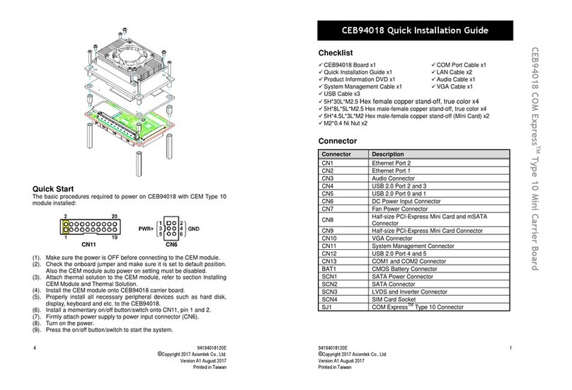
AXIOMTEK CEB94018 Quick installation guide
