manuals.online logo
Brands
  1. Home
  2. •
  3. Brands
  4. •
  5. AXIOMTEK
  6. •
  7. Carrier Board
  8. •
  9. AXIOMTEK CEB94018 User manual

AXIOMTEK CEB94018 User manual

4 94194018120E
©
Copyright 2017 Axiomtek Co., Ltd.
Version A1 A g st 2017
Printed in Taiwan
Quick Start
The basic procedures required to power on CEB94018 with CEM Type 10
module installed:
CN11 CN6
(1). Make sure the power is OFF before connecting to the CEM module.
(2). Check the onboard jumper and make sure it is set to default position.
Also the CEM module auto power on setting must be disabled.
(3). Attach thermal solution to the CEM module, refer to section Installing
CEM Module and Thermal Solution.
(4). Install the CEM module onto CEB94018 carrier board.
(5). Properly install all necessary peripheral devices such as hard disk,
display, keyboard and etc. to the CEB94018.
(6). Install a momentary on/off button/switch onto CN11, pin 1 and 2.
(7). Firmly attach power supply to power input connector (CN6).
(8). Turn on the power.
(9). Press the on/off button/switch to start the system.
CEB94018 Quick Installation Guide
94194018120E 1
©
Copyright 2017 Axiomtek Co., Ltd.
Version A1 A g st 2017
Printed in Taiwan
Checklist

C
EB94018
Board x1

COM Port
Cable
x1

Q
uick Installation Guide
x1

LAN Cable x2

Product Information
DV
D
x1

Audio Cable x1

System Management Cable x1

VGA Cable x1

U
SB Cable x3
5H*30L*M2.5
Hex f
emale copper stand
-
off, true color
x4

5H*8L*5L*M2.5
Hex male
-
female copper stand
-
off, true color
x4

5H*4.5L*3L*M2
Hex male
-
female copper stand
-
off
(Mini Card) x2

M2*0.4 Ni Nut x2
Connector
Connector Description
CN1
Ethernet
Port 2
CN2
Ethernet
Port 1
CN3
Audio
Connector
CN4
USB 2.0 Port
2
and
3
CN5
USB 2.0 Port
0
and
1
CN6
DC Power Input Connector
CN7
Fan Power Connector
CN8 Half-size PCI-Express Mini Card and mSATA
Connector
CN9
Half
-
size
PCI
-
Express Mini Card Connector
CN10
VGA
Connector
CN1
1
System Management Connector
CN12
USB 2.0 Port
4
and
5
CN13
COM1 and COM2 Connector
BAT1
CMOS Battery Connector
SCN1
SATA Power
Connector
SCN2
SATA
Connector
SCN3
LVDS and Inverter Connector
SCN4
SIM Card Socket
SJ1
COM Express
TM
Type 10
Connector
CEB94018 COM Express
TM
Type 10 Mini Carrier Board
2 94194018120E
©
Copyright 2017 Axiomtek Co., Ltd.
Version A1 A g st 2017
Printed in Taiwan
Jumper Settings
Before applying power to the CEB94018, please make sure onboard JP2 is
in factory default positions.
Jumper Description Setting
JP2
LVDS +3.3V/+5V Voltage Selection
Default: +3.3V
3-5 Close
Restore BIOS Optimal Defaults
Default: Normal Operation
4-6 Close
Note: Please refer to the product information DVD for the complete user’s
manual, drivers and utilities. User’s manual and related documents are
in Acrobat PDF format.
Please contact your local vendors if any damaged or missing items. DO
NOT apply power to the board if there is any damaged component.
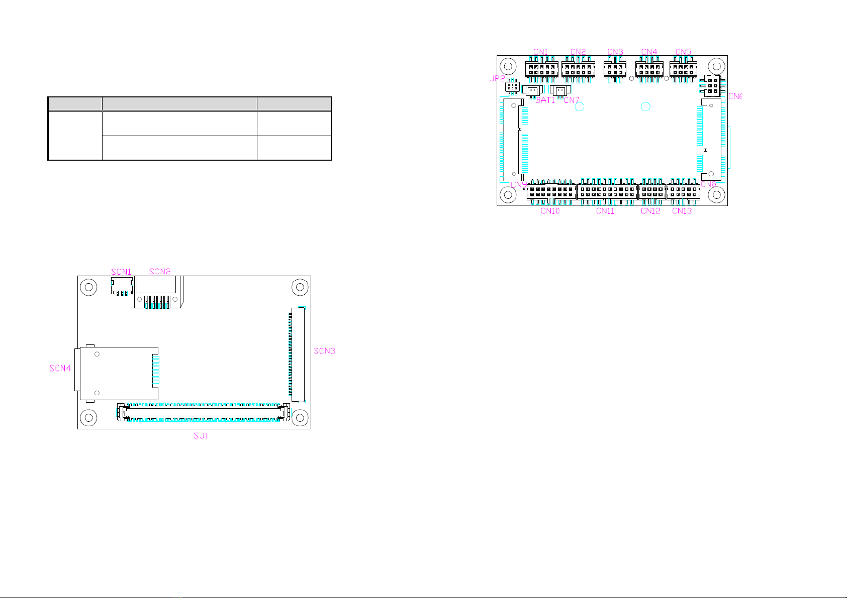
Module Layout
Top View
94194018120E 3
©
Copyright 2017 Axiomtek Co., Ltd.
Version A1 A g st 2017
Printed in Taiwan
Bottom View
Installing CEM Module and Thermal Solution
For thermal dissipation, a thermal solution enables the components on the
CEM module to dissipate heat efficiently. All heat generating components
are thermally conducted to the heatsink in order to avoid hot spots. Below
images illustrate how to install the thermal solution.
1. Each thermal solution is designed for a specific CEM module. The
thermal pads on the heatspreader are designed to make contact with
the necessary components on the CEM module. When mounting the
heatspreader you must make sure that the thermal pads on the
heatspreader make complete contact (no space between thermal pad
and component) with the corresponding components on the CEM
module. This is especially critical for CEM modules that have higher
CPU speeds (for example 1.46GHz or more) to ensure that the
heatspreader acts as a proper thermal interface for cooling solutions.
2. There is a protective plastic covering on the thermal pads. This must
be removed before the heatspreader can be mounted. Before installing
the heatspreader to the CPU module, please apply thermal grease on
the CPU die. This CPU module has four assembly holes for installing
heatspreader plate. Use the four screws to secure the heatspreader
plate. Be careful not to over-tighten the screws. Then, apply thermal
grease at the bottom of heatsink and secure the heatsink on the
heatspreader by another four screws.
The headspreader and heatsink
will be provided according to different CEM module.

Popular Carrier Board manuals by other brands

ESD PCIe-XPIMC-Carrier Hardware manual

ESD

ESD PCIe-XPIMC-Carrier Hardware manual

Emerson COMX-CAR-610 COM Express Installation and use

Emerson

Emerson COMX-CAR-610 COM Express Installation and use

EMAC CPC-2420 user manual

EMAC

EMAC CPC-2420 user manual

RTimes RTSO-6003 product manual

RTimes

RTimes RTSO-6003 product manual

SMARC ALPHA SoM Series Hardware manual

SMARC

SMARC ALPHA SoM Series Hardware manual

ADLINK Technology miniBASE-10R user manual

ADLINK Technology

ADLINK Technology miniBASE-10R user manual

Auvidea JNX30D Technical reference manual

Auvidea

Auvidea JNX30D Technical reference manual

Aaeon ECB-920A-A11 user manual

Aaeon

Aaeon ECB-920A-A11 user manual

Apex Digital ACC500-DLX owner's manual

Apex Digital

Apex Digital ACC500-DLX owner's manual

sparkfun ZED-F9P HOOK-UP GUIDE

sparkfun

sparkfun ZED-F9P HOOK-UP GUIDE

Caen ELS DAMC-FMC20 user manual

Caen ELS

Caen ELS DAMC-FMC20 user manual

Supermicro BPN-ADP-2M2-1UB manual

Supermicro

Supermicro BPN-ADP-2M2-1UB manual

Connect Tech Sprocket Carrier user manual

Connect Tech

Connect Tech Sprocket Carrier user manual

manuals.online logo
manuals.online logoBrands
  • About & Mission
  • Contact us
  • Privacy Policy
  • Terms and Conditions

Copyright 2025 Manuals.Online. All Rights Reserved.