manuals.online logo
Brands
  1. Home
  2. •
  3. Brands
  4. •
  5. Mecmesin
  6. •
  7. Test Equipment
  8. •
  9. Mecmesin Vortex User manual

Mecmesin Vortex User manual

Vortex
Motorised Test Stand
Operating Instructions
It is essential that you
familiarise yourself with the
contents of these instructions
before attempting to
operate the Vortex
431-124 / 01
S.I. Instruments
256 South Rd. Hilton
South Australia 5033
Ph (08) 8352 5511
[email protected]
www.si-instruments.com
Thank you for choosing this Mecmesin instrument. With correct use it will give many years
of reliable service. Upon receiving the unit please check that no obvious physical damage
has been sustained by the packaging material or the instrument itself. If any damage is
evident, or if any of the items in Appendix 1 are missing, please notify Mecmesin or their
Authorised Agent immediately. We strongly recommend that all the packaging and fixings
are retained for any future transit requirements.
When using the Vortex please ensure that the ventilation holes situated on the back and
bottom of the unit are not obstructed.
Appendix 2 gives guidance notes on the safe use of mains powered test frames. You
should read this before proceeding any further.
Failure to adhere to the guidelines for safe use given in these operating instructions may
result in irreparable damage to the unit and personal injury to the operator.
The Vortex is a motorised torque measuring instrument with a rated capacity of 10N.m and
a speed range of 0.5 to 15rpm. It enables a repeatable and constant test speed to be set,
so reducing variability in test results caused by operators manually performing tests at
different speeds.
The torque is measured on the Vortex by means of a static transducer mounted on a
moveable crosshead and connected to an AFTI display (Advanced Force/Torque Indicator).
The functionality of this digital display is outlined in the separate manual enclosed.
Please note that the AFTI will not function if the transducer is not connected securely.
In addition to the digital display of torque, speed is also displayed digitally during the test.
This is switchable with a display of total angular rotation if required.
Some testing requires the sample to be pre-loaded axially in order to enable the torque to
be measured, as with a child resistant container of the push and twist type (ASTM D3475
type 1A or 11A). The transducer can accept up to a maximum of 5Kg axial loading. Weights
should be placed in the platen at the top of the adjustable column. Please ensure any
weights are safe and secure prior to commencement of testing.
To carry out testing, the sample under evaluation needs to be gripped securely in the top
and base fixtures. Both are fully adjustable and the most appropriate position can be found
by positioning the rubber pegs in the threaded runners and then tightening. Results can be
affected if the sample is not squarely held during the testing process. Please contact
Mecmesin for cost and availability of dedicated gripping mechanisms, if required.
SAFE OPERATION OF THE VORTEX
INTRODUCTION TO THE VORTEX MOTORISED TESTER
Speed Setting
The Vortex has a variable speed control which should be referenced against the speed and
rotation display. It is advisable to perform a speed check prior to the actual test to ensure
that the correct speed has been selected.
Speed & Rotation Display
The display will allow either actual speed or degrees of rotation to be displayed. The
required option is selected by pressing the SEL button on the left hand side of the display.
If the degree option is selected then the display will count up continuously with each
revolution e.g. 1.5revs = 540 degrees.
The RST button on the right of the display will reset the degrees of rotation at the point it is
depressed.
Enable Button
The Vortex will only operate when the enable button is depressed in conjunction with the
activation of the direction control. This two handed operation is designed as a safety
feature to ensure that the operator’s hands are clear of the base fixture.
Once moving, the base fixture will stop rotating if: -
1. The enable button is released
2. The direction control is released
3. A pre-set alarm point is reached
4. The power is disconnected
Direction Control
Sets the direction for the rotation of the base fixture. To measure release torque on a right
hand thread the fixture must be rotated in a clockwise direction.
If you wish to stop the rotation of the base fixture using the alarm points on the AFTI then
you will require the optional vortex control cable (SA-MBTC03). This is plugged into the
“SEL” - Select “RST” - Reset
VORTEX FUNCTIONALITY
communication port of the display and the 15 way connector on the rear of the Vortex. This
will stop the vortex at the first alarm point reached (instructions for configuring the alarm
point can be found on page 6 of the AFTI manual).
Re-Set Button
The re-set button works only when used in conjunction with the control cable
(SA-MBTC03) and allows the torque reading on the AFTI to be re-set. The display must be
re-set if an alarm point is reached before the feature can be used again.
Emergency Stop
Pressing the emergency stop will cut power to the motor and stop rotation of the base
fixture. The power LED will remain illuminated as mains power is still being supplied to the
base unit. To release the emergency stop the red button needs to be rotated until it springs
back to the set position.
Vortex Basic Operation
Check that the correct speed has been selected for the test specification and that you know
the direction required to carry out the test.
The sample to be tested is located in the base fixture and firmly secured. Release the
adjustable column until the top fixture is in central contact with the top of the sample,
tighten the top fixture until secure.
If additional travel is required on the adjustable column to position the top fixture correctly
then the moveable crosshead must be lowered by releasing the thumbscrews and
lowering to the appropriate position. Ensure that the thumbscrews are re-tightened when
adjustment is complete.
Depress the enable button and activate the direction control. Once the test has been com-
pleted, release the direction control, this will stop the rotation of the base fixture.
Options
Some applications require a graphical representation of the test. This is usually necessary
if more than a maximum reading is to be recorded.
Mecmesin’s graphical charting software ‘DataPlot’ can be used in conjunction with the
Vortex via connection to the 9 way connector on the rear of the Vortex or directly via the
AFTI. Please contact Mecmesin sales on 01403 799979 for available cable and software
options.
Vortex Technical Specification
Load Capacity 10N.m / 100kgf.cm / 90lbf.in
Power consumption 80 watts (maximum)
Weight (stand only) 18kg (39lb)
Speed range 0.5 – 15rpm
Display resolution 1 : 5000
Sample diameters (base fixture) 20 – 195mm
Sample diameters (top fixture) 8 – 55mm
Data capture rate 1200Hz
Display update rate High 40Hz - Low 2Hz
Torque Accuracy ± 0.5% F.S.D. ± L.S.D.
Peak Hold 1st & Ultimate peak capture
in application & release modes
Battery Life (AFTI) Ni-cad battery pack 20 hours continuous use
between charges (8 hr recommended charge)
Data output Configurable RS232, Mitutoyo & analogue
Calibration temperature 20˚c ± 2˚c
Should you require any variation on the standard specification please contact Mecmesin
Sales on 01403 799979 or your local supplier for optional variations. Please note that
Mecmesin reserves the right to alter equipment specifications without prior notice.
Your Vortex should be supplied with the following accessories:
• These operating instructions
• Calibration Certificate (Torque only)
• Mains Adaptor for AFTI display
• Appropriate mains cable
• Operating instructions for AFTI
• 8 off threaded pillars, 4 long and 4 short
A GUIDE TO THE SAFE USE OF MAINS POWERED TEST FRAMES
MECMESIN TEST STANDS HAVE BEEN DESIGNED AND MANUFACTURED IN A CON-
TROLED SYSTEM TO ENSURE COMPLIANCE WITH ALL RELEVANT EUROPEAN
COMMUNITY DIRECTIVES.
APPENDIX 1
APPENDIX 2
Receiving and Unpacking
1. Upon receiving the Mecmesin test frame ensure adequate equipment is available to
safely lift the test frame from the packaging. Trying to lift heavy items without adequate
assistance or the correct equipment may lead to accidental personal injury.
2. Once safely removed from the packaging, place the test frame on a stable work surface.
Inspect the machine for any signs of obvious transit damage.
IF ANY DAMAGE IS DISCOVERED DO NOT GO ANY FURTHER WITH INSTALLATION
AND DO NOT CONNECT TO MAINS SUPPLY UNDER ANY CIRCUMSTANCES.
Contact your local supplier immediately who will decide the most appropriate action to rec-
tify the situation as quickly as possible.
Installing the Machine
1. After placing the machine on a stable and level work surface, check that the mains inlet
voltage corresponds to your electrical installation – either 230Vac or 110Vac.
The machine has a label close to the mains inlet connector, which advises the voltage it is
set for.
If the machine does not correspond to your supply, inform your local Mecmesin supplier
who will rectify the situation.
Connecting a mains powered test frame to the wrong supply will almost certainly
cause extensive damage to the equipment.
The Mecmesin test frames must only ever be connected to a mains power installation that
has a fully installed earthing system.
CONNECTING A MAINS POWERED TEST FRAME TO AN ELECTRICAL POWER OUT-
LET WITHOUT AN EARTH CONNECTION IS EXTREMELY DANGEROUS AND COULD
LEAD TO A RISK OF ELECTROCUTION.
2. After all the above points have been checked and confirmed to be correct you may
connect the machine to the mains outlet only with the supplied mains lead.
When power is applied the mains indicator light will illuminate. This shows power is
reaching the machine and is therefore ready for use.
Check its basic operation with reference to this operating manual.
Operator Training
1. Each person, who is to use the machine, should be fully trained in the safe use of the
motorised testing machines. The machine has the ability to generate forces large enough
to cause permanent damage to human limbs if not used correctly.
Always disconnect the machine from the mains power supply when not in use to avoid
inadvertent actuation of the machine by untrained personnel.
Protective Clothing
Eye protection should always be used in the form of an approved pair of safety spec-
tacles. They should be replaced if they are scratched or damaged in any way. They should
be kept clean and clear to give maximum visibility to the user.
Extra body protection may be necessary if destructive testing or volatile failure of a test
piece is likely. A risk assessment should be carried out prior to using the test frame to
ensure that all necessary safety measures have been considered and carried out.
Machine Guarding
If, after the assessment, it is considered that machine guarding is needed, then contact you
local supplier who, through the Mecmesin Application Engineering Department, can
arrange the supply of a suitable guard to offer the required level of protection.
Continued Safe Use
Once the machine is installed it should provide a reliable long term resource for torsional
testing. If however the machine fails, or appears to behave in an unusual manner, contact
you local supplier for support. Do not continue to use the machine until it has been checked
and if necessary, repaired and returned to a safe working condition.
If the machine is damaged in use, advise your local supplier and have the machine repaired
to a safe working condition. Do not use the machine until it is repaired.
CAUTION: Hands must be kept clear of the adjustable base fixture
at all times during machine operation
LIFTING INSTRUCTIONS: Before attempting to lift the Vortex, turn off the power switch
and unplug from the mains.
IF IN DOUBT CONSULT YOU LOCAL SUPPLIER
TO ENSURE CONTINUED SAFE USE
Vortex Motorised Torque Tester
14
3
4
5
6
7
8
13
2
10
11
12
9
Key:
1 Top platten
2 Adjustable column
3 Movable crosshead
4 Thumbscrews (2)
5 Top fixture
6 Emergency stop
7 Enable button
8 AFTI Display
9 Static torque transducer
10 Base fixture
11 Reset button
12 Speed setting
13 Speed and rotation display
14 Direction control
1

Other manuals for Vortex

1

Other Mecmesin Test Equipment manuals

Mecmesin VersaTest User manual

Mecmesin

Mecmesin VersaTest User manual

Mecmesin Helixa Instruction Manual

Mecmesin

Mecmesin Helixa Instruction Manual

Mecmesin MultiTest-x Installation and operation manual
Mecmesin

Mecmesin MultiTest-x Installation and operation manual

Mecmesin MultiTest-d User manual

Mecmesin

Mecmesin MultiTest-d User manual

Mecmesin Tornado User manual

Mecmesin

Mecmesin Tornado User manual

Mecmesin Compact Force Gauge+ User manual

Mecmesin

Mecmesin Compact Force Gauge+ User manual

Mecmesin Orbis User manual

Mecmesin

Mecmesin Orbis User manual

Mecmesin Orbis User manual

Mecmesin

Mecmesin Orbis User manual

Mecmesin MultiTest-x Series User manual

Mecmesin

Mecmesin MultiTest-x Series User manual

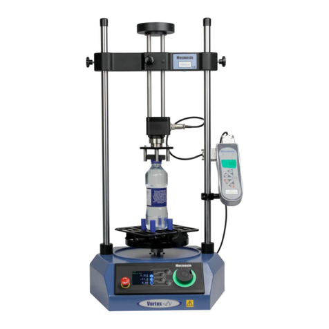
Mecmesin Vortex-dV 1.5 N.m User manual
Mecmesin

Mecmesin Vortex-dV 1.5 N.m User manual

Mecmesin MultiTest 1 User manual

Mecmesin

Mecmesin MultiTest 1 User manual

Mecmesin OmniTest-5.0 Specification sheet

Mecmesin

Mecmesin OmniTest-5.0 Specification sheet

Mecmesin CrimpTest-1 kN User manual

Mecmesin

Mecmesin CrimpTest-1 kN User manual

Mecmesin OmniTest-5.0 User manual

Mecmesin

Mecmesin OmniTest-5.0 User manual

Mecmesin Vortex-dV User manual

Mecmesin

Mecmesin Vortex-dV User manual
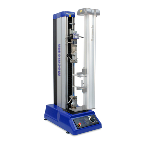
Mecmesin Orbis User manual

Mecmesin

Mecmesin Orbis User manual
Mecmesin Multitest 0.5d Installation and operating manual

Mecmesin

Mecmesin Multitest 0.5d Installation and operating manual

Mecmesin MultiTest 0.5-dV Installation and operating manual

Mecmesin

Mecmesin MultiTest 0.5-dV Installation and operating manual

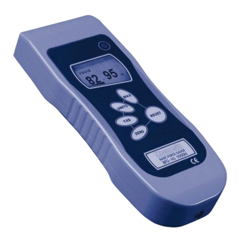
Mecmesin Basic Force Gauge-HS Mk3 User manual
Mecmesin

Mecmesin Basic Force Gauge-HS Mk3 User manual

Popular Test Equipment manuals by other brands

Agilent Technologies 3000 Series User's and service guide

Agilent Technologies

Agilent Technologies 3000 Series User's and service guide

Gemini Tinytag TGE-0003 Technical manual

Gemini

Gemini Tinytag TGE-0003 Technical manual

Apera Instruments PH60S user manual

Apera Instruments

Apera Instruments PH60S user manual

Hameg HM 303-5 Service manual

Hameg

Hameg HM 303-5 Service manual

TAKAYA APT-9411 Series Service manual

TAKAYA

TAKAYA APT-9411 Series Service manual

Omicron CPC 100 Reference manual

Omicron

Omicron CPC 100 Reference manual

Controls SPEEDLOADER 34-V1082 instruction manual

Controls

Controls SPEEDLOADER 34-V1082 instruction manual

ALMO MN103 user manual

ALMO

ALMO MN103 user manual

Sensidyne Go-Cal user manual

Sensidyne

Sensidyne Go-Cal user manual

VOP LC-CAST 600 user manual

VOP

VOP LC-CAST 600 user manual

Solar BA327 user manual

Solar

Solar BA327 user manual

SENSIT Technologies SMART-CAL Operation manual

SENSIT Technologies

SENSIT Technologies SMART-CAL Operation manual

Hioki BT3563A instruction manual

Hioki

Hioki BT3563A instruction manual

Tempo Fitness 24A STATION MASTER PRO instruction manual

Tempo Fitness

Tempo Fitness 24A STATION MASTER PRO instruction manual

Jinhan JDS6052S user manual

Jinhan

Jinhan JDS6052S user manual

Wildlife Acoustics Ultrasonic Calibrator quick start guide

Wildlife Acoustics

Wildlife Acoustics Ultrasonic Calibrator quick start guide

Tektronix 2245A Operator's manual

Tektronix

Tektronix 2245A Operator's manual

VACUTEC Leakfinder 625-WV609 instruction manual

VACUTEC

VACUTEC Leakfinder 625-WV609 instruction manual

manuals.online logo
manuals.online logoBrands
  • About & Mission
  • Contact us
  • Privacy Policy
  • Terms and Conditions

Copyright 2025 Manuals.Online. All Rights Reserved.