Superchips Flashcal User manual

STORAGE AND MAINTENANCE ............................................................................................... 3
BEFORE YOU BEGIN ................................................................................................................. 4
LIST OF COMPONENTS.....................................................................................................................4
BUTTON FUNCTIONALITY ................................................................................................................4
BASIC MENU LAYOUT............................................................................................................... 5
DOWNLOAD IGNITION UPDATER TOOL.................................................................................. 6
PRODUCT UPDATES USING IGNITION .................................................................................... 8
OPTIONS ................................................................................................................................... 10
OPTIONS EXPLAINED.............................................................................................................. 11
READ DTC................................................................................................................................. 12
CLEAR DTC .............................................................................................................................. 13
VIEWING GAUGES ................................................................................................................... 14
DATA LOGGING ....................................................................................................................... 15
DATA LOGGING RETRIEVAL .................................................................................................. 16
BATTERY VOLTAGE ................................................................................................................ 17
VEHICLE INFO .......................................................................................................................... 18
DEVICE INFO ............................................................................................................................ 19
SAFETY WARNING & CAUTION.............................................................................................. 20
SAFETY GUIDELINES .............................................................................................................. 21
LIMITED 1 YEAR WARRANTY ................................................................................................. 22
2
TABLE OF CONTENTS

3
NOTICE
It is NOT recommended to store your programmer in your vehicle in
extreme heat, direct sunlight or extreme cold (temperatures near or
below freezing). These conditions can cause malfunction or damage
to the programmer.
TIP: When you are not using your device,
place it in its protective bag. This will keep the
display from getting scratched.
TIP: Prior to using your device after a long period of non-use, use Ignition to update. This will ensure
that your device is up-to-date and contains all of the latest les and functionality.
Ignition
STORAGE AND MAINTENANCE
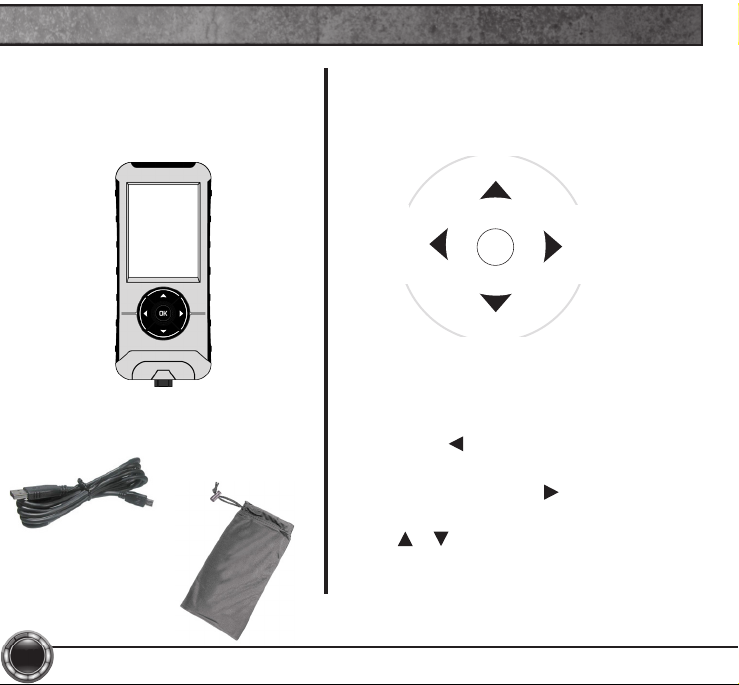
LIST OF COMPONENTS
DISPLAY DEVICE
BUTTON FUNCTIONALITY
NAVIGATING TIPS:
• To move back to the previous menu,
press the button.
• To move forward to the next menu, you
can press either OK or button to
enter the highlighted option.
• The & buttons are used to select
menu options, as well as adjust values for
certain features.
Up_Increase
Right
Next
Forward
Left
Back
Exit
Down_Decrease
OK
USB CABLE PROTECTIVE
BAG
4
BEFORE YOU BEGIN
5
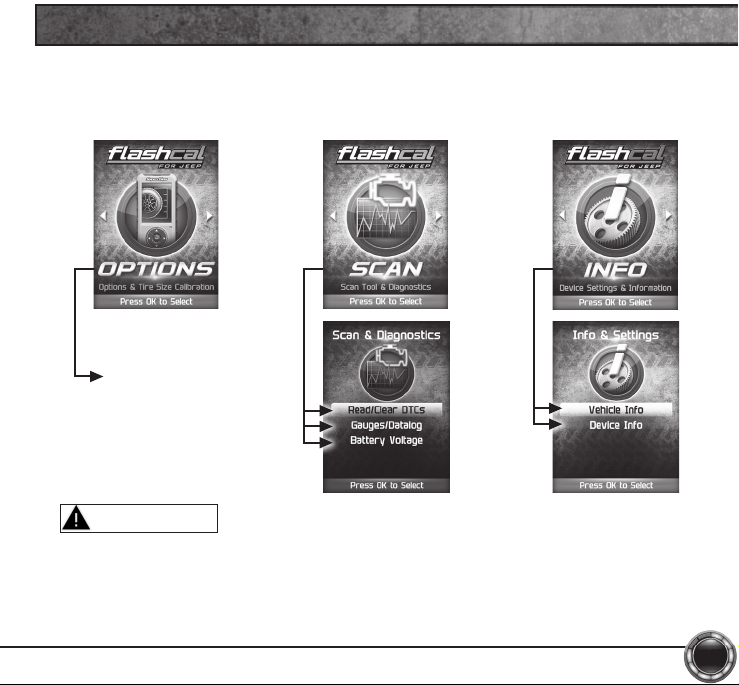
Some of the menu options or features displayed in this manual are
vehicle specic, and may not be available for your make and model.
Adjustable Options
BASIC MENU LAYOUT
Misapplication or misuse of this product could lead to a serious or
fatal accident. Comply with all safety information in this manual, and
your vehicle owners manual. Follow safety, installation and operating
instructions in this User Manual to assure proper use.
WARNING
1 Go to: www.superchips.com
2 Click the UPDATES tab located at the top of the page.
3 Click the Download button to download Ignition.
4 Click the Run button on the pop-up menu.
5 Read and click the box to accept the license agreement terms.
6 Click the Install Button, then the Close button once the download is complete.
7 Double-click the Ignition desktop icon.
8 Fill out the registration form.
9 Refer to the next section for performing product update.
6
DOWNLOAD IGNITION UPDATER TOOL
TIP: Use a wired internet connection vs. wireless, air card, or satellite connections. This will minimize
potential connection issues that may affect the update process.

7
1
2
3
4
5
6
Ignition

1 Double-click the Ignition Icon located on your computer’s desktop.
2 Connect your device to the computer using the supplied USB cable.
(Ignition will automatically search for updates related to your device.)
3 Click the Update button.
(The update process will start and nish automatically. Once the update is
complete, you may be directed to the Online Store. To further update your
device using the online store, refer to the following steps.)
4 Click on any or all of the available options.
(A check mark will appear in the upper right corner.)
5 Click the Purchase button.
6 If required, read and Accept the disclaimer.
7 Fill in the required information and click Go to Review.
(Here you can check the information you lled in before submitting the order.)
8 Click the Place Order button to complete your order.
9 If a purchase was made, follow steps 1-3 above to complete the update.
8
PRODUCT UPDATES USING IGNITION

1
2
4
5
3
6
7
8
NOTICE
Do not unplug the USB while the device
is being updated. Once the update is
complete, you will be informed that it is
safe to disconnect.
9
Ignition

10
STEP 1 - Enter
the Options Menu
by pressing ok.
STEP 2 - Follow
the on-screen
instructions.
STEP 3 - Select
an option from
the list provided.
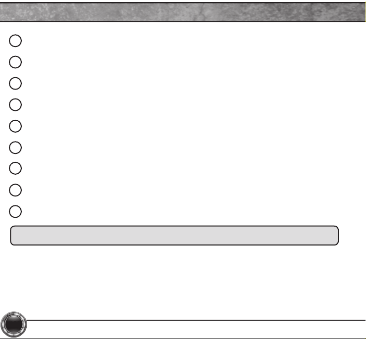
OPTIONS
Quick Options
Axle Lock
Engine Idle
Lamp Delay
Run Lights
Acc Delay
Lane Change
Lamp Flash
Horn Chirp
Fog Lights
Exit
CAUTION
WARNING
Do not make adjustments to your vehicle while parked in unsafe locations
including heavy trafc or places without cell phone service.
STEP 4 - Modify
each setting
according to your
specic needs.
These options allow to you quickly adjust the settings for the available
features.
NOTE: Not all features are available on every make, model, and engine.
Do not remove or bump the OBD-II connector while changing Quick option
settings. If you do, the vehicle may not start.
Daytime Run Lamps
High Beams
Low Beams
Turn Signals
Fog Lights
European Lights
No Running Lights
Table of contents
Other Superchips Test Equipment manuals


