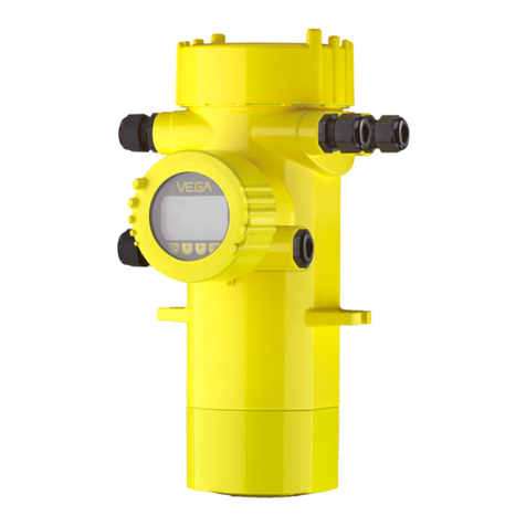
Vega POINTRAC 31 User manual

Operating Instructions
POINTRAC 31
Foundation Fieldbus
Document ID:
41779
Radiation-based

Contents
1About this document
1.1Function.................................. 4
1.2Target group .............................. 4
1.3Symbolism used............................ 4
2For your safety
2.1Authorised personnel ........................ 5
2.2Appropriate use ............................ 5
2.3Warning about misuse ....................... 5
2.4General safety instructions . . . . . . . . . . . . . . . . . . . . 5
2.5CE conformity ............................. 6
2.6NAMUR recommendations . . . . . . . . . . . . . . . . . . . . 6
2.7Environmental instructions..................... 6
3Product description
3.1Structure ................................. 7
3.2Principle of operation ........................ 8
3.3Packaging,transport and storage ............... 8
3.4Accessories and replacement parts . . . . . . . . . . . . . . 9
3.5Corresponding source container . . . . . . . . . . . . . . . . 10
4Mounting
4.1General instructions ......................... 12
4.2Instructions for installation ..................... 12
5Connecting to power supply
5.1Preparing the connection ..................... 16
5.2Connection................................ 19
6Set up with the indicating and adjustment module
6.1Insert indicating and adjustment module. . . . . . . . . . . 22
6.2Adjustment system .......................... 23
6.3Parameter adjustment........................ 24
6.4Saving the parameter adjustment data . . . . . . . . . . . . 33
7Setup with PACTware
7.1Connect the PC ............................ 34
7.2Parameter adjustment with PACTware . . . . . . . . . . . . 34
7.3Saving the parameter adjustment data . . . . . . . . . . . . 35
8Set up with other systems
8.1DD adjustment programs ..................... 36
8.2Communicator 375,475 . . . . . . . . . . . . . . . . . . . . . . 36
9Diagnosis and service
9.1Maintenance .............................. 37
9.2Status messages ........................... 37
9.3Remove interferences ........................ 41
2POINTRAC 31 •Foundation Fieldbus
Contents
41779-EN-120329

9.4Exchanging the electronics module . . . . . . . . . . . . . . 42
9.5Software update ............................ 42
9.6How to proceed in case of repair................ 43
10 Dismounting
10.1Dismounting steps .......................... 44
10.2Disposal ................................. 44
11 Supplement
11.1Technical data ............................. 45
11.2Supplementary information Foundation Fieldbus . . . . . 50
Safety instructions for Ex areas
Please note the Ex-specific safety information for installation and
operation in Ex areas.These safety instructions are part of the
operating instructions manual and come with the Ex-approved
instruments.
Editing status:2012-03-20
POINTRAC 31 •Foundation Fieldbus 3
Contents
41779-EN-120329

1About this document
1.1Function
This operating instructions manual provides all the information you
need for mounting,connection and setup as well as important
instructions for maintenance and fault rectification.Please read this
information before putting the instrument into operation and keep this
manual accessible in the immediate vicinity of the device.
1.2Target group
This operating instructions manual is directed to trained qualified
personnel.The contents of this manual should be made available to
these personnel and put into practice by them.
1.3Symbolism used
Information,tip,note
This symbol indicates helpful additional information.
Caution:If this warning is ignored,faults or malfunctions can
result.
Warning:If this warning is ignored,injury to persons and/or serious
damage to the instrument can result.
Danger:If this warning is ignored,serious injury to persons and/or
destruction of the instrument can result.
Ex applications
This symbol indicates special instructions for Ex applications.
lList
The dot set in front indicates a list with no implied sequence.
àAction
This arrow indicates a single action.
1Sequence
Numbers set in front indicate successive steps in a procedure.
4POINTRAC 31 •Foundation Fieldbus
1About this document
41779-EN-120329

2For your safety
2.1Authorised personnel
All operations described in this operating instructions manual must be
carried out only by trained specialist personnel authorised by the plant
operator.
During work on and with the device the required personal protective
equipment must always be worn.
2.2Appropriate use
The POINTRAC 31 is a sensor for level detection.
You can find detailed information on the application range in chapter
"Product description".
Operational reliability is ensured only if the instrument is properly used
according to the specifications in the operating instructions manual as
well as possible supplementary instructions.
2.3Warning about misuse
Inappropriate or incorrect use of the instrument can give rise to
application-specific hazards,e.g.vessel overfill or damage to system
components through incorrect mounting or adjustment.
2.4General safety instructions
This is a state-of-the-art instrument complying with all prevailing
regulations and guidelines.The instrument must only be operated in a
technically flawless and reliable condition.The operator is responsible
for the trouble-free operation of the instrument.
During the entire duration of use,the user is obliged to determine the
compliance of the necessary occupational safety measures with the
current valid rules and regulations and also take note of new
regulations.
The safety instructions in this operating instructions manual,the
national installation standards as well as the valid safety regulations
and accident prevention rules must be observed by the user.
For safety and warranty reasons,any invasive work on the device
beyond that described in the operating instructions manual may be
carried out only by personnel authorised by the manufacturer.Arbitrary
conversions or modifications are explicitly forbidden.
The safety approval markings and safety tips on the device must also
be observed.
POINTRAC 31 •Foundation Fieldbus 5
2For your safety
41779-EN-120329

2.5CE conformity
The device fulfills the legal requirements of the applicable EC
guidelines.By affixing the CE marking,VEGA confirms successful
testing of the product.
Only with class Ainstruments:
The device is a class Ainstrument designed for use in an industrial
environment.When used in a different environment,e.g., in a living
area,the electromagnetic compatibility must be ensured by the user.If
necessary,suitable screening measures against conducted and
emitted disturbances must be taken.
You can find the conformity certificate in the download section under
www.vega.com.
2.6NAMUR recommendations
NAMUR is the automation technology user association in the process
industry in Germany.The published NAMUR recommendations are
accepted as the standard in field instrumentation.
The device fulfills the requirements of the following NAMUR
recommendations:
lNE 21 –Electromagnetic compatibility of equipment
lNE 43 –Signal level for malfunction information from measuring
transducers
lNE 53 –Compatibility of field devices and indicating/adjustment
components
lNE 107 -Self-monitoring and diagnosis of field devices
For further information see www.namur.de.
2.7Environmental instructions
Protection of the environment is one of our most important duties.That
is why we have introduced an environment management system with
the goal of continuously improving company environmental protection.
The environment management system is certified according to DIN
EN ISO 14001.
Please help us fulfil this obligation by observing the environmental
instructions in this manual:
lChapter "Packaging,transport and storage"
lChapter "Disposal"
6POINTRAC 31 •Foundation Fieldbus
2For your safety
41779-EN-120329

3Product description
3.1Structure
The type label contains the most important data for identification and
use of the instrument:
2
1
9
10
4
5
3
6
7
8
9
Fig.1:Structure of the type label (example)
1Instrument type
2Product code
3Electronics
4Protection rating
5Process and ambient temperature,process pressure
6Instrument length
7Hardware and software version
8Order number
9Serial number of the instrument
10 ID numbers,instrument documentation
With the serial number of the instrument on the type label you have
access to the following data on our homepage:
lArticle number of the instrument (HTML)
lDelivery date (HTML)
lOrder-specific instrument features (HTML)
lOperating instructions at the time of shipment (PDF)
lOrder-specific sensor data for an electronics exchange (XML)
lTest certificate "Measuring Accuracy"(PDF)
Go to www.vega.com,"Service" "VEGA Tools"and "serial number
search".
This operating instructions manual applies to the following instrument
versions:
lHardware from 1.0.4
lSoftware from 1.5.0
lModification status electronics from -01
Type label
Serial number
Scope of the operating
instructions manual
POINTRAC 31 •Foundation Fieldbus 7
3Product description
41779-EN-120329

The instrument is available in different electronics versions.Each
version can be identified via the product code on the type label as well
as on the electronics:
lStandard electronics type PROTRACF.-XX
The scope of delivery encompasses:
lRadiation-based sensor
lMounting accessory
lDocumentation
-this operating instructions manual
-Safety Manual (SIL)POINTRAC 31 (optional)
-Operating instructions manual "Indicating and adjustment
module"(optional)
-Ex-specific"Safety instructions"(with Ex versions)
-if necessary,further certificates
3.2Principle of operation
The instrument is suitable for applications in liquids and bulk solids in
vessels under difficult process conditions.There are application
possibilities in nearly all areas of industry.
The limit level is detected contactlessly through the vessel wall.
Neither a process fitting nor a vessel opening is required.The
instrument is thus ideal for retrofitting.
In radiation-based measurement,aCaesium-137 or Cobalt-60 isotope
emits focussed gamma rays that are attenuated when penetrating the
vessel wall and the medium.The PVT detector on the opposite side of
the tank receives the radiation.When the intensity of the radiation
drops below a defined value,e.g.due to damping,then the
POINTRAC 31 switches.The measuring principle has proven itself
well under extreme conditions because it measures contactlessly from
outside through the vessel wall.The measuring system ensures
maximum safety,reliability and plant availability independent of the
medium and its properties.
3.3Packaging,transport and storage
Your instrument was protected by packaging during transport.Its
capacity to handle normal loads during transport is assured by a test
according to DIN EN 24180.
The packaging of standard instruments consists of environment-
friendly,recyclable cardboard.For special versions,PE foam or PE foil
is also used.Dispose of the packaging material via specialised
recycling companies.
Electronics versions
Scope of delivery
Application range
Functional principle
Packaging
8POINTRAC 31 •Foundation Fieldbus
3Product description
41779-EN-120329


Transport must be carried out under consideration of the notes on the
transport packaging.Nonobservance of these instructions can cause
damage to the device.
The delivery must be checked for completeness and possible transit
damage immediately at receipt.Ascertained transit damage or
concealed defects must be appropriately dealt with.
Up to the time of installation,the packages must be left closed and
stored according to the orientation and storage markings on the
outside.
Unless otherwise indicated,the packages must be stored only under
the following conditions:
lNot in the open
lDry and dust free
lNot exposed to corrosive media
lProtected against solar radiation
lAvoiding mechanical shock and vibration
lStorage and transport temperature see chapter "Supplement -
Technical data -Ambient conditions"
lRelative humidity 20 …85 %
3.4Accessories and replacement parts
The indicating and adjustment module PLICSCOM is used for
measured value indication,adjustment and diagnosis.It can be
inserted into the sensor and removed at any time.
You can find further information in the operating instructions "Indicating
and adjustment module PLICSCOM"(Document-ID 27835).
The interface adapter VEGACONNECT enables the connection of
communication-capable instruments to the USB interface of a PC.For
parameter adjustment of these instruments,an adjustment software
such as PACTware with VEGA-DTM is required.
You can find further information in the operating instructions "Interface
adapter VEGACONNECT"(Document-ID 32628).
VEGADIS 61 is an external indicating and adjustment unit for sensors
with single chamber housing and Ex-d double chamber housing.
It is suitable for measured value indication and adjustment of plics
®
sensors and is connected to the sensor with a four-wire,screened
standard cable up to 50 m long.
You can find further information in the operating instructions
"VEGADIS 61"(Document-ID 27720).
Transport
Transport inspection
Storage
Storage and transport
temperature
Indicating and adjust-
ment module
Interface adapter
External indicating and
adjustment unit
POINTRAC 31 •Foundation Fieldbus 9
3Product description
41779-EN-120329

The electronics module PROTRACH series 30 is a replacement part
for radiation-based sensors POINTRAC 31.
You can find further information in the operating instructions
"Electronics modulePOINTRAC 31"(Document-ID 40104).
3.5Corresponding source container
Aradioactive isotope in a suitable source holder is the prerequisite for
a radiation-based measurement setup.
The handling of radioactive material is regulated by law.The radiation
protection rules of the country in which the system is operated are
relevant for operation.
InGermany,for example,the current radiation protection ordinance
(StrlSchV)based on the Atomic Energy Law (AtG)applies.
The following points are important for measurement with radiation-
based methods:
Ahandling permit is required for operation of a system using gamma
rays.This permit is issued by the respective government office or the
responsible authority (in Germany,for example,offices for environ-
mental protection,trade supervisory boards,etc.)
You can find further instructions in the operating instructions manual of
the source container.
When handling radioactive sources,unnecessary radiation exposure
must be avoided.An unavoidable radiation exposure must be kept as
low as possible.Take note of the following three important measures:
1 2 3
Fig.2:Measures for protection against radioactive radiation
1Shielding
2Time
3Distance
Electronics module
Handling permit
General instructions for
radiation protection
10 POINTRAC 31 •Foundation Fieldbus
3Product description
41779-EN-120329
Shielding -Provide good shielding between the radioactive source
and yourself as well as all other persons.Special source containers (e.
g.VEGASOURCE)as well as all materials with high density (e.g.lead,
iron,concrete,etc.) provide effective shielding.
Time -Stay as short a time as possible in radiation exposed areas.
Source -Your distance to the source should be as large as possible.
The local dose rate of the radiation decreases in proportion to the
square of the distance to the radiation source.
The plant operator must appoint a radiation safety officer with the
necessary expert knowledge.He is responsible that the radiation
protection ordinance is maintained and that all radiation protection
measures are implemented.
Control areas are areas in which the local dose rate exceeds a certain
value.Only persons who undergo official dose monitoring are allowed
into these control areas.You can find the respectively valid limit values
for control areas in the guideline of the respective authority (in
Germany,for example,the radiation protection ordinance).
We are at your disposal for further information concerning radiation
protection and regulations in other countries.
Radiation safety officer
Control area
POINTRAC 31 •Foundation Fieldbus 11
3Product description
41779-EN-120329
4Mounting
4.1General instructions
The source container is part of the measuring system.In case the
source container is already equipped with an active isotope,the
source container must be locked before mounting.
Danger:
Before mounting make sure that the source is reliably switched off.
Use a padlock to secure the source container in the switched-off
condition and prevent it from being inadvertently switched on.
Use the recommended cables (see chapter "Connecting to power
supply")and tighten the cable gland.
You can give your instrument additional protection against moisture
penetration by leading the connection cable downward in front of the
cable entry.Rain and condensation water can thus drain off.This
applies mainly to outdoor mounting as well as installation in areas
where high humidity is expected (e.g.through cleaning processes)or
on cooled or heated vessels.
Make sure that all parts of the instrument exposed to the process,in
particular the active measuring component,process seal and process
fitting,are suitable for the existing process conditions.These include
above all the process pressure,process temperature as well as the
chemical properties of the medium.
You can find the specifications in chapter "Technical data"and on the
type label.
In the case of instrument housings with self-sealing NPT threads,it is
not possible to have the cable glands screwed in at the factory.The
openings for the cable glands are therefore covered with red protective
caps as transport protection.
Prior to setup you have to replace these protective caps with approved
cable glands or close the openings with suitable blind plugs.
The suitable cable glands and blind plugs come with the instrument.
4.2Instructions for installation
Note:
During the planning stage,our specialists will analyse the conditions of
the measuring point and dimension the source (isotope)accordingly.
You get a "Source Sizing"document specifying the required isotope
strength and containing all relevant mounting information for your
measuring point.
Switch offsource
Moisture
Suitability for the pro-
cess conditions
Protective caps
Mounting position
12 POINTRAC 31 •Foundation Fieldbus
4Mounting
41779-EN-120329

You must follow the instructions of this "Source Sizing"document in
addition to the following mounting instructions.
The following mounting information is applicable as long as there is
nothing else specified in the "Source Sizing"document.
2
1
Fig.3:Mounting position -level detection
1Mounting vertically
2Mounting horizontally,at right angles to container
You can find information on protective barriers and the mounting of the
corresponding source container in the operating instructions manual of
the source container,e.g.VEGASOURCE.
For level detection,the sensor is generally mounted horizontally at the
height of the requested limit level.Make sure that there are no struts or
reinforcements at this position in the vessel.
Direct the exit beam of the source container exactly towards the
measuring range of POINTRAC 31.
Fasten the sensor in such a way that it cannot fall out of the holder.If
necessary,provide the sensor with a support from below.
Mount the source container and POINTRAC 31 as close as possible to
the vessel.If there are gaps,secure the area with a safety fence and
protective grating so that no one can reach into the dangerous area.
POINTRAC 31 •Foundation Fieldbus 13
4Mounting
41779-EN-120329

Level detection -max.detection
The POINTRAC 31 is suitable for level detection in liquids or bulk
solids.It is mounted at the height of the requested switching point.
Fig.4:POINTRAC 31 as max.level detection (uncovered)
Level detection -min.detection
Fig.5:POINTRAC 31 as min.level detection (covered)
Sensor orientation
Bulk solids with low
density
14 POINTRAC 31 •Foundation Fieldbus
4Mounting
41779-EN-120329

Fig.6:POINTRAC 31 as level detection (top view)
POINTRAC 31 lends itself well for level detection of bulk solids with
low density.Mount the instrument horizontally at the height of the
requested switching point.
Mount the source container VEGASOURCE displaced by 90°in order
to get the widest possible radiation angle.
When the sensor is covered by the medium,the radiation damping is
considerably stronger -hence,the switching point is all the more
reliable.
If the max.ambient temperature is exceeded,you must take suitable
measures to protect the instrument against overheating.
You can protect the instrument by providing a suitable insulation
against the heat or mounting the instrument further away from the heat
source.
Make sure these measures are taken into account already in the
planning stage.If you want to carry out such measures later on,
contact our specialists to ensure that the accuracy of the application is
not impaired.
If these measures are not sufficient to maintain the max.ambient
temperature,you could consider using the water cooling system we
offer for POINTRAC 31.
The water cooling must also be included in the calculations for the
measuring point.Contact our specialists regarding the dimensioning of
the water cooling.
Protection against heat
POINTRAC 31 •Foundation Fieldbus 15
4Mounting
41779-EN-120329

5Connecting to power supply
5.1Preparing the connection
Always keep in mind the following safety instructions:
lConnect only in the complete absence of line voltage
lIf voltage surges are expected,install overvoltage arresters
The instrument requires a operating voltage of 9…32 V DC.
Operating voltage and the digital bus signal are carried on the same
two-wire connection cable.Power is supplied via the H1power supply.
Connection is carried out with screened cable according to Fieldbus
specification.
Use cable with round cross-section.Acable outer diameter of 5…9mm
(0.2…0.35 in)ensures the seal effect of the cable gland.If you are
using cable with a different diameter or cross-section,exchange the
seal or use a suitable cable gland.
Make sure that the entire installation is carried out according to the
Fieldbus specification.In particular,make sure that the bus is
terminated with suitable terminating resistors.
With plastic housing,the NPT cable gland or the Conduit steel tube
must be screwed without grease into the threaded insert.
Max.torque for all housings see chapter "Technical data"
In the case of instrument housings with self-sealing NPT threads,it is
generally not possible to have the cable glands screwed in at the
factory.The openings for the cable glands are therefore covered with
red protective caps as transport protection.
You have to replace these protective caps with approved cable glands
before setup or cover them with suitable filler plugs.Unused cable
glands do not provide sufficient protection against moisture and must
be replaced with filler plugs.
The suitable cable glands and blind plugs come with the instrument.
Make sure that the cable screening and ground is executed according
to the Fielbus specification.If electromagnetic interference is expected
which is above the test values of EN 61326-1for industrial areas,we
recommend to connect the cable screen on both ends to ground
potential.
With systems with potential equalisation,connect the cable screen
directly to ground potential at the power supply unit,in the connection
box and at the sensor.The screen in the sensor must be connected
directly to the internal ground terminal.The ground terminal outside on
the housing must be connected to the potential equalisation (low
impedance).
Safety instructions
Voltage supply
Connection cable
Cable gland ½NPT
Cable screening and
grounding
16 POINTRAC 31 •Foundation Fieldbus
5Connecting to power supply
41779-EN-120329

In systems without potential equalisation with cable screening on both
sides,connect the cable screen directly to ground potential at the
power supply unit and at the sensor.In the connection box or T-
distributor,the screen of the short stub to the sensor must not be
connected to ground potential or to another cable screen.The cable
screens to the power supply unit and to the next distributor must be
connected to each other and also connected to ground potential via a
ceramic capacitor (e.g.1nF,1500 V). Low-frequency potential
equalisation currents are thus suppressed,but the protective effect
against high frequency interference signals remains.
The voltage supply and signal output are connected via the spring-
loaded terminals in the housing.
The connection to the indicating and adjustment module or to the
interface adapter is carried out via contact pins in the housing.
Proceed as follows:
The procedure applies to instruments without explosion protection.
1Unscrew the big housing cover
2Loosen compression nut of the cable entry
3Remove approx.10 cm (4in)of the cable mantle,strip approx.
1cm (0.4in)of insulation from the ends of the individual wires
Connection technology
Connection procedure
POINTRAC 31 •Foundation Fieldbus 17
5Connecting to power supply
41779-EN-120329

4Insert the cable into the sensor through the cable entry
1
Fig.7:Connection steps 4and 5
1Locking of the terminal blocks
5Insert a small slotted screwdriver firmly into the rectangular lock
openings of the respective connection terminal
6Insert the wire ends into the round openings of the terminals
according to the wiring plan
Information:
Solid cores as well as flexible cores with cable end sleeves are
inserted directly into the terminal openings.In case of flexible cores
without end sleeves,press the rectangular lock opening with a small
screwdriver;the terminal opening is freed.When the screwdriver is
released,the terminal opening closes again.
7Check the hold of the wires in the terminals by lightly pulling on
them
To loosen a line,insert a small slotted screwdriver firmly into the
rectangular locking opening according to the illustration
8Connect the screen to the internal ground terminal,connect the
outer ground terminal to potential equalisation
9Tighten the compression nut of the cable entry.The seal ring must
completely encircle the cable
10 Screw the housing cover back on
18 POINTRAC 31 •Foundation Fieldbus
5Connecting to power supply
41779-EN-120329

The electrical connection is finished.
Information:
The terminal blocks are pluggable and can be detached from the
electronics.For this purpose loosen the two lateral locking levers of
the terminal block with a small screwdriver.When loosening the
locking,the terminal block is automatically squeezed out.It must snap
in place when re-inserted.
5.2Connection
Non-Ex instruments and instruments with pressure-tight encap-
sulation (Ex-d approval)
1
1
2 4
/L
/N
PE
5 6
22
11
12
2122 1920 18 17 14 1316 15 12
2
6
1
43
5
7
8
9
10
Fig.8:Electronics and connection compartment with non-Ex instruments and
instruments with Ex-d approval
1Voltage supply
2Relay output
3Signal output FF bus
4Signal input 4…20 mA(active sensor)
5Switching input for NPN transistor
6Switching input floating
7Transistor output
8Interface for sensor-sensor communication
9Simulation switch (1=simulation on)
10 Setting the bus address for sensor-sensor communication (MGC)1)
1)MGC =Multi Gauge Connection
Electronics and
connection
compartment -
Non-Ex instru-
ments,Ex-d ap-
proval
POINTRAC 31 •Foundation Fieldbus 19
5Connecting to power supply
41779-EN-120329

5 6 7 8
2
1
Fig.9:Adjustment and connection compartment with non-Ex instruments and
instruments with Ex-d approval
1Terminals for the external indicating and adjustment unit
2Contact pins for the indicating and adjustment module or interface adapter
Instruments with intrinsically safe current output (Ex-ia appro-
val)
You can find detailed information on the explosion-protected versions
(Ex-ia,Ex-d)in the Ex-specific safety instructions.These safety
instructions are part of the scope of delivery and come with the Ex-
approved instruments.
Adjustment and connec-
tion compartment -Non-
Ex instruments,Ex-d
approval
20 POINTRAC 31 •Foundation Fieldbus
5Connecting to power supply
41779-EN-120329
Other manuals for POINTRAC 31
6
Table of contents
Other Vega Measuring Instrument manuals

Vega
Vega VEGACAL 65 User manual

Vega
Vega VEGASON 61 User manual

Vega
Vega VEGAFLEX 62 User manual

Vega
Vega VEGAFLEX 81 User manual

Vega
Vega VEGAPULS 66 User manual

Vega
Vega VEGACAP 65 User manual

Vega
Vega VEGABAR 17 User manual

Vega
Vega VEGABAR 17 User manual

Vega
Vega VEGACAP 67 User manual

Vega
Vega plicscom User manual

Vega
Vega VEGAPULS 63 User manual

Vega
Vega VEGADIS 61 User manual

Vega
Vega VEGAPULS 67 User manual

Vega
Vega VEGAMIP R61 User manual

Vega
Vega VEGAPULS WL 61 User manual

Vega
Vega VEGABAR 81 User manual

Vega
Vega VEGASON 62 User manual

Vega
Vega VEGACAL 66 User manual

Vega
Vega VEGAPULS 61 User manual

Vega
Vega VEGAMIP R62 User manual