Mecon mag-flux M1 User manual

Mecon GmbH Phone +49(0)241 41369 – 0
Fax +49(0)241 41369 – 40
Ziegler traße 10 – 16 www.mecon.de
cu tomer [email protected]
Page 1 / 35
D-52078 Aachen
Mecon 02/2010
Tran mitter mag-flux M1
Fig 1 Transmitter max-flux M1
__ Application domain
The mag-flux M1 is a microprocessor controlled and program-
mable transmitter that can be customized using control unit
(option). Although basic configuration settings such as trans-
mitter calibration are realized at the factory, other settings such
as those for measurement data processing, analysis, display and
output are user definable.
Measurement data from sensors of series mag-flux are processed
by the transmitter (hereinafter referred to as mag-flux M1). t
can be installed directly on the sensor (compact version) or be
mounted separately (remote version) and it is designed for flow
velocities up to 10 m/s.
A remote version is available for sensor mag-flux A, mag-flux S,
mag-flux F5 and also for probes mag-flux M S 1/D and mag-flux
M S 2/15.
A compact version is only available for sensor mag-flux A.
The transmitter mag-flux M1 is communication enabled and
supports optional the HART® protocol.
__ Special feature
• High-speed signal processing by 16-bit Microcontroller
• Easy multilingual menu navigation with a two-line display
(Option)
• Self-monitoring system
• nternal simulation for all output values
• Analog output (0/4-20 mA)
• Digital outputs (pulse, frequency, alarm, forward and
reverse flow, M N / MAX flow rate)
• User settings protected by user definable password
__ Introduction
I. Shipping, torage and product in pection
Shipping and storage
The device is to be safeguarded against dampness, dirt, impact
and damage.
Product inspection
Upon receipt of the product, check the contents of the box and
the product particulars against the information on the delivery
slip and order form so as to ensure that all ordered components
have been supplied. Notify us of any shipping damage
immediately upon receipt of the product. Any damage claim
received at a later time will not be honored.
II. Warranty
Your flowmeter was manufactured in accordance with the highest
quality standards and was thoroughly tested prior to shipment.
However, in the event any problem arises with your device, we
will be happy to resolve the problem for you as quickly as
possible under the terms of the warranty which can be found in
the terms and conditions of delivery. Your warranty will only be
honored if the device was installed and operated in accordance
with the instructions for your device. Any mounting,
commissioning and/or maintenance work is to be carried out by
qualified and authorized technicians only.
III. Repair
t is important that you do the following before shipping your
flowmeter to MECON GmbH for repair:
• Enclose a description of the problem with your device.
Describe in as much detail as possible the application and
the physical and chemical properties of the fluid.
• Remove any residues from the device and be sure to clean
the seal grooves and recesses thoroughly. This is
particularly important if the fluid is corrosive, toxic,
carcinogenic, radioactive or otherwise hazardous.
• The operator is liable for any substance removal or personal
damage costs arising from inadequate cleaning of a device
that is sent for repair.
IV. U ing HART® hand-held terminal
For information regarding operation of the transmitter using the
HART hand-held terminal, see “Operation of the mag-flux M1
transmitter using the HART hand-held terminal.”
__ Step prior to operation
t is essential that you read these operating
instructions before installing and operating
the device. The device is to be installed and
serviced by a qualified technician only. The
mag-flux M1 transmitter is to be used exclu-
sively to measure volume flow of liquids in
conjunction with a sensor of series mag-flux.
Downloading of the present document from our web site
www.mecon.de and printing out this document is allowed only for
purposes of using our flowmeters. All rights reserved. No instruc-
tions, wiring diagrams, and/or supplied software, or any portion
thereof, may be produced, stored, in a retrieval system or
transmitted by any means, electronic, mechanical, photocopying

Mecon GmbH
Phone +49(0)241 41369 – 0 Fax +49(0)241 41369 – 40
Page 2 / 35
Ziegler traße 10 – 16
Mecon 02/2010 D-52078 Aachen
Tran mitter mag
-
flux M1
or otherwise, without the prior written permission of MECON
GmbH.
Although the materials in the present document were prepared
with extreme care, errors cannot be ruled out. Hence, neither the
company, the programmer nor the author can be held legally or
otherwise responsible for any erroneous information and/or any
loss or damage arising from the use of the information enclosed.
MECON GmbH extends no express or implied warranty in regard
to the applicability of the present document for any purpose
other than that described.
We try hard to optimize and improve the products and parti-
cularly we appreciate any suggestions for improvement made by
our customers. f you have any recommendation for improving
our products please send your suggestions to the following
address:
Mecon GmbH
Dept. Development
Headword: mag-flux M1
Ziegler traße 10-16
D-52078 Aachen
or:
via fax: +49 (0)241 – 41369 – 40
via email: cu tomer ervice@mecon.de
We reserve the right to change the technical data in
this manual in the light of any technical progress that
might be made. For updates regarding this product,
visit our website at www.mecon.de, where you will also
find contact information for the MECON distributor
nearest to you. For information regarding our own sales
In tallation and ervicing
The devices described in this manual are to be installed and
serviced only by qualified technical personnel such as a qualified
MECON GmbH electronics engineer or service technician.
Caution
Before servicing the device, it must be
completely switched off, and disconnected
from all peripheral devices. The technician
must also check to ensure that the device is
completely off-circuit. Only original replace-
ment parts are to be used.
MECON GmbH accepts no liability for any loss or damage of
any kind arising from improper operation of any product,
improper handling or use of any replacement part, or from
external electrical or mechanical effects, overvoltage or
lightning. Any such improper operation, use or handling shall
automatically invalidate the warranty for the product
concerned.
n the case of a problem with your device, please contact us
using one of the following numbers:
Phone: +49 (0)241 - 41369 - 0
Fax: +49 (0)241 - 41369 - 40
Contact our customer service department if your device needs
repair or if you need assistance in diagnosing a problem with
your device
Safety advi ory for the u er
The present document includes all information you need for
proper operation of the product. The document is intended for
use by qualified personnel. This means personnel who are
qualified to operate the device described herein safely, including
• electronics engineers,
• electrical engineers
• service technicians
who are conversant with the safety regulations pertaining to the
use of electrical and automated technical devices and with the
applicable laws and regulations in their own country. The
personnel must be authorized by the facility operator to install,
commission and service the product described herein, and are to
read and understand the contents of the present operating
instructions before working with the device.
Hazard warning
The purpose of the hazard warnings listed below is to ensure that
device operators and maintenance personnel are not injured and
that the flowmeter and any devices connected to it are not
damaged.
The safety advisories and hazard warnings in the present docu-
ment to avoid injury of placing operators and maintenance
personnel and to avoid material damage are prioritized using the
terms listed below, which are defined as follows
Danger
means that failure to take the prescribed precautions will re ult
in death, severe bodily injury, or substantial material damage!
Warning
means that failure to take the prescribed precautions could
re ult in death, severe bodily injury, or substantial material
damage!

Mecon GmbH Phone +49(0)241 41369 – 0
Fax +49(0)241 41369 – 40
Ziegler traße 10 – 16 www.mecon.de
cu tomer [email protected]
Page 3 / 35
D-52078 Aachen
Mecon 02/2010
Tran mitter mag-flux M1
Caution
means that failure to take the prescribed precautions could result
light severe bodily injury or material damage!
Note
means that the accompanying text includes important
information about the product, handling the product or about a
section of the documentation that is of particular importance.
Proper u e of the device
Caution
The operator is responsible for ensuring that
the material used in the sensor and housing is
suitable and that such material meets the
requirements for the fluid being used and the
ambient site conditions. The manufacturer
accepts no responsibility in regard to such
material and housing.
Caution
n order for the device to perform correctly
and safely, it must be shipped, stored, set up,
mounted operated and maintained properly.
Return for ervicing or calibration
Before returning your flowmeter for servicing or calibration,
make sure it is completely clean. Any residues of substances that
could be hazardous to the environment or human health are to
be removed from all crevices, recesses, gaskets, and cavities of
the housing before the device is shipped!
Caution
The operator is liable for any loss or damage
of any kind, including personal injury, decon-
tamination measures, removal operations and
the like that are attributable to inadequate
cleaning of the device.
Any device returned for ervicing i to be
accompanied by a certificate a pecified
in „Product return form”!
The device is to be accompanied by a document describing the
problem. Please also quote the name of a contact person. This
will help to repair your device as expeditiously as possible and
therefore minimize the cost of repairing it.
Replacement of the tran mitter electronic
Before replacing the transmitter electronics, read the safety
instructions in Section „ Replacement of transmitter electronic”
on page 12.
Caution
Make sure that you obey the applicable stan-
dards and regulations pertaining to electrical
devices, device installation and process tech-
nology when replacing the transmitter elec-
tronics. The highly integrated electronic com-
ponents of the device are ESD sensitive.
Caution
The complete unit has to be replaced with all
of its printed boards (except for the memory
chip (DSM)). The specified precision and
interchangeability of the electronics are only
guaranteed if the complete insert is replaced.
__ Identifikation
Manufacturer Mecon GmbH
Zieglerstraße 10-16
D-52078 Aachen
Phone: +49 (0)241 4 13 69 – 0
Fax: +49 (0)241 4 13 69 – 40
nternet: http://www.mecon.de
email: customerserv[email protected]
Product type Transmitter for magnetic-inductive flow-
meters
Product name Transmitter Type mag-flux M1,
suitable for magnetic-inductive flowmeters
series mag-flux
Versions-Nr. 2.2 vom 08.01.2010
__ Commi ioning
In tallation of magnetic-inductive flowmeter
At the installation of the magnetic-inductive flow sensor the
instructions and notes of the assembly instructions and operating
manuals have to be followed. Also, abserve the regulations of
grounding, potential equalization and company-internal groun-
ding guidelines.
Potential
All outputs are electrically isolated from the auxiliary power, the
sensor circuit and from each other. The housing and the inter-
ference suppression filters of the power supply are connected to
PE.
The electrodes and measuring electronics are related to the
potential of the function earth FE of the sensor. FE is not
connected to PE, but may be connected with each other in the
sensor junction box. f the sensor is grounded by using ground
disks (earthing rings), these must in connected with the function
earth FE.
At a separate assembly of sensor and transmitter the outer
screen of the connecting cable is connected to the transmitter
housing and has PE potential. The inner screens of the electrode
line are connected to FE inside the junction box of the sensor and
to the mass (GND) of the transmitters electronic.
Details of all wirings, terminals and drawing can be found in the
chaper „Wiring diagrams” starting at page 9.
Cathodic protective unit
Using a cathodic protective unit to avoid corosion, which put a
voltage to the tube wall, it must be connected to terminal FE.
The transmitter boards, control panal and internal switches are
on the same potential as FE.
Mecon GmbH
Phone +49(0)241 41369 – 0 Fax +49(0)241 41369 – 40
Page 4 / 35
Ziegler traße 10 – 16
Mecon 02/2010 D-52078 Aachen
Tran mitter mag
-
flux M1
Caution
According to EN 50178:1997 all electrical
circuits with „protectiv safety isolation with-
out any protection against contacts” must
observe the following maximum voltages:
• Maximum AC voltage (Veff) 25 V
• Maximum DC voltage 60 V
It i trictly forbidden to connect FE to
any higher voltage!
Zero point calibration
n order to ensure that precise measurements are obtained, zero
point calibration is to be realized the first time the device is put
into operation and before any regular operations are carried out.
Zero point calibration is to be carried out using a fluid.
The zero calibration procedure is as follows:
• nstall the sensor as described in the manual.
• Check to ensure that the sensor is completely filled with
fluid and that there are no gas bubbles in the flow tubes.
• Set the process conditions such as pressure, temperature
and density.
• Close the cut-off device behind the sensor.
• Operate the transmitter in accordance with the instructions
in chapter „Zero point adjustment“ on page 11for the basic
version or chapter „Zero point calibration“ on page 20 for
the version with the control panel.
• Make sure that sufficient time is allowed for the electronics
to warm up.
• Allowing fluid to flow through the sensor during the zero
calibration procedure will skew the zero point and result in
false readings.
Startup condition
The device is not subject to specific startup conditions. However,
pressure surges should be avoided.
Commi ioning the mag-flux flow probe
n order to be able to calculate the volume flow when using the
mag-flux flow probes correctly from the measured flow velocity,
the installation requirements must be kept regarding position and
mounting depth correctly.
Transmitter settings must be made as specified in
chapter „Operating the mag-flux flow probes with
the mag-flux M1” on page 6 to ensure the correct
operation!
Particularly for existing installations after replace-
ments or modifications e.g. tubing diameter.
__ Arbeit wei e und Sy temaufbau
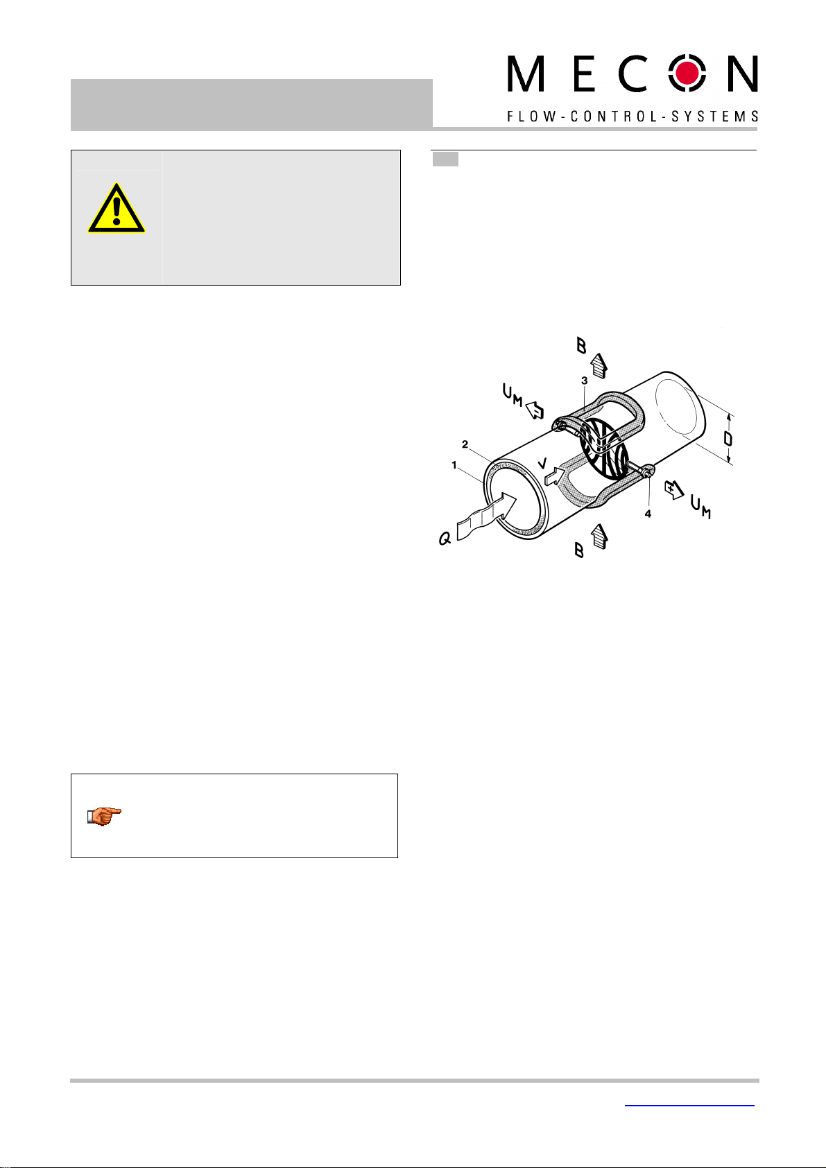
Mea uring principle
t was back in 1832 that Faraday suggested utilizing the principle
of electrodynamic induction for measuring flow velocities. His
experiments in the Thames, though unsuccessful due to
superimposed polarization effects, are nonetheless regarded as
the first experiment in the field of magnetic-inductive flow
measurement. According to Faraday’s law of electromagnetic
induction, an electrical field E is produced in a conductive liquid
moving through a magnetic field B at a velocity v in accordance
with the vector product E = [v x B].
Fig 2 Principle of the magnetic-inductive flow measurement
Through a meter tube provided with an insulating lining a liquid
flows at velocity v and a flow rate Q, producing a measuring-
circuit voltage Um at the two electrodes at right angles to the di-
rection of flow. The size of this measuring-circuit voltage is pro-
portional to the mean flow velocity and the volume flow rate.
Sy tem de ign
The meter consists of a mag-flux M1 transmitter and a sensor
e.g. mag-flux series. The device can be used to perform mea-
surements with any liquid, conductive media, providing that the
sensor’s material is suitable for the product being used.
The mag-flux M1 transmitter generates the inductive current
necessary for the magnetic field and preprocesses the induced
voltage at the electrodes.
Mecon GmbH Phone +49(0)241 41369 – 0
Fax +49(0)241 41369 – 40
Ziegler traße 10 – 16 www.mecon.de
cu tomer [email protected]
Page 5 / 35
D-52078 Aachen
Mecon 02/2010
Tran mitter mag-flux M1
Ba ic ver ion mag-flux M1
An analog 0/4...20 mA current output (active), a pulse or fre-
quency output and a status output are standard features of the
device.
A green LED is an operational readiness indicator, error are
indicated by a red light and reverse flow by a yellow light.
Fig 3 Basic version of the transmitter mag-flux M1
HART®-interface (Option)
An analog 0/4−20 mA output is a standard feature and digital
data transmission via HART® protocol as an optional feature of
the device.
A retrofit by customer is not possible.
LCD di play (Option)
nstead of the three light indicators, a LCD display with backlight
is an optional feature. The display shows measured values as
well as diagnostics. With 6 keypads customers are able to
configure comfortable and simple the transmitter without any
other tool.
Fig 4 Transmitter with integrated LCD display
Empty pipe detection
Transmitters, which are equipped with a LCD display, have the
ability for a empty pipe detection. The operating reliability de-
pends on the conductivity of the liquid medium and the clean-
liness of the electrodes. As higher the conductivity is, as more
reliable operates the empty pipe detection.
nsulation coatings on the electrodes surface worse the empty
pipe detection.
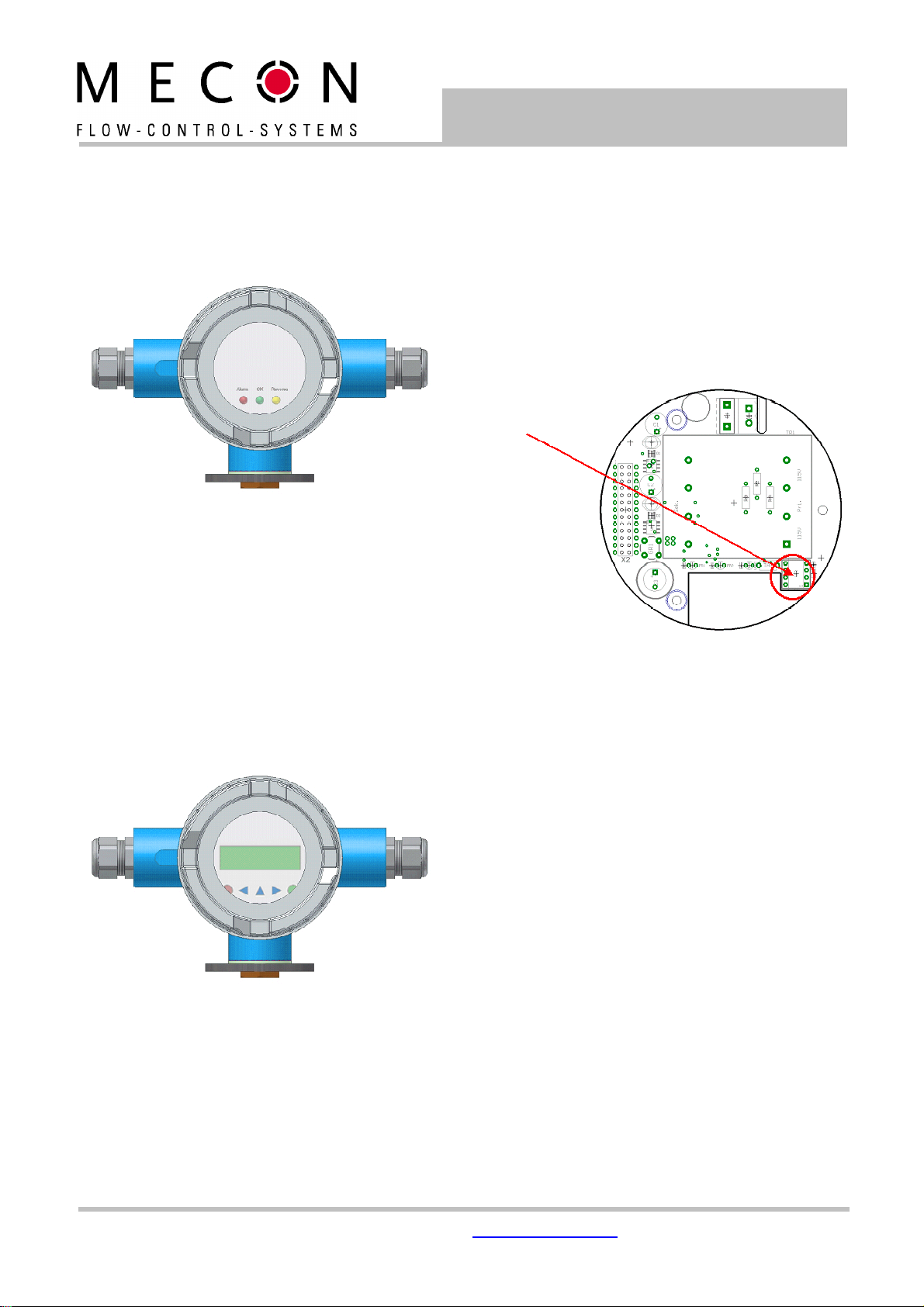
Data memory chip (DSM)
The replaceable data memory chip (DSM) is an EEPROM device in
D L-8 housing, located in a socket on the power supply board. t
includes all characteristic data of the sensor e.g. sensor constant,
version or serial number. Consequently, the memory module is
linked to the sensor and in case of a transmitter replacement it
has to remain by the sensor!
After replacing the transmitter or its electronics, the DSM will be
installed in the new transmitter. After the measuring system has
been started, the measuring point will continue working with the
characteristic values stored in the DSM. Thus, the DSM offers
maximum safety and high comfort when exchanging device
components.
Fig 5 Electronic, Power supply board mag-flux M1
At any exchange observe the polarity of the memory chip. Pin 1
is signed by a dot or a notch.
Safety of operation
A comprehensive self-monitoring system ensures maximum
safety of operation.
• Potential errors can be reported immediately via the
configurable status output. The corresponding error messages
will also be displayed on the transmitter display. A failure of
the auxiliary power can also be detected via the status output.
• When the auxiliary power fails, all data of the measuring
system will remain in the DSM (without back-up battery).
• All outputs are electrically isolated from the auxiliary power,
the sensor circuit and from each other.
Slot DSM

Mecon GmbH
Phone +49(0)241 41369 – 0 Fax +49(0)241 41369 – 40
Page 6 / 35
Ziegler traße 10 – 16
Mecon 02/2010 D-52078 Aachen
Tran mitter mag
-
flux M1
__ Input
Mea ured variable
Mass flow rate, temperature, density and volume flow (calculated
from the preceding measured variables).
Mea uring range
The measuring range, which varies according to which sensor is
used, can be found on the relevant data sheet or rating plate.
Operating the mag-flux flow probe with the mag-flux M1
The flow probes mag-flux M S 1/D und mag-flux M S 2/15 are
calibrated for flow velocity. n order to display the measured
value in volume flow units, it must be converted using the flow
velocity and the inside diameter of the tube. The following
parameters must be set at the mag-flux M1:
1. At the functional level
S
ENSORSETTINGS
+ M1
set the sensor
type mag-flux MIS. The dimension of the sensor constants will
be automatically adapted.
2. Setting of the sensor constant.
3. Set the nside diameter of the tube in xxx mm.
Important
The actual diameter has to be set, not the nominal
diameter of the tube!
4. At the functional class
F
LOW, set the desired unit of volume
flow.
5. Using the function
V
OLUME
F
LOW
U
PPER
-R
ANGE
V
ALUE set the
upper-range value
__ Output
Output ignal
All ignal output
Electrically isolated from each other and from ground (PE).
Analog output
• 0/4-mA current output, electrically isolated, optional with
HART®
• Volume flow or flow speed
(Using the HART®-protocol the current output has to be
assigned to volume flow in the mode of 4-20mA)
Pul e-/Frequency output
• Pulse duration adjustable range is 0,1 ... 2000 ms
(default value 50 ms)
(Mark-to-space ratio is 1:1, if the set pulse duration is not
reached.)
Important
When programming the pulse duration, a plau-
sibility check is carried out. f the selected pulse
duration is too long for the set upper range value,
an error message will be displayed.
• frequency output max. 1 kHz
• passive via optocoupler
UN = 24V
Umax = 30 V
max = 60 mA
Pmax = 1,8 W
Pul e value
The pulse value can be multiplied by a factor between 0.001-
100.0 (decade increments) of the selected pulse unit (e.g. m³)
Default: 1 pulse/unit
Statu output
• for: - forward and reverse flow,
- M N flow rate
- MAX flow rate
- alarm
• passive via optocoupler
UN = 24 V
Umax = 30 V
max = 60 mA
Pmax = 1,8 W
Failure ignal
A failure in the meter can be indicated via the current output or
the status output. The current output ca be set to a failure signal
(alarm) of < 3.8 mA or > 22 mA.
The status output can be configured as N/O or N/C contact.
Load for the current output
Standard version: ≤ 600 Ohm
HART® (minimum load) > 250 Ohm
Damping
Programmable from 0 to 60 seconds
Low flow cut-off
The low-flow cut-off can be set to values between 0 and 20%.
The set value refers to the upper range value. f the measured
value is lower than the set volume, the flow rate will set to 0.0
(l/h). This results in the analog output being set to 0/4 mA, and
the pulse output will stop generating pulses.
The configurable hysteresis takes effect only one side while
exceeding this limit.

Mecon GmbH Phone +49(0)241 41369 – 0
Fax +49(0)241 41369 – 40
Ziegler traße 10 – 16 www.mecon.de
cu tomer [email protected]
Page 7 / 35
D-52078 Aachen
Mecon 02/2010
Tran mitter mag-flux M1
__ Technical data
Reference condition
n conformity with EC 770:
temperature: T = 20°C
relative humidity: rH = 65%,
air pressure: p = 101,3 kPa
Mea uring tolerance
See characteristic values of the corresponding sensor.
Repeatability
See characteristic values of the corresponding sensor.
Influence of ambient temperature
• For the pulse output: ± 0,05 % per 10 K.
• For the current output: ± 0,1 % per 10 K.
__ Operating condition
In tallation condition
Caution
Additional cable glands (not contained):
The operator is responsible for that fact that
according to the enclosure and ignition enclo-
sure certified cable glands or screws are used.
The kind of threads is stamped on the rating
plate.
At the connection between sensor and trans-
mitter a metalized cable gland must be used for
the screen.
(See chapter „Connection of the magnetic cur-
rent and electrode line on page 9)
Compact ver ion
For the compact version the transmitter housing is mounted on
the sensor. Therefore no cable is necessary between sensor and
transmitter.
Remote ver ion
The transmitter needs to be mounted separately from the sensor
if:
• the mounting area is difficult to access,
• there is a lack of space,
• medium and ambient temperatures are extremely high,
• there is strong vibration.
Fig 6 Proper installation of cables at high humidity and wet conditions
The mag-flux M1 transmitter has to be mounted free of vibra-
tions!
Caution:
For the separate version, the minimum per-
missible conductivity of the medium is deter-
mined by the distance between the sensor and
the transmitter. The maximum cable length to
ensure accuracy is 200 m. For the cable type
see chapter „cable specification” on page 9.
Fig 7 Cable length for remote version
Important
• The electrode cable must be fixed. f the
conductivity of the medium is low, cable move-
ments may change the capacity considerably
and thus disturb the measuring signal.
• Do not lay the cables close to electrical
machines and switching elements.
• Equipotential bonding must be ensured be-
tween sensor and transmitter.
Caution
Do not connect or disconnect the field coil cable
before the primary power of the meter has been
disconnected!
Environmental condition
Ambient temperature range
- 20 °C to + 60 °C (-4°F to 140°F).
Below 0 °C the readability of the LCD display will be limited.
n the case of an outdoor installation, the device must be
protected against direct solar irradiation with a weather shield
Storage temperature
- 25 °C to + 60 °C (-13 °F to 140 °F)
Degree of protection
P67.

Mecon GmbH
Phone +49(0)241 41369 – 0 Fax +49(0)241 41369 – 40
Page 8 / 35
Ziegler traße 10 – 16
Mecon 02/2010 D-52078 Aachen
Tran mitter mag
-
flux M1
Caution
ngress protection P 67 is only achieved if
suitable and tightly screwed down cable glands
or conduits are used. f the cable glands are
only tightened manually water may leak into the
terminal compartment in the housing.
Danger
Particular care must be taken if the front window
of the housing becomes fogged over or dis-
colored because moisture, water or product
might seep through the wire sheath into the
terminal compartment in the housing!
Caution
Electromagnetic compatibility is only achieved if
the electronics housing is closed. Leaving the
enclosure open can lead to electromagnetic
disturbances.
Proce condition
Fluid temperature
The data sheet/rating plate of the connected transmitter is
binding. With directly mounted transmitter on the sensor
(compact version) the heat entry from the process to the
transmitter must be considered.
Pha e of Medium
Liquid.
Vi co ity
No restrictions.
The data sheet/rating plate of the connected sensor is binding.
Fluid temperature limit
The data sheet/rating plate of the connected sensor is binding.
Flow rate limit
The data sheet/rating plate of the connected sensor is binding.
Pre ure drop
The data sheet/rating plate of the connected sensor is binding.
Empty pipe detection
Transmitters, which are equipped with a LCD display, have an
selectable empty pipe detection. The operating reliability depends
on the conductivity of the liquid medium and the cleanliness of
the electrodes.
__ Con truction detail
Type of construction / dimensions
Fig 8 Transmitter housing – compact version
Fig 9 Transmitter housing – pipe mounting
Fig 10 Transmitter housing - wall mounting

Mecon GmbH Phone +49(0)241 41369 – 0
Fax +49(0)241 41369 – 40
Ziegler traße 10 – 16 www.mecon.de
cu tomer [email protected]
Page 9 / 35
D-52078 Aachen
Mecon 02/2010
Tran mitter mag-flux M1
Technical data mag-flux M1
Weight: 2,4 kg
Material: aluminum die-cast housing,
powder-coated
Process connection: Directly mounted on the sensor
(compact version) or connected via
cable (remote version).
Electrical connection: Mains
230 V AC, -15%/+10%, 50/60 Hz
115 V AC; -15%/+10%, 50/60 Hz
or
24 V DC; ±15 %
Power consumption: 10 VA
Mains fuse: 5 x 20mm (acc. D N 41571-3)
Rated voltage: 250V AC
Braking capacity: 80A@250V AC
Mains Rated current
250 V AC 100 mA (T)
115 V AC 100 mA (T)
24 V DC 1 A (T)
Electrical terminal
Fig 11 Electrical connections of the transmitter mag-flux M1
Fig 12 Electrical connection of the mag-flux M1
(remote version only)
Cable pecification
f the transmitter is mounted separately from the sensor, the
following cables must be used:
Electrode cable and field coil cable
as shielded twisted pair. n order to protect the cable from ex-
ternal interference, the twisted-pair wires are covered by an
additional, overall shield.
Cable
length
wire
cro ection
Example
≤ 10 m ≥ 0,25 mm² L YCY-CY TP 2x2x0,25 mm².
> 10 m ≥ 0,75 mm² SL YCY-C11Y (2x(2x0,75 mm²)).
The outer shield is groundet by means of special EMC-compliant
cable glands at both ends of the cable.
Wiring diagram
Connection of the ignal cable
• Lay the signal cables separately from cables with voltages >
60 V.
• Only use signal cables as specified in chapter „Electrode cable
and field coil cable“.
• Avoid laying signal cables close to large electrical installations
or use – if possible – only shielded cables.
• A load at least 250 Ω must exist in the signal circuit for error
free communication via the HART® protocol.
Fig 13 Mains and signal terminals of the transmitter
mag-flux M1
Terminal
Label Function
1 PE Protective conductor
2 N Mains
3 L Mains
4 Pulse - Pulse output (passive)
5 Pulse + Pulse output (passive)
6 Status - Status output (passive)
7 Status + Status output (passive)
8 Current - Current output (aktive)
9 Current + Current output (aktive)
Signal line
Power upply
Mecon GmbH
Phone +49(0)241 41369 – 0 Fax +49(0)241 41369 – 40
Page 10 / 35
Ziegler traße 10 – 16
Mecon 02/2010 D-52078 Aachen
Tran mitter mag
-
flux M1
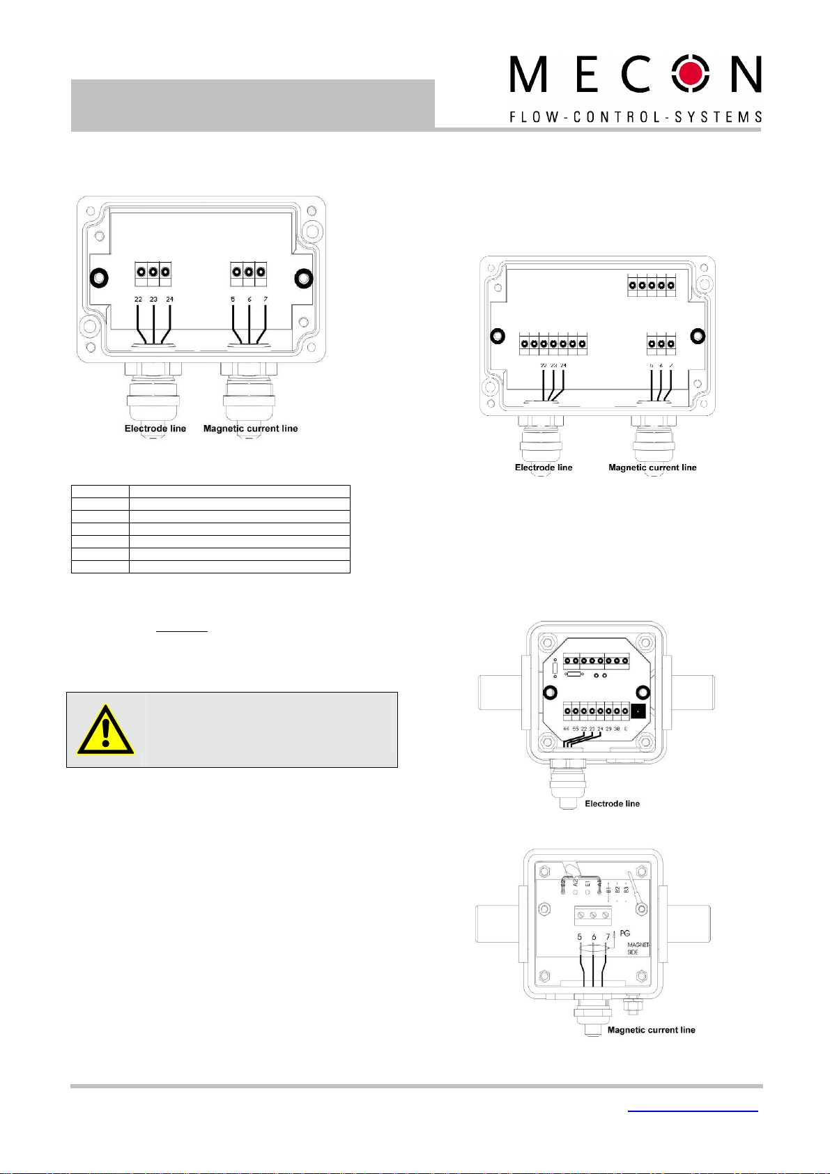
Connection of the magnetic current and electrode line
(remote ver ion only)
Fig 14 Connection diagram for sensor cable of the mag-flux M1
Terminal
Function
5 Magnetic field current 1
6 Magnetic field current 2
7 Potential equilization / PE
22 Measuring ground
23 Electrode 1
24 Electrode 2
For cable specifications see chapter „Electrode cable and field coil
cable“ on page 9.
The outer shield is grounded by means of special EMC-compliant
cable glands at both ends of the cable, the inner shields are
connected to terminal 7 and 22 respectively.
For terminal assignments see „Electrical terminals“ on page 9.
Caution
Do not connect or disconnect the field coil cable
before the primary power of the meter has been
disconnected!
Please observe also the advices in chapter „
Cable
pecification
” on page 9
Connection of the en or mag-flux A
The remote version of the sensor mag-flux A has a terminal box
as shown in Figure 15.
Feed the electrode line through the left gland and the magnetic
current line through the right gland and connect the cables as
shown in Figure 15.
Fig 15 Electrical connections of the mag-flux A sensor
Connection of the en or mag-flux F5
Feed the electrode line through the lower gland as shown in
Figure 16 and the magnetic current line through the upper gland
(see Figure 17) and connect the cables.
Fig 16 Electrical connections of the mag-flux F5 sensor (bottom)
Fig 17 Electrical connections of the mag-flux F5 sensor (top)

Mecon GmbH Phone +49(0)241 41369 – 0
Fax +49(0)241 41369 – 40
Ziegler traße 10 – 16 www.mecon.de
cu tomer [email protected]
Page 11 / 35
D-52078 Aachen
Mecon 02/2010
Tran mitter mag-flux M1
Connection of the en or mag-flux S and the flow probe
mag-flux MIS
These sensors are equipped with a pre-assembled cable ex-
factory. This cable is permanently connected to the sensor at one
end. The end leading to the transmitter is fitted with a cable
gland and pre-prepared cable ends for connection. The attached
wire numbers serve for orientation.
Fig 18 Connections of the sensor mag-flux S and the probes
An chlu HART®
A number of options are available for HART® communication.
However, for all these options loop resistance must be less than
the maximum load specified in Chapter „Outputs“ (see page 6).
The HART®- nterface is connected via terminals 8 and 9 of the
(active) current output.
The minimum load impedance is 250Ω.
.
Fig 19 Electrical connection for HART
®
communication, schematic diagram
Di play and operator interface (ba ic ver ion)
Zero point adju tment
Below the mains transformer, next to the lights and the data
storage module (DSB), there is a switch for adjusting the zero
point. n order to reach the switch, the transducer must be
opened by unscrewing the front cover and removing the
decoration foil.
For processing the zero point adjustment please observe the
advices in Section “Zero point calibrationon” on page 4.
Fig 20 Switch for zero point adjustment
LED di play
The actual operating status information of the mag-flux M1 is
displayed by three LED for the basic version:
Fig 21 Status-LED of the mag-flux M1 (basic version)
off Not powered green LED
flashing Power on
off Flow direction forward yellow LED
on Flow direction reverse
off Normal operation
flashing Limit exceeded
red LED
on Malfunktion

Mecon GmbH
Phone +49(0)241 41369 – 0 Fax +49(0)241 41369 – 40
Page 12 / 35
Ziegler traße 10 – 16
Mecon 02/2010 D-52078 Aachen
Tran mitter mag
-
flux M1
Maintenance and repair
The transmitter mag-flux M1 is designed for maintenance-free
performance. t contains no parts, which have to be replaced or
adjusted cyclically.
While commissioning or maintenance, mains power must be
switched off. Do not connect or disconnect the wiring between
sensor and transmitter while power is on!
Main fu e
The mains fuse is located in the terminal compartment. Before
replacing the fuse, the power has to be switched off. Check
carefully that the transmitter is voltage free. The fuse may only
be replaced by the exactly same type of fuse! (See also chapter
„Technical data mag-flux M1“on page 9).
Replacement of terminal board
The terminal board is located in the terminal compartment.
Before replacing the board, the power has to be switched off.
Check carefully that the transmitter is voltage free. The board
may only be replaced by the exactly same type of board.
To replace the terminal board, all pluggable connectors have to
be released first and the 4 fixing screws have to be loosened.
For the assembly of the new board ensure, that the screws are
secured again by toothed washers. Only after all connectors are
plugged in, the power can be switched on again
Replacement of tran mitter electronic
The transmitter electronic may be replaced only as complete
module. With the exchange of individual components the trans-
mitter is afterwards no longer calibrated neither regarding its
measuring characteristics nor its analog outputs. The exchange
has to be done as described in the following:
1. Switch off the power supply.
2. Open the terminal compartment and unplug the 6-pole con-
nector.
3. Open the front cover and remove the decoration foil by
loosing the three mounting screws and if necessary the
display board inside the electronic compartment by loosing
the three thread bolts.
4. Unplug the green connector on the power supply board
5. Screw out the 3 thread bolts and after that extract the
power supply board carefully.
6. Disconnect the sensor’s wires on the main board. Please
memorize the correct order of the wires.
7. Screw out the 3 thread bolts and extract the main board
carefully – please take special care of the flatcable leading
to the terminal compartment.
9. The data memory chip (DSM) has to be changed over to the
new electronic stack (see also chapter „data memory chip
(DSM)” on page 5).
10. nsert the new main board and feed the flatcable through
the hole in the compartment partitions wall.
11. Assemble the transmitter reverse to items 1 to 7 of this list.
12. Before powering on, check all connectors to be plugged in
correctly and all wires and devices are fixed.
After the exchange the transmitter is calibrated by the take-over
of the data memory chip (DSM) for the sensor. All totalized
counts and settings are taken on.
__ mag-flux M1 control unit (Option)
Introduction
The transmitter mag-flux M1 can be operated depending on con-
figuration by using a control unit or via a HART® interface.
Below the operation and parameterization of the transmitter is
described using the control unit. t is located in the electronic
compartment and covered by an inspection window.
Fig 22 Transmitter mag-flux M1 with control unit (optional)
Di play
The control unit in the mag-flux M1 has an integrated back
lighted, alphanumeric display with two 16-character lines (format
16 x 60 mm). Measurement data and settings can be read direct-
ly from this display.
The LCD display is designed to be operated at temperatures
ranging from − 20 °C to + 60 °C (-4° F to 140 °F) without being
damaged. However, near-freezing temperatures the display be-
comes slow and the readability of the measured values is re-
duced. At temperatures below − 10 C° (14 °F), only static values
(parameter settings) can be displayed. At temperatures
exceeding 60 C° (140 °F), contrast decreases substantially on
the LCD and the liquid crystals can dry out.
Other manuals for mag-flux M1
1
Table of contents
Popular Transmitter manuals by other brands


Intellinet
Intellinet 561211 Quick instruction guide

Extron electronics
Extron electronics MTP 15HD A Series Setup guide

Hall Technologies
Hall Technologies DSCV1-70-TX user manual

ATX
ATX QFOT1L Installation & operation manual

Topseed
Topseed TSFC-2401 user manual

Badger Meter
Badger Meter 340 MB Btu Series Installation & operation manual


