Chamberlain Liftmaster 333LM User manual

Use a screwdriver to pry open the receiver cover (see
illustration).
The slide switch is factory set to the N.C. position
(otherwise the opener will not operate). Verify this
setting .
• Select a remote control push button to STOP the
opener. (RED is recommended.)
• Press and hold the selected remote push button.
•Then press and release the “learn” button labeled
“A” on the receiver. The adjacent indicator light will
FLASH. Release the remote push button.
Repeat the procedure above with the yellow remote
push button and receiver “learn” button “B” to program
the CLOSE operation; and again with the green
remote push button and receiver “learn” button “C” to
program the OPEN function of the opener.
Return the front cover to the receiver.
(For this application, code switch settings need not be
changed.)
Model 333LM
3-Button
Remote Control Transmitter
The 333LM 3-Button Remote Control Transmitter
can be used with a 323LM 3-channel receiver and
a 3-button door control to operate a commercial
door opener in open, close, and stop mode (as
explained on side 1).
It can also be used with other 315MHz
transmitters to operate a garage door opener, in
which case the code switches in all transmitters
must be set to match (see side 2).
Side 1
NOTICE: To comply with FCC and or Industry Canada (IC) rules, adjustment or
modifications of this receiver and/or transmitter are prohibited, except for changing the
code setting or replacing the battery. THERE ARE NO OTHER USER SERVICEABLE PARTS.
Tested to Comply with FCC Standards FOR HOME OR OFFICE USE. Operation is subject to
the following two conditions: (1) this device may not cause harmful interference, and
(2) this device must accept any interference received, including interference that may cause
undesired operation.
ABC
OPENING RECEIVER
Remote control
push buttons
Connect
Antenna
Open
Close
Stop
Slide Switch – N.C. Position
To use the transmitter with a 3-channel receiver and 3-button door control
to operate a commercial door opener:
323LM 3-Channel Receiver
OWNER’S MANUAL
Install the control station and receiver where the door is
visible, but away from the door and its hardware. When a
receiver is used to activate a commercial door opener, a
reversing edge MUST be installed on the bottom of the door.
Failure to install a reversing edge under these circumstances
may result in SERIOUS INJURY or DEATH to persons trapped
beneath the door.
WARNING
CAUTION WARNING
WARNING
NOTE: If a remote control push button is not
pressed within 30 seconds, the indicator light
adjacent to the selected “learn” button will turn OFF.
In that case, repeat the programming.

© 2005, The Chamberlain Group, Inc.
114A3102 All Rights Reserved Printed in Mexico
The green button is recommended for use with a
garage door opener. The other push buttons can be
used to operate another opener and/or light control
product.
Slide back the battery compartment cover to access
the code switches in the NEW remote control.
NOTE 1: In 3-button remote controls, only code
switches 2 through 9 must be set to matching
positions. Code switch #1 is neutral. Set it to any
position. It will not affect the code.
NOTE 2: If 3- and single-button remote controls will
be used to operate the same receiver, set code
switch #1 in the single-function remote control to
match the multi-function push button selected. (See
illustration below for code positions matching
multi-function remote control push buttons.)
MATCH/CHANGE THE CODE IN NEW AND EXISTING REMOTE CONTROL TRANSMITTER(S)
SET CODE SWITCHES IN ALL REMOTE CONTROL TRANSMITTERS TO MATCHING POSITIONS
For use with other remote control transmitters to operate a
garage door opener:
Side 2
To prevent possible SERIOUS INJURY or DEATH from
electrocution:
• Be sure power is not connected BEFORE installing the
receiver.
To prevent possible SERIOUS INJURY or DEATH from a
moving gate or garage door:
• ALWAYS keep remote controls out of reach of children.
NEVER permit children to operate, or play with remote control
transmitters.
• Activate gate or door ONLY when it can be seen clearly, is
properly adjusted, and there are no obstructions to door
travel.
• ALWAYS keep gate or garage door in sight until completely
closed. NEVER permit anyone to cross path of moving gate or
door.
WARNING
CAUTION
WARNING
WARNING
ATTENTION
AVERTISSEMENT AVERTISSEMENT
AVERTISSEMENT
123456789
+
0
123456789
+
0
123456789
+
0
Model 361LM
Single-Button Remote Control
(12 Volt Battery)
Single-Button Remote Control
(9 Volt Battery)
Model 362LM
2-Button Remote Control
(12 Volt Battery)
Code Switches (1-9) Button 1
Code Switches (1-9)
Button 2
Code Switches (1-9)
Tab
Match
Code
Switches
(1-9)
Match
Code
Switches
(1-9)
123456789
+
0
Model 363/333LM
3-Button Remote Control
(12 Volt Battery)
Code Switches (1-9)
Match
Code
Switches
(2-9)
Code switch #1 in a
3-Button
Remote Control
is neutral - set it
to any position.
When used with
Multi-Function Remote,
set code switch #1 to
match push button
selected.
12345678
+
0
9
Code Switches (1-9)
3-Button Remote Control
(9 Volt Battery)
1
2
3
4
5
6
7
8
+
0
9
Code Switches (2-9)
2. Place remote controls side by side as shown. Set
the code switches in the new remote control to the
same positions as in the original remote control.
Use a screwdriver or pen to slide the switches.
Refer to note above regarding code switch #1
in 3-Button Remote Controls.
If you want to keep the same code, proceed as
follows (refer to the illustration of your model remote
control):
1. Locate code switches in original remote control(s),
either by sliding the battery compartment cover
back or by removing the cover screw and turning
case over (push button side up). When you set the
case bottom aside, be careful to avoid moving
circuit board components.
Visor clip . . . . . . . . . . . . . . . . . . . . . . . . . . . . . . . .29C128
9Vbattery . . . . . . . . . . . . . . . . . . . . . . . . . . . . . . . . .10A2
12Vbattery . . . . . . . . . . . . . . . . . . . . . . . . . . . . . . .10A14
Owner’s manual - Spanish . . . . . . . . . . . . . .114A3102SP
REPLACEMENT PARTS

• Use un destornillador para separar abierta la
cubierta del receptor (vea la ilustración)
El conmutador corredizo se gradúa de fábrica a
la posición N.C. (de otra manera el abre-puertas
no funciona). Verifique esta graduación.
• Seleccione un botón de control remoto para
PARAR el abre-puertas. (se recomienda ROJO).
• Oprima y mantenga oprimido el botón de remoto
seleccionado.
• A continuación oprima y suelte el botón de
“aprendizaje” rotulado “A” en el receptor. La luz
indicadora adyacente CENTELLEA. Suelte el
botón remoto.
Repita el procedimiento de arriba con un amarillo
botón remoto y un botón “B” de “aprendizaje” del
receptor para programar la operación de CLOSE y
nuevamente con el último botón remoto y el botón
“C” de “aprendizaje” del receptor para programar la
función OPEN del abre-puertas.
Retorne la cubierta delantera al receptor.
(Para esta aplicación, no es necesario cambiar los
ajustes de códigos.)
Modelo 333LM
Control Remoto Transmisor
de 3 Botones
El transmisor de control remoto de 3 botones
333LM puede usarse con un receptor de 3
canales 323LM y un control de puerta de 3
botones para operar un abre-puertas comercial
en la modalidad de abrir, cerrar y parada (según
se explicó en el lado 1).
También se puede usar con otros transmisores
de 315 MHz para hacer funcionar un abre-puertas
del garaje, en cuyo caso los interruptores de
códigos de todos los transmisores deben fijarse
para que coincidan (vea el lado 2).
Lado 1
ABC
Botones del
control remoto
Conmutador corredizo – Posición N.C.
Conecte
la antena
Abra
Cierre
Corte
ABRIR EL RECEPTOR
NOTA: Si no se oprime un botón de control remoto dentro
de 30 segundos, la luz indicadora adyacente al botón de
“aprendizaje” se apaga. En ese caso repita la programación.
Para usar el transmisor con un receptor de 3 canales y un control de puerta de 3
botones a fin de operar un abre-puertas comercial:
323LM 3-Channel Receiver
MANUAL DEL PROPIETARIO
AVISO: Para cumplir con las reglas de la FCC y/o de Canadá (IC), las reglas, ajustes o
modificaciones de este receptor y/o transmisor están prohibidos, excepto por el
cambio de la graduación del código o el reemplazo de la pila. NO HAY OTRAS PIEZAS
REPARABLES DEL USUARIO.
Se ha probado para cumplir con las normas de la FCC para USO DEL HOGAR O DE LA
OFICINA. La operación está sujeta a las dos condiciones siguientes:(1) este dispositivo
no puede causar interferencia perjudicial, y (2) este dispositivo debe aceptar cualquier
interferencia recibida, incluyendo la interferencia que puede causar una operación no
deseable.
Instale la estación de control y el receptor donde la puerta sea
visible, pero alejado de la puerta y la tornillería. Cuando se
usa unreceptor para activar un abre-puertas comercial, DEBE
instalarse un borde revertido en la parte inferior de la puerta.
El no instalar unborde revertido bajo esas circunstancias
puede resultar en LESIONES GRAVES o la MUERTE a las
personas atrapadas debajo de la puerta.
ADVERTENCIA
ADVERTENCIA
ADVERTENCIA
ADVERTENCIA

© 2005 The Chamberlain Group, Inc.
114A3102SP Todos los derechos reservados Impreso en México
123456789
+
0
123456789
+
0
123456789
+
0
Modelo 361LM
Control remoto de una sola botón
(pila de 12 voltios)
Control remoto de una sola botón
(pila de 9 voltios)
Modelo 362LM
Control remoto de 2 botones
(pila de 12 voltios)
Interruptores de códigos (1-9) Botón 1
Interruptores de códigos (1-9)
Botón 2
Interruptores
de códigos (1-9)
Lengüeta
Haga coincidir
los interruptores
de códigos (1-9)
Haga coincidir
los interruptores
de códigos (1-9)
123456789
+
0
Modelo 363LM/333LM
Control remoto de 3 botones
(pila de 12 voltios)
Interruptores de códigos (1-9)
Haga coincidir
los interruptores
de códigos (2-9)
El interruptor de códigos
N1 de un control remoto
de 3 botones es neutral
—fíjelo en cualquier posición.
Cuando se usa con un control
remoto de 3 botones, fije el
interruptor de código N1
de modo que coincida con el
botón seleccionado.
12345678
+
0
9
Interruptores de códigos (1-9)
Control remoto de 3 botones
(pila de 9 voltios)
1
2
3
4
5
6
7
8
+
0
9
Interruptores de códigos (2-9)
Se recomienda usar el botón verde con un abre-puertas
del garaje. Los otros botones se pueden usar para hacer
funcionar otro abre-puertas y producto de control
luminoso.
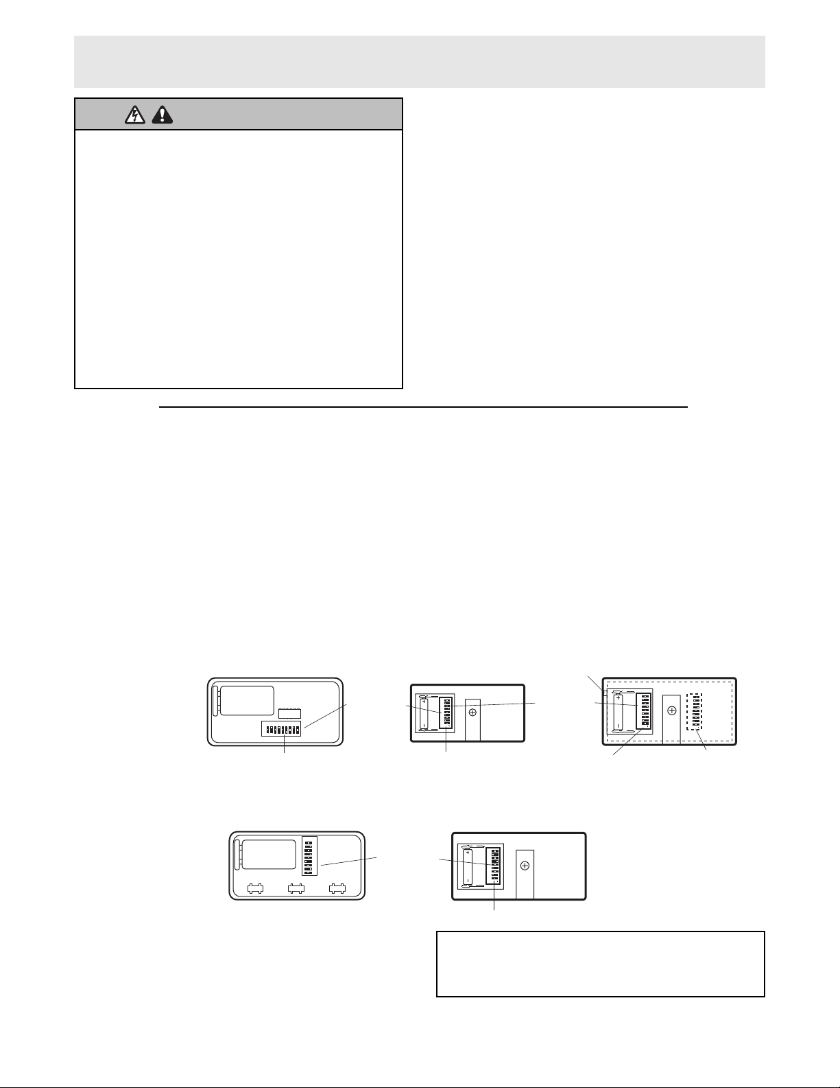
Vuelva a deslizar la tapa del compartimiento de la pila
para tener acceso a los interruptores de códigos en el
NUEVO control remoto.
NOTA 1: En los controles remotos de 3 botones, sólo se
deben fijar los interruptores de código 2 a 9 en posiciones
que coincidan. El interruptor de código N°1 es neutral.
Fíjelo en cualquier posición. No afectará al código.
NOTA 2: Si se van a usar controles remotos de una sola
botón o de 3 botones para hacer funcionar el mismo
receptor, fije el interruptor de código N°1 en el control
remoto de una sola botón para que coincida con el botón
de 3 botones seleccionado. (Vea en la ilustración de
abajo las posiciones de los códigos que coinciden con los
botones de control remoto de 3 botones).
HAGA COINCIDIR/CAMBIE EL CÓDIGO EN LOS TRANSMISORES DE CONTROL REMOTO NUEVOS Y EXISTENTES
FIJE LOS INTERRUPTORES DE CÓDIGOS DE TODOS LOS TRANSMISORES DE CONTROL REMOTO EN
POSICIONES QUE COINCIDAN
Lado 2
Para usar con otros transmisores de control remoto a fin de hacer
funcionar un abre-puertas del garaje:
2. Ponga los controles remotos uno al lado del otro según
se muestra. Fije los interruptores de códigos en el nuevo
control remoto en las mismas posiciones que en el
control remoto original. Use un desarmador o pluma para
deslizar los interruptores. Consulte la nota de arriba
referente al interruptor de códigos N°1 en los
controles remotos de 3 botones.
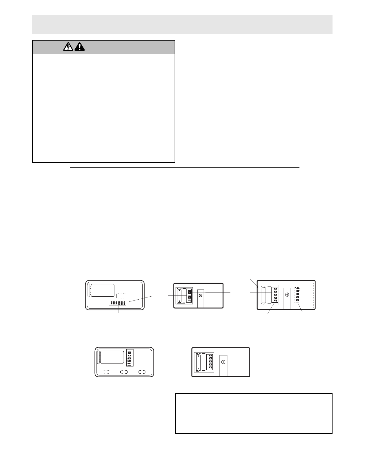
Si desea mantener el mismo código, haga lo siguiente
(consulte la ilustración de su modelo de control remoto):
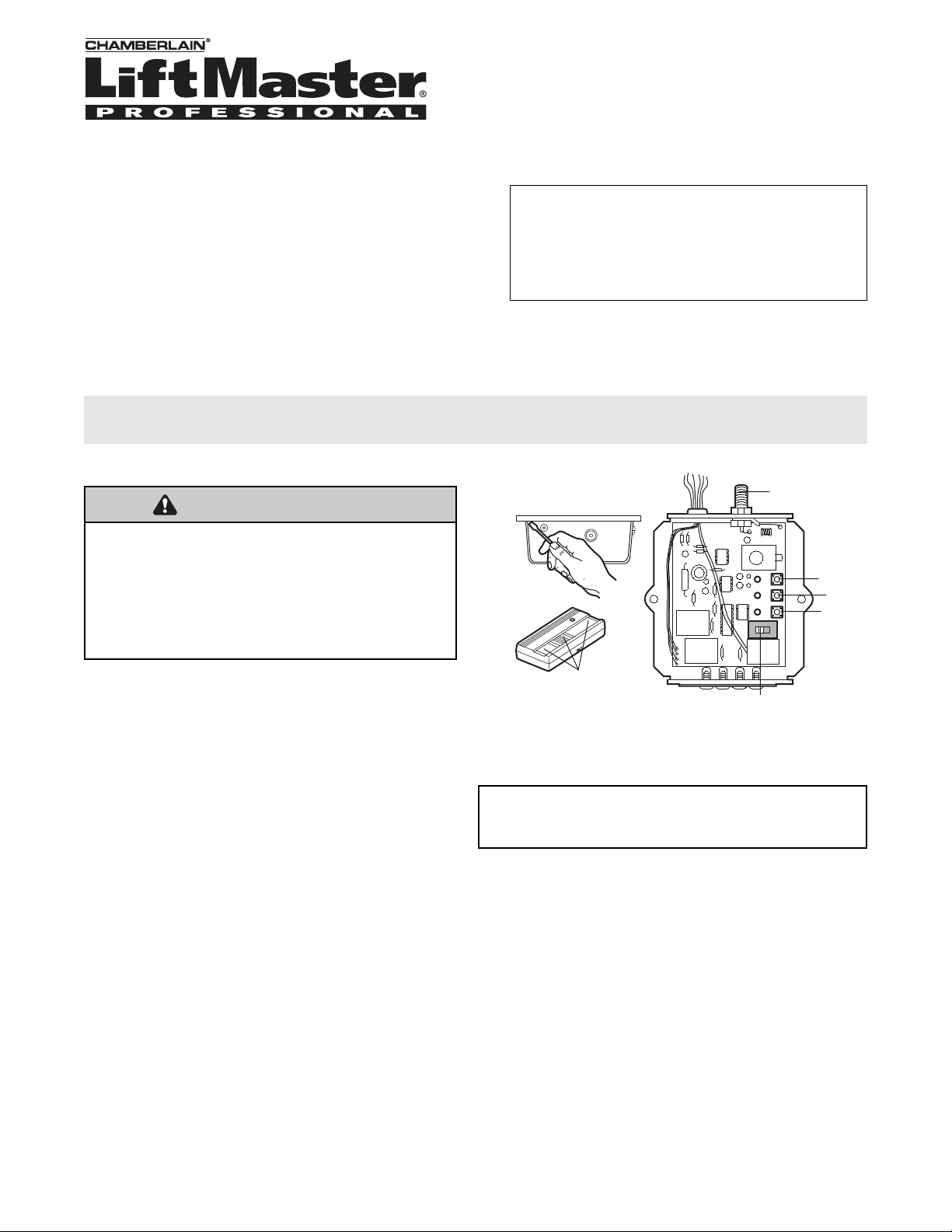
1. Localice los interruptores de códigos en los controles
remotos originales, ya sea deslizando hacia atrás la tapa
del compartimiento de las pilas o quitando el tornillo de
la tapa y volteando la caja (lado de los botones hacia
arriba).Cuando ponga a un lado la parte inferior de la
caja, tenga cuidado de no mover los componentes
del tablero de circuitos.
Para prevenir LESIONES GRAVES o MUERTE posible por
electrocución:
• Asegurarse que la electricidad no está conectada ANTES de
instalar el receptor.
Para prevenir LESIONES GRAVES o MUERTE por una entrada o
puerta de garaje móvil:
• Mantener SIEMPRE los controles remotos fuera del alcance
de los niños. No permitia NUNCA que los niños operen, o
jueguen con transmisores de control remoto.
• ACTIVAR la entrada o puerta SÓLO cuando pueda verse
claramente, esté bien ajustada, y no haya obstrucciones al
recorrido de la puerta.
• Mantener SIEMPRE la entrada o puerta del garaje a la vista
hasta que esté completamente cerrada. NUNCA permitia que
alguien cruce la trayectoria de una entrada o puerta móvil.
ADVERTENCIA
ADVERTENCIA
ADVERTENCIA
ADVERTENCIA
Presilla de la visera . . . . . . . . . . . . . . . . . . . . . . . 29C128
Pila de 9V . . . . . . . . . . . . . . . . . . . . . . . . . . . . . . . . .10A2
Pila de 12V . . . . . . . . . . . . . . . . . . . . . . . . . . . . . . .10A14
PIEZAS DE REPUESTO
Table of contents
Languages:
Other Chamberlain Transmitter manuals

Chamberlain
Chamberlain RTXW1 User manual

Chamberlain
Chamberlain RTXW2 User manual

Chamberlain
Chamberlain 959CB User manual

Chamberlain
Chamberlain TC1 User manual

Chamberlain
Chamberlain LMWETXU User manual

Chamberlain
Chamberlain RTX8P-10 User manual

Chamberlain
Chamberlain LiftMaster 61LM User manual

Chamberlain
Chamberlain LMWEKITU User manual

Chamberlain
Chamberlain 4330E User manual

Chamberlain
Chamberlain RTX1P User manual