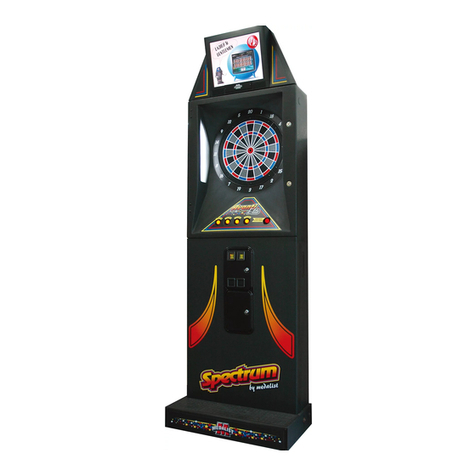
Medalist Spectrum Avanti Elite Operating and safety instructions

AIM FOR EXCELLENCE
Please read these instructions carefully before
setup and installation of the machine.
Keep this manual in a safe place for future
reference.
BASIC SETUP AND
INSTALLATION MANUAL

Safety Precautions
1. Basic Specifications
2. Spectrum Avanti Parts
3. Cabinet Configuration
4. Assembly And Installation Instructions
5. Camera Installation And Setup
6. Technical Information
6A. Exploded Drawing
6B. I.O. Board Layout
6C. Main Board Connections
6D. Wiring Diagram
7. Troubleshooting
8. Software Settings
9. Program Mode Diagram .............................................
1
2
3
4
7
11
12
12
20
22
23
24
26
30
.........................................................
...................................................
.......................................
................................................
......................
...................................
.................................................
................................................
.................................................
...................................
....................................................
.........................................................
......................................................
Table Of Contents

1. Before power is connected, confirm the game is level. If the game is
not level/stable, adjust the leg levelers.
2. The Spectrum Avanti is equipped with a grounded AC line plug.
This safety feature allows the plug to fit into any local grounded power
outlet. If ground is not present in AC system the Aux ground should be
properly connected to the nearest ground point. If you have any problems,
contact a licensed electrician.
3. Operate the dart board from a power source as indicated in the
specification of this manual. If you are not sure what type of power
you have, consult your local power company.
4. Overloaded AC plugs, power strips, extension cords, frayed power
cords and broken plugs may cause system overload and/or fire.
5. DO NOT allow anything to rest upon or roll over the power cord.
6. DO NOT place the dart board where the power cord is subject to
damage.
Safety Precautions
Caution
Spectrum Avanti has been engineered and manufactured to ensure
personal safety. However, improper use can result in potential electrical shock
or fire hazard. You must observe the following basic rules for installation, use
and servicing. Failure to do so may defeat the safe guards incorporated into
the Spectrum Avanti and may result in injury.
1. It is critical that the step/dart skirt is installed and the board is leveled
prior to opening the upper cabinet door to prevent the game from
falling over.
2. Be extremely careful when moving the dart board into position; leg
levelers may catch on the floor causing the dart board to tip over.
3. Always unplug the power to the dart board before moving.
4. To reduce the risk of fire or electrical shock, DO NOT expose the dart
board to any moisture.
5. To reduce the risk of electrical shock or possible death, DO NOT
touch these areas where high voltage is present; power supply,
voltage terminal strip and lamps.
Warning
1

2
1-Basic Specifications
5. I.O. Board
Designed and developed by Medalist
I.O. board software version 5.4
3. Monitor
Screen 17” LCD 15” LCD
Height
Depth
Width
4
8”
29”
½”
2. Step Extension
*Main board and power supply specifications are subject to change without notice
Height
Width
Depth
Weight
Max environment temperature
94½” 86½”
with LCD monitor installed with crown installed
Top Mount Mid Mount
without LCD monitor installed without crown installed
79¾” 75 ” ½
29” 29”
13¾” 13¾”
95 kilos, 209 pounds 94.5 kilos, 208 pounds
105 F
1. Main Unit
Make/model
CPU
Memory
Embedded peripherals
MSI K8MM-V
AMD, Socket 754, Sempron 2600/2800
256 MB/DDR
Audio, video, USB, LAN
4. *Motherboard
Type
Input
Output
Max output power
ATX
120/230 VAC (selectable)
+3.3Vdc/28A
+5Vdc/40A
+12Vdc/12A
-5Vdc/0.3A
-12Vdc/0.8A
400W
6. *Power Supply

3
Unpacking And Inspection
Parts List
1. Remove Spectrum Avanti lower cabinet, upper cabinet,
step/dart skirt and LCD monitor/crown from the boxes and
inspect for any damage.
2. Confirm that all parts are included.
2-Spectrum Avanti Parts Check List
1.
2.
3.
4.
5.
6.
Spectrum Avanti upper cabinet assembly
Spectrum Avanti lower cabinet assembly
LCD monitor assembly
Step/dart skirt assembly
Hardware kit
A. Step skirt mounting bolts (4)
B. Monitor/crown assembly bolts (3)
C. Key set (2)
Accessory kit
A. Bar darts (6)
B. Bar dart tips (1 bag)
C. Throw line (1)

3-Cabinet Configuration
4
Figure 1.1: Cabinet configuration (T)
Front Side Back
1) LCD Monitor
2) Camera (Optional)
3) Target
4) Select/Change
Button-Red
5) Player Button-Yellow
6) Coin Door
Bill Validator (Optional)
7) Mail Slot
8) Fan-Air Out
9) Hand Cup
10) AC Input
11) Soft Shutdown Switch
13) GND Terminal
12) Back Door
14) Speaker
15) Fan-Air In
(Fan With Filter)

5
Figure 1.2: Cabinet configuration (M)
3) LCD Monitor
4)
Change Button-Red
Select/
5) Player Button-Yellow
1) Camera (Optional)
2) Target
6) Coin Door
Bill Validator (Optional)
7) Mail Slot
8) Fan-Air Out
9) Hand Cup
10) AC Input
11) Soft
Switch
Shutdown
12) Back Door
13) GND Terminal
14) Speaker
15)
Front Side Back
Fan-Air In
(Fan With Filter)

6
Function
Name
Item
LCD Monitor
For display. Can adjust the display
quality by using the LCD button under
the LCD button cover
Camera For Player and Top Ten List pictures
Target Primarily to register dart scores,
to input various information
also used
Select/
Change Button-Red
Interfaces with software. Normally this button
is used to scroll cursor and change players
Player Button-Yellow
Interfaces with software. Normally this
button is used for selecting games and
selecting the number of players to play
the game
Coin Door
11
14
12
15
13
10
1
8
2
3
4
5
6
7
9
Mail Slot To send mail to operators/dealers, such
as records of tournaments or league
Fan-Air Out To blow hot air from inside the cabinet out
Hand Cup For transportation and assembly of
the cabinet
Where coins are inserted/DBA knockout plate
Speaker Sound
Fan-Air In To bring filtered air from outside the
cabinet in
GND Terminal Connects the cabinet ground to earth ground
AC Input Insert for the AC power cord
Soft Shutdown Switch
Back Door
Use for software shutdown (recommended)
Additional access door
Technical Information

7
4-Assembly And Installation Instructions
1. Install the leg levelers to the bottom of the lower cabinet.
2. Place the lower cabinet in the desired location and adjust
each leg leveler until the lower cabinet is level from front to
back and side to side.
3. Install the step/dart skirt assembly flush to the floor using
the four bolts provided.
Figure 2.1: Installation of lower cabinet Figure 2.2: Lower cabinet complete unit
Leg Leveler
A bolt set consists of a
M8 bolt, a lock washer
and a washer

Figure 3.1: Installation of upper cabinet (T)
*For top mount board only
*
Figure 3.2: Upper cabinet complete unit (T)
8
Locks
*
4.
on top of the lower cabinet.
5. With someone stabilizing the upper cabinet, open the
back door and lock the four hook latches to secure the upper
cabinet to the lower cabinet.
6. Install the monitor/crown to upper cabinet using the three
bolts provided.
7. Route the VGA cable up through the hole in the top of
the cabinet and connect it to the LCD.
8. Route the LCD power connector down through the hole in the
top of the cabinet and connect it to the 9 pin power connector
inside the cabinet.
Using two people, lift the upper cabinet and place it
Install 1 bolt
from outside
LCD
Monitor Unit
Upper Cabinet
Install 2 bolts
from inside
Fiber Door
Camera
(Optional)

9
Figure 4.1: Install upper cabinet
to lower cabinet (T)
Figure 4.2: Complete unit
installation (T)
Figure 4.3: Open the back door to
lock the hook latches (T)
Lock hook latches
Connect the lower
harness set with the
upper harness set.
Then connect VGA,
DB9 and Audio cables
to the main board. Back Door
Access
9.
upper wiring harness.
10. Connect the power cord to power input module on the back
of the cabinet.
11. Adjust leg levelers as needed then proceed to game setup.
12. Double check all of the connections before powering up the
Spectrum Avanti .
13. Lock the fiber door with key.
Connect the connectors from the lower wiring harness to the

10
Figure 4.3: Install upper cabinet
to lower cabinet (M)
Figure 4.4: Complete unit
installation (M)
Figure 4.5: Open the back door to
lock the hook latches (M)
Lock Cabinet
Latches (4)
Back Door
Access
Connect the lower
harness set with the
upper harness set.
Then connect VGA,
DB9 and Audio cables
to the main board.

5-Camera Installation And Setup
(Digital Camera Optional)
1. Thread the USB camera cable through the 1” hole in the upper
right side of the game.
2. While holding the camera box to the upper right hand side of the
game with the camera hole facing outwards, thread two 6mm bolts
from the inside of the game into the camera box inserts.
3. Plug the USB camera cable into one of the two USB ports.
1. Press the Program Mode Access Button located on the I.O. board to
enter game setup mode. Go to Diagnostics/Webcam test to set focus.
Go to Game Settings/Player Pix to set pricing and the Photo Delete
password.
2. Adjust focus by turning the black focus ring around the camera lens.
Focus the camera to the distance of the throw line.
3. To access Photo Delete without entering the Operators' Setup Mode,
go to Main Menu/Player Pix. Press and hold the Yellow Player Buttons
two and three simultaneously. This will take you to the enter password
screen. The password is entered by using the Yellow Player Buttons.
Once the password is accepted, follow the screen prompts to
delete photos.
Note: The Photo Delete password is set in Game Settings/
Player Pix by using the Yellow Player Buttons to set a numeric
password that corresponds to the Yellow Player Buttons
(i.e. 1111 equals pressing the player one button four times).
The password must be four to eight numbers in length.
Installation
Setup
11

12
6-Technical Information
Fluorescent Lamp Assembly
(Electrical, PA 0618)
Ballast-110
(Electrical, PA 0620 1)
Fluorescent Lamp
(Electrical, PA 0619)
I.O. Board
(Electrical, PE 0609)
ATX Power Supply
Power Input Module
(Electrical, PA 0623)
Hand Cup
(Cabinet, PA 0121)
Fan
(Electrical, PE 0612)
Main Board
Mounting Strap-
Power Supply
Speaker
(Electrical, PA 0626)
Starter-110
(Electrical, PA 0621 1)
(Electrical, PE 0614)
Hard Drive
And Rack
6A. Exploded Drawing
Figure 5.1: Exploded upper cabinet (T)
Camera
(Optional)
(Electrical, PE 0601)
(Electrical, PE 0608 L)
(Cabinet, PE 0137)
Hand Cup
(Cabinet, PA 0121)
Cabinet Latch
(Cabinet, PA 0114)
(Cabinet, PE 0610 L)

(Cabinet, PE 0137)
Figure 5.2: Exploded upper cabinet (M)
Speaker
(Electrical, PA 0626)
Starter-110
(Electrical, PA 0621 1)
Ballast-110
(Electrical, PA 0620 1)
Fluorescent Lamp
(Electrical, PA 0619)
Fluorescent Lamp Assembly
(Electrical, PA 0618)
I.O. Board
(Electrical, PE 0609)
Mounting Strap-
Power Supply
ATX Power Supply
(Electrical, PE 0614)
Fan
(Electrical, PE 0612)
Power Input Module
(Electrical, PE 0623)
Hand Cup
(Electrical, PA 0121)
Cabinet Latch
15" LCD Monitor
(Video, PA 0508)
LCD Button Cover
(Cabinet, PA 0143)
LCD Rack
(Cabinet, PA 0129)
Hard Drive And Rack
Main Board
Camera (Optional)
13
(Electrical, PE 0608
Cabinet, PE 0610)
(Electrical, PE 0601)
(Cabinet, PE 0114)

Figure 6.1: Exploded door (T)
14
Door
(Door, PA 0021)
Light Diffuser
(Cabinet, PE 0124 R)
Catch Ring Section
(Dart Head, PG 0221)
Diffuser Mounting Nut
(Cabinet, PA 0125)
Light Diffuser
(Cabinet, PE 0124 L)
Wing Nut, Star Washer
(Dart Head, PA 0219)
Catch Ring Screw
(Dart Head, PA 0222)
Player Button-Yellow
(Electrical, PA 0627)
Select/Change Button-Red
(Electrical, PA 0628)

15
Figure 6.2: Exploded door (M)
Light Diffuser
(Cabinet, PO 0124 R)
Light Diffuser
(Cabinet, PO 0124 L)
Door
(Door, PE 0021 T)
Catch Ring Section
(Dart Head, PG 0221)
Diffuser Mounting Nut
(Cabinet, PA 0125)
Catch Ring Screw
(Dart Head, PA 0222)
Wing Nut, Star Washer
(Dart Head, PA 0219)

16
Figure 7: Exploded dart head
Rubber
(Dart Head, PA 0213)
Segments:
(Dart Head,
Center Bull: PA 0203
Outer Bull: PA 0204
Pie: PA 0205, PA 0206
Triple: PA 0207, PA 0208
Block: PA 0209, PA 0210
Double: PA 0211, PA 0212)
Mounting Bolt
(Dart Head, PA 0231)
Spider
(Dart Head, PA 0202)
Switch Matrix
(Dart Head, PA 0214)
Back Board
(Dart Head, PA 0215)
Target Interface Board
(Electrical, PA 0613)
Wing Nut, Star Washer
(Dart Head, PA 0219)

17
Figure 8: Exploded monitor unit (T)
17" LCD Monitor
(Video, PE 0508) LCD Rack
(Cabinet, PE 0129 S)
LCD Button Cover
(Cabinet, PA 0143)

18
Cabinet Latch Assembly
(Cabinet, PA 0114)
Lock Assembly # 1111
(Cabinet, PA 0140)
Soft Shutdown Switch
(Electrical, PE 0628)
Back Door
(Cabinet, PT 0119)
Hand Cup
(Cabinet, PA 0121)
GND Terminal
(Electrical, PE 0629)
Step
(Cabinet, PA 0102)
Step Rubber
(Cabinet, PA 0103)
Bolt
(Cabinet, PA 0105)
Washer
(Cabinet, PA 0106)
Bill Validator
(Optional)
Figure 9: Exploded lower cabinet (T)
Table of contents
Other Medalist Arcade Game Machine manuals
Popular Arcade Game Machine manuals by other brands

MD SPORTS
MD SPORTS 57001 Assembly instructions
LAI Games
LAI Games Slam'N'Jam Assembly manual

Home Leisure Direct
Home Leisure Direct Arcadepro Mercury user manual

Konami
Konami Solar Assault Operator's manual

Skee Ball
Skee Ball Super Shot Jr. Assembly & operating manual

Scientific Games
Scientific Games TWINSTAR SLANT Operator instructions
