Medem SafeAir CM User manual
1
08/03/2018
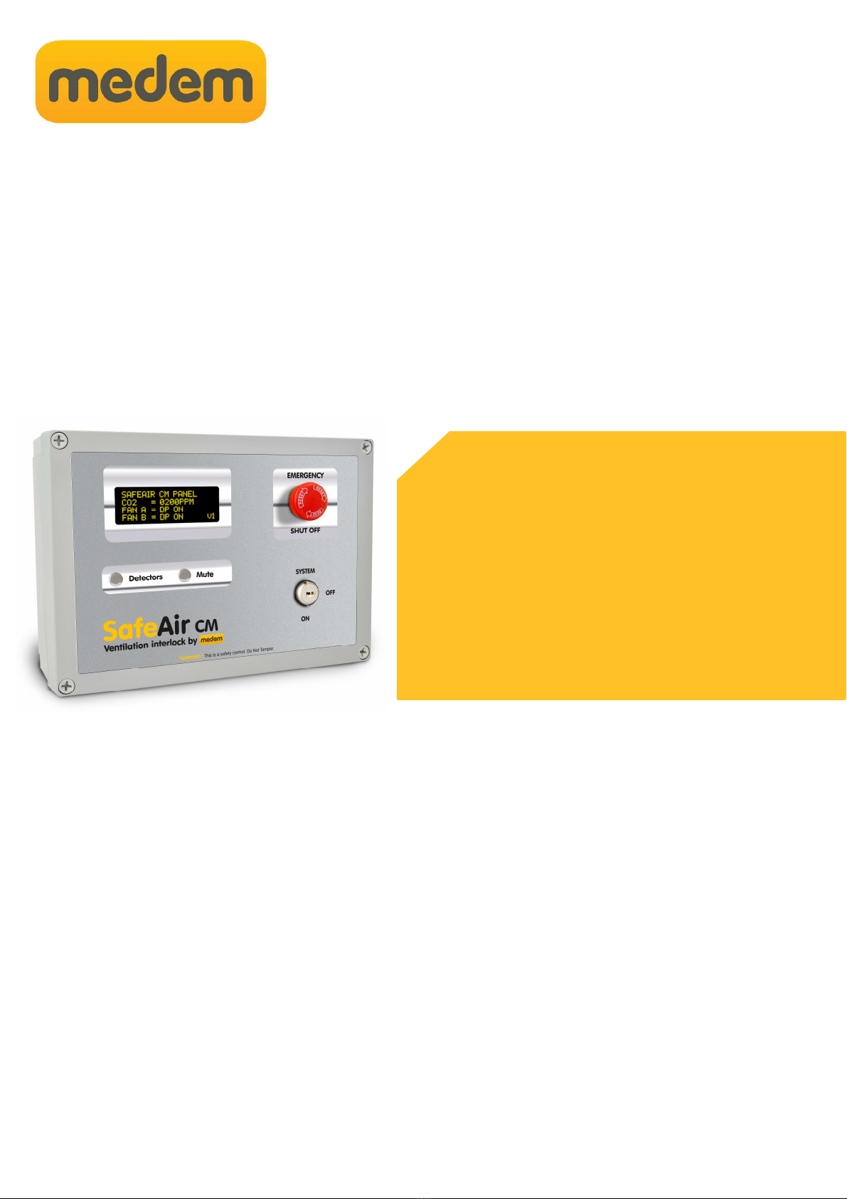
SafeAir CM
Installation Instructions
The SafeAir CM is a ventilation interlock with built in current monitoring and gas detection.
The system will ensure that any mechanical ventilation connected (supply and/or e tract) is running before
the gas can be used, when installed with gas sensors it will also monitor the atmosphere for CO and/or CO2.
It will then continually monitor for fan operation.
Before commencing installation please familiarise yourself to the equipment by reading the comprehensive
installation instructions. If in doubt then please call 0161 233 0600. Out of hours please call 07894 684080 or
07843 355163.
It is a statutory requirement that this safety system is installed and commissioned
to the satisfaction of the manufacturer.
A commissioning certificate must be issued to the end user along with instructions for the operation of the
equipment.
As the Manufacturer Medem UK should commission this safety system whereupon a commissioning report
will be forwarded to the installing agent who should provide a copy to the end user.
At the point of our commissioning an individual serial number will be attached to the system along with a 24
help line number. Photos and all relevant information for the installation will then be stored on the Medem
site database to be accessed in the event of a call on the 24 hour help line. The warranty period for the
panel and sender unit will then be e tended to Ten years.
• Gas Detection .(up to 4 detectors )
• Built in Fan Current Monitor for Fan interlocking.
• 5 year warranty - 10 years when commissioned
SafeAir CM features

2
08/03/2018
System description
SafeAir CM
System On/Off
Ventilation Interlock System For Kitchens
The SafeAir CM is a Ventilation Interlock with inbuilt two channel current monitor. The system will ensure that any mechanical
ventilation connected (supply or e tract) is running before the gas can be used. When installed with Medem gas detectors it will
also monitor the atmosphere for CO (Carbon Mono ide) and/or CO2 (Carbon Dio ide).
The system comprises of a mains powered panel capable of operating up to four sensors and internal two channel current
monitor for interlocking the mechanical ventilation with a monitoring range of 30 mAmps to 24 Amps.
The ventilation can also be interlocked by mechanical air flow switches (DP) if required.
Control Panel
The front of the panel has the following controls and indications:
Emergency stop button.
System On/Off switch.
Detectors button - For viewing detector status
Mute.
LCD display:
For displaying system status during both installation and normal use, also for displaying diagnostics

3
08/03/2018
Main features
SafeAir CM
Connections to panel: marked on board.
1. Live & Neutral 230 volts supply from 3amp switched fuse spur
2. 230 volts out to gas solenoid valve
3. Earth connection terminals
4. BMS to indicate, high alarm, gas on, EM stop, low alarm. (Using No14 AX1 & 2 )
00 = Gas On
01 = Fan Fault
10 = EM Stop & High Alarm
11 = Unused
5. Remote emergency stop buttons SELV, connect in series multiple buttons (requires a N/C circuit)
6. Power connections for detectors, Methane, LPG, CO, CO2, O ygen, Temperature
7. Comms connections for detectors, Methane, LPG, CO, CO2, O ygen, Temperature
9. 12 volt power
10. Fan A interlock for PD switches.
11. Fan B interlock for PD switches.
12. Fan A current monitor (CT) connection.
13. Fan B current monitor (CT) connection.
14. Fill & prove time for gas pressure proving & AUX relay settings (see No4).
15. Set Fan A to use either PD switch (No10) or Current Monitor (CT) (No12)
16. Lift valve button, opens the gas valve only whilst the button is continuously pressed, for commissioning purposes.
17. Display gas pressures on the LCD screen
18. Learn detectors button, press once only when all detectors are connected and powered. Also “learn Trip Current” when
pressed in conjunction with “No.19 Fan Comm” see page 4 for more details
19. Fan comm button: Displays the “Fan Current Trip level” this is the minimum fan current draw allowed before the system
will indicate that the fans aren’t running. (Default 35mA).
FAN A
FAN B
1 2
12
11
16 1
13
14
3 4 5 6 9 10
18 19
15
20
4
08/03/2018
Gas Detection
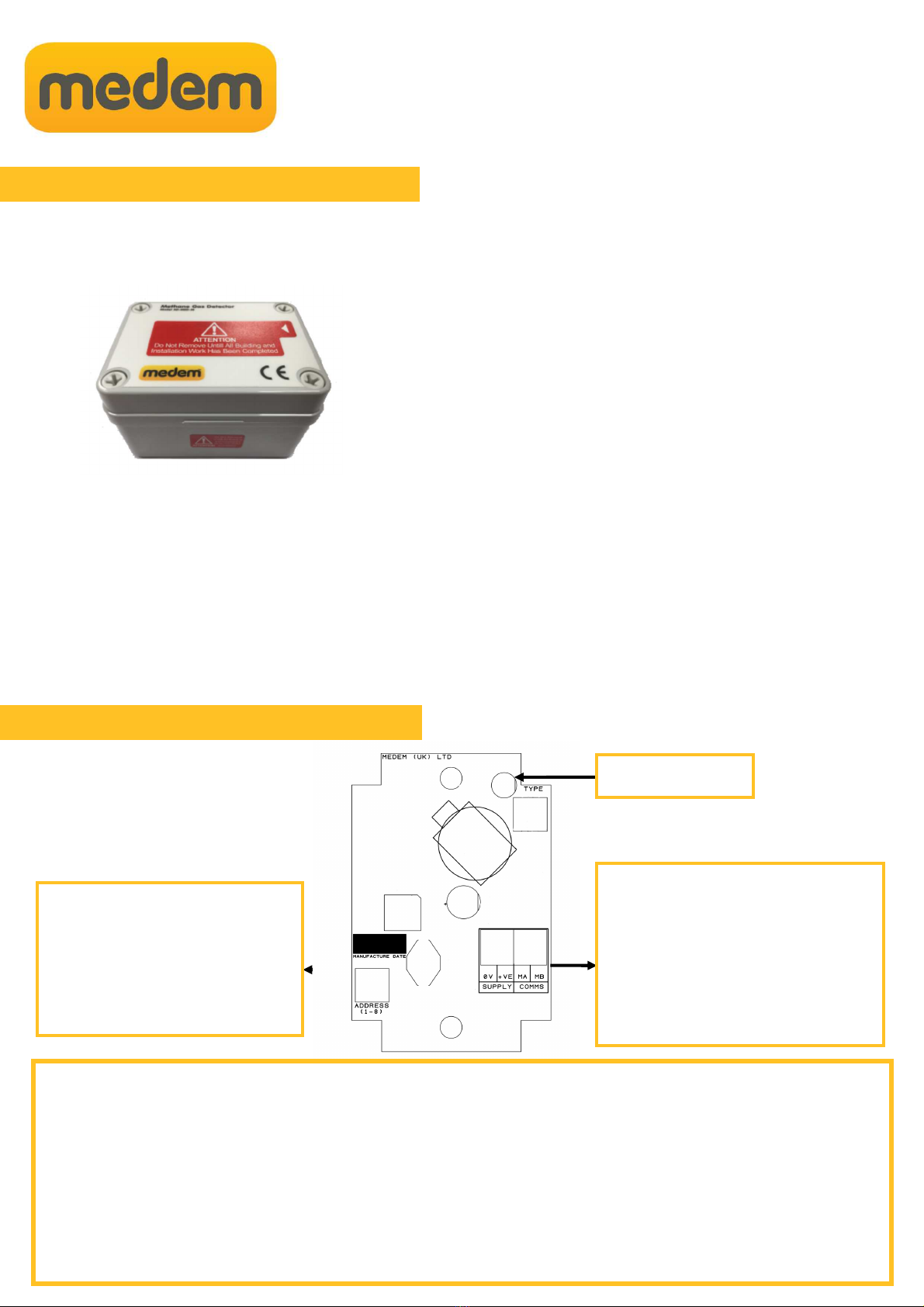
Gas Detectors
IMPORTANT - Gas Detectors should not be installed until all building, construction or painting work etc.. Is completed, as these
works can effect the sensitivity and longevity of the detectors.
Ensure that the protective cover labels (RED) are removed only
after the completion of all building work and the system has
been commissioned by the Medem engineer.
The labels are required to be removed for the detectors to
operate, but removal before the completion of works risks
contaminating the sensor element.
The system is capable of operating a mi of up to 4 detectors of different types.
Detector Alarm levels
Type Pre-Alarm High Alarm
CO: 80ppm 100ppm
CO2: 1800ppm 2800ppm
Pre-alarm will display a warning message and tone (3beeps) every 10mins.
High-alarm will display a warning message, tone every one second and isolate the gas valve after 60seconds.
Detector location will vary dependant on the individual characteristics of the target gas that is being monitored for. See the gas
detectors own instructions for more guidance.
Detector Information
Connection and addressing
+VE supply & Comm’s
From either the main panel or an
e tender.
Detectors are wired in parallel and can be
connected to one another daisy chain
Address Selector
Each detector must be set to its own
address (1-4) and then “learnt” using
button 18 (see page 3)
Status LED
SafeAir CM
All current wiring regulations must be followed with reference to running low and mains voltage cables together.
The ma imum cable length between a detector and the control panel should not e ceed 100 metres, if the distance between
the main panel and the detectors is greater than 20metres a 1mm screened cable must be used on the +VE, 0v terminals
Gas detectors, require a four core screened Belden type security cable or 600v rated BMS cable (ma cable length of
100meters.)
Pressure sender unit, remote emergency stops, require a two core screened cable.
Warranty will be void if Fire Protection Cable or cable over 1mm dia. is used on the SELV side.

5
08/03/2018
Detector Information
Detector location will vary dependant on the individual characteristics of the target gas that is being monitored for.
The descriptions below describe the position for each detector after considering these characteristics.
For proper function care must be taken not to site a detector in a “dead space” or in the flow of any ventilation.
Natural Gas/Methane
Natural gas detectors should be mounted at high level on a wall appro imately 150mm from the ceiling height and avoiding
corners and potential dead air areas.
Natural gas detectors should not be mounted below the height of the top of a doorway for e ample. This is because as the gas
is slightly lighter than air it will rise filling the room from the ceiling down and will spill through the top of a door opening into the
ne t room. If the detectors are mounted below this height then it will take longer the gas to reach the detector.
LPG /Propane
LPG gas is heavier than air so detectors need to be mounted at low level 100mm from the floor, consideration should be given
to any potential mopping or wet floor height.
Carbon Monoxide
Carbon Mono ide is similarly weighted to air so detectors should be mounted between 1 to 2 meters from the floor.
Carbon Dioxide
Carbon Dio ide detectors should be installed so they monitor the general level of CO2 within the area. They should be mounted
above standing head height and between 1m and 3m from the potential source. Care should be taken so they are not located
close to the edge of a canopy or in direct flow of the supply or e tract ventilation.
For additional information or guidance on site specific requirements please don’t hesitate to contact us.
Each detector has its own Bi-Colour LED which is used to indicate the status of that detector.
Not Lit: No power/comm’s. These a four wire units and all connections are required, check the polarity of both the
power and the comm’s (MA/MB) terminals are correct.
Flashing Green: Detector is warming up, the detectors will flash green on power up for 90 seconds while the sensor
elements stabilize. The system will ignore any detectors while flashing.
Solid Green: Detector is powered and active. Note: The detectors will still require correctly addressing (using the address
selector pot) and learning by the system using button 16 (see page 3).
Flashing Red: Low level alarm. All detectors have both a low and high level alarm, low level alarms serve as a warning
that an unsafe condition maybe building and gives chance to intervene before loss of gas service.
Solid Red High level alarm. An unsafe level of the target gas have been reached and the system will isolate the
gas supply. The cause of the alarm will require identifying and resolving before the gas supply can be re-
established.
After installation a simple bump test can be performed by using an appropriate level test gas in order to check operation. Full
testing and calibration checking takes place during a Medem commissioning.
Detector Location
Detector Indications
SafeAir CM

6
08/03/2018
Basic Connections
230v Supply
3Amp Fused Spur Medem
Gas detectors
Multiple,
connect in
parrallel
Earth Connections not shown
EM Stop Buttons,
Thermal links
(Normally closed)
For multiple, connect in
series.
Set a minimum fan running speed by setting a minimum allowed fan current load.
SafeAir CM
Fan speed
controls fans
12
13
15
11 10
Earth Connections not shown
Fan Supply
230 v
Where using 3 phase fans
interlock on a single phase
16 1 18 19
If you wish to set a minimum fan running speed, adjust the fans to the desired speed settings and then press buttons 19 & 18 together.
This will change the “minimum trip current” setting from the default 35mA to be that being used by the fans at your set speed.
Pressing button 19 (Fan comm) alone will display the new “minimum trip current” value. If the fan load drops below that level for more
than 10 seconds the system will give an alert and isolate the gas supply. There is a 20% allowance for fluctuations in fan load due to
temperature etc.
Fan A CT/PD to select between using CT 12 or Terminal 10 for PD switch.
Fan B CT/PD to select between using CT 13 or Terminal 11 for PD switch.
Fan B can be disabled/enabled using the Fan B DIS/EN selector.
Note: Fan A cannot be disabled, Fan A DIS/EN has no function.
Mains rating: 240/440 VAC 50HZ. Monitoring range - Min: 35 mAmps to Ma : 24 Amps Continuous.
Current Monitoring or PD Switch
No15

7
08/03/2018
Remote stop buttons
To EM Stop connections in the
panel
Use terminals TB2 A & C Use terminals TB2 A & C
Remote stop buttons can be connected to the panel terminal
marked as “EM STOP” (number 6 ).
The remote buttons must be wired as shown in order to provide a
“closed contact” for the control panel.
If thermal links are to be installed these should be wired
in series with the EM stop buttons
To EM Stop connections in the
panel
Indicator bar shows when
pressed
Normal EM-Stop Activated
Multiple Stop Buttons
Single Stop Buttons
Resetting (indicator bar)
The stop buttons supplied by Medem are of a “Push Glass, key resettable” style, when activated a yellow indicator bar will
show and the unit will require resetting using the key provided.
Multiple stop buttons are wired in series.
If thermal links are to be installed these too should
be wired in series with the EM stop buttons
Use terminal TB2 A & C
SafeAir CM

8
08/03/2018
Warranty
Medem (UK) Limited
Project House
19 Dallimore Road
Manchester
M23 9NX
Tel: (0) 161 233 0600
Fa : (0) 161 233 0601
Web: www.medem.co.uk
E-mail: sales@medem.co.uk
Medem UK Warranty
Terms & Conditions
1. The warranty is a parts warranty and Medem UK Ltd will not cover or accept any labour or
other e penses that may be incurred in the process of changing faulty product.
2. All panels and sender units are covered by a five year warranty.
3. Gas detector units and other remote detectors carry a two year warranty. Installation of the
detectors should not be undertaken until all building and construction work is completed.
4. Gas solenoid valves carry the original manufacturers warranty, though as the supplier
Medem UK will e change faulty valves for return to the manufacturer.
5. Where a Medem UK engineer (or another company appointed by Medem UK) commission
and installed system then that system will carry a ten year warranty. This applies to the
main panel and the sender unit. At the time of commissioning a security label with a serial
number will be attached to the main panel bo . photographs and a comprehensive record
of the installation will be held by Medem UK.
6. Where a warranty claim is made then, where appropriate, a written order to attend site
must be provided to Medem UK A cost for labour and travel to site will be prepared as a
quote. The cost must be included in the order.
7. Where it is found that the installation and/or the quality of workmanship has contributed to
or wholly caused the failure of the product then we reserve the right to charge the whole or
a proportion of the cost of the faulty item.
SafeAir CM

9
08/03/2018
messages
Detector fault, DXX lost comms
The system believes it has lost connection to a detector on address XX, verify detector addresses and press the “learn
button” (16). Verify all connected detectors are being registered by pressing “blind button B” (see page 2). If you have no
detectors connected to the system pressing the learn button will clear the error message.
Gas Off, Switch On Fan X.
The system can monitor the fan status via a current monitor or air pressure switches. These provide a closed contact to
terminals Fan A and Fan B, it is a requirement when using fan interlocking that the fans be running (and therefore the A and B1
receiving a closed contact) before the system can begin a gas pressure test. If at any point the fans stop running (opening the A
or B contact) the system will isolate the gas and report fans not running. Check that the fans are not only switched on, but
actually running and moving air.
Gas Off, Reset Em Stops & Switch On/Off
The system has an panel mounted emergency stop and connection inside for remote buttons. First check the panel button (once
pressed some require resetting by twisting and releasing). Clear the message by turning the main system switch off and then
back on, if the message remains check any remote buttons and their connections. The terminal for the remote buttons requires
a volt free normally closed contact, ensure all remote stop buttons, thermal links any another connected systems (BMS/Fire
panels) are reset and the contacts are closed.
In the event of any alert the system will always give a reason on screen as to the cause.
Common messages you may receive are shown below with further e planation.
If you require any help or if anything is unclear then please contact technical support on 0161 233 0600
SafeAir CM
Other manuals for SafeAir CM
1
Other Medem Measuring Instrument manuals


Popular Measuring Instrument manuals by other brands


 instruction manual")


WILGER
WILGER EFMS Installation and operation manual

Mirion Technologies
Mirion Technologies RDS-32 quick guide

Keithley
Keithley SourceMeter 2600B Series quick start guide

Levenhuk
Levenhuk Ermenrich Verk LL60 Digital Level user manual

Guildline
Guildline 6675A Technical manual

MICRO-EPSILON
MICRO-EPSILON surfaceCONTROL 3D 35 Series Assembly instructions


