Medem SafeSpace M User manual

27/04/2017
SafeSpace M
Please read this sheet as it contains
important information
Before commencing installation please familiarise yourself to the
equipment by reading the comprehensive installation instructions. If
in doubt then please call 01 1 233 0 00.
It is a statutory requirement that this safety system is installed and
commissioned to the satisfaction of the manufacturer.
A commissioning certificate must be issued to the end user along
with instructions for the operation of the equipment.
As the Manufacturer Medem UK should commission this safety
system whereupon a commissioning report will be forwarded to the
installing agent who should provide a copy to the end user.

27/04/2017
SafeSpace M
Four Channel
Gas Monitoring System
The SafeSpace M is a gas detection system, it can monitor the atmosphere for
natural gas (CH4 & LPG), CO, CO2 and Oxygen Depletion when fitted with the
appropriate Medem detectors.
In the event of a high alarm from one of the sensors the system will alarm. Any
connected remote beacons and sounders would then be activated..
The system will automatically restart after a power failure.
The system comprises of a mains powered panel capable of monitoring up to four
sensors. The sensors, purchased separately are pre-calibrated by Medem (UK) Ltd
such that they only require to be addressed then connected to the panel and
functionally tested.

27/04/2017
SafeSpace M
Technical data sheet
The model SafeSpace M consists of a mains powered panel capable of operating up to four detectors.
The system will automatically restart after a power failure.
The detectors are connected by low voltage 4 core cable (typically beldon cable) back to the control panel.
The detectors may be mounted up to 100mtrs from the control unit.
The complete system is designed to comply with the latest CE directives including the low voltage directive.
This is housed in an IP 5 rated ABS enclosure measuring 180mm high x 129mm wide x 70mm deep.
Relay outputs:
SELV relay rated at 48volts to activate a remote sounder/beacon or signal a BMS system.
The aux relay function depends on the setting of the “Aux RLY” DIP Switches - this is a dynamic (non-latching) relay.
This can advise a BMS of any one of the following conditions.
AX1 - AX2
Off - Off = High Alarm
On - Off = Unused
Off - On = Unused
On - On = Detector Fault
Gas Detector Types
AD-MED-CO Carbon Monoxide Detector (CO)
AD-MED-CO2 Carbon Dioxide Detector (CO2)
AD-MED-M Natural Gas Detector (Methane) (CH4)
AD-MED-LPG Natural Gas Detector (Propane) (LPG)
AD-MED–OXY Oxygen Depletion Detector (O2)
Detector Alarm levels
Type Pre-Alarm High Alarm
CO: 80ppm 100ppm
CO2: 2800ppm 5000ppm
CH4/LPG 5% 10%
OXY-DEP 19.5% 18%
All current wiring regulations must be followed with reference to running low and mains voltage cables together.
The maximum cable length between a detector and the control panel should not exceed 100 metres, if the distance between
the main panel and the detectors is greater than 20metres a 1mm screened cable must be used on the +VE, 0v terminals
Gas detectors, require a four core screened Belden type security cable or 00v rated BMS cable (max cable length of
100meters.)
Remote emergency stops and thermal links require a two core screened cable.
Warranty will be void if Fire Protection Cable or cable over 1mm dia. is used on the SELV side.

27/04/2017
SafeSpace M
1 2
12 11
1
17
13
14
3 4 5 7 8 9 10
18
19
20
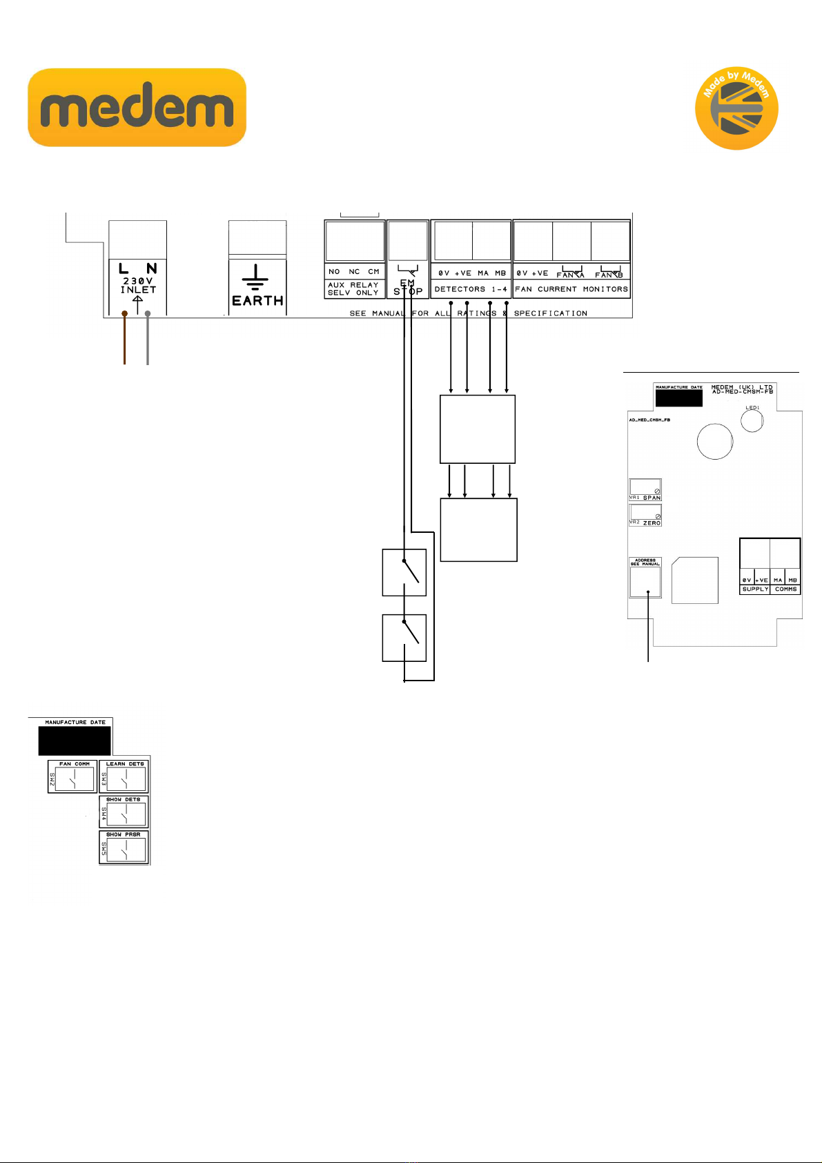
Connections to panel: marked on board.
1. Live & Neutral 230 volts supply from 3amp switched fuse spur
2. 230 volts out to gas solenoid valve
3. Earth connection terminals
4. BMS to indicate, high alarm, gas on, EM stop, low alarm. (Using No13 AX1 & 2 )
00 = EM Stop & High Alarm
10 = Unused
01 = Gas On
11 = Detector Fault
5. Remote emergency stop buttons SELV, connect in series multiple buttons (requires a N/C circuit) - Thermal links and Fire
Alarm can also be connected in series
. Power connections for detectors, Methane, LPG, CO, CO2, Oxygen, Temperature
7. Comms connections for detectors, Methane, LPG, CO, CO2, Oxygen, Temperature
8. 12 volt power for current monitor (CM2M-K)
9. Fan A interlock for current monitor (CM2M-K) or PD switches.
10.Fan B interlock for current monitor (CM2M-K) or PD switches.
11. Jumper link to disable audible alarm sounder.
12. Header socket for front panel key switch.
13. AUX relay settings (see No4).
14. Header socket for front panel Mute button.
1 . Learn detectors button, press once only when all detectors are connected and powered
17. View detectors
18. Display gas pressures on the LCD screen
27/04/2017
SafeSpace M
Installing gas detectors
Gas detectors are wired via a four core low voltage cable into terminals marked & 7. The detectors must
have their “address id selector switch” set to the addresses 1-4.
CO detectors must be number addressed before natural gas detectors.
Once connected and addressed the system must be “taught” which detector types are on which address.
This is done by pressing button marked 1 ‘Learn Dets’. The system will beep to confirm the action.
Pressing No 17 will display detector addresses 1 &2, pressing 17 & 18 together will display addresses 3 & 4.
Detector Fault DXX Lost Comms
If the system displays a message “Detector Fault DXX Lost Comms” the system is informing you that a
detector which has been previously “learnt” to address DXX is no longer communicating. This could be
because the detector has had its address changed or has been removed. In which case “re-learning” using
button 17 will correct the addressing.
If the detector is present, but not being seen by the system on its address channel, then check the wiring
between the main control panel and detector.
1
17
1 3 4 5 7 8 9 10
18
Connect in
parallel
3 amp fused spur
230v
EM Stop Buttons,
TT-70c heat detectors &
Fire Alarm Input
Series connected
Addressable
Gas
Detectors
2
Example Medem Gas Detector
Address selector switch: use 1 to 4 only

27/04/2017
SafeSpace M
It is essential that the installation of the system is carried out in the order given
below to ensure the correct operation of the system.
This guide, when completed, should be posted to Medem UK in order that the
warranty period can be activated.
Site Name
Installing ompany
Engineers Name
Date ompleted
Tick as each step is completed
1: All wiring checked tight and connected
as per the installation instructions.
2: Each detector has an individual number
from adjusting the rotary switch before the
“learn” button was pressed.
3: All detectors have a solid green LED
Illuminated when not in alarm.
4: Each detector has been recognised by
the panel.
5: On applying test gas to the
detectors the LED turns red
and the panel alarms and closes the
gas valve.
With the panel fitted to the wall the following steps should be
followed.
1. Connect BMS, beacons, sounders etc to the
relay outputs.
2. Connect any additional EM stop buttons and
thermal links in series to the terminals marked
“EM STOP”.
3. Each detector has a rotary address switch and
each switch should be set to a different number
starting with “1”. Then connect the gas detectors
to terminals marked “detectors” on the panel.
Detectors can be wired “Daisy chain”.
4. Connect the 3 amp fused spur 240 volt supply to
marked terminals and switch on.
5. Press the “learn dets button” this is on the main
circuit board in the top right corner. Pressing this
once allows the panel to learn how many and
which type of detectors are fitted.
6. Once power is connected to the panel the
detectors will flash the green LED’s for 90
seconds after which the LED’s will be on
continuously.
Return one copy of this sheet to the address below:
Manufactured by:
Medem (UK) Limited
Project House, 19 Dallimore Road, Roundthorn Industrial Estate,
Manchester, M23 9NX
Tel: +44 (0) 6 233 0600
Fax:+44 (0) 6 233 060
Please do not hesitate to call for advice on the
following numbers:
0161 233 0600 office hours
Detector type Methane CO LPG
Number fitted
Other Medem Measuring Instrument manuals


Popular Measuring Instrument manuals by other brands

red lion
red lion CUB5R manual

Electronics International Inc
Electronics International Inc M-1 Operating and installation instructions

Midwest
Midwest Delta Meter 142 Installation and operating instructions

POTOMAC INSTRUMENTS INC.
POTOMAC INSTRUMENTS INC. PI 4100 user guide

Electronics International Inc
Electronics International Inc SR-8A Operating and installation instructions

Flocorp
Flocorp UltraFlo UFD3 user manual


