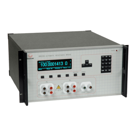
Guildline 6675A User manual

VOLUME I
TECHNICAL MANUAL
FOR
MODEL 6675A
AUTOMATIC DIRECT-CURRENT-COMPARATOR
RESISTANCE BRIDGE
NOTICE
The contents and information contained in this manual are proprietary to
Guildline Instruments. They are to be used only as a guide to the operation
and maintenance of the equipment with which this manual was issued and may
not be duplicated or transmitted by any means, either in whole or in part,
without the written permission of Guildline Instruments.
VOL I TM6675A-C-00
January 30, 2001

i
TABLE OF CONTENTS
1. INTRODUCTION.......................................................................................................1-1
1.1. MODEL 6675A AUTOMATIC DIRECT-CURRENT-COMPARATOR RESISTANCE BRIDGE
GENERAL DESCRIPTION...........................................................................................................................................1-1
1.2. PANEL FRONT TERMINALS/CONTROLS..............................................................................................1-1
1.2.1. Reference Resistor Input Terminals..........................................................................................................1-1
1.2.2. Resistor Under Test Input Terminals........................................................................................................1-1
1.2.3. Numeric Keypad........................................................................................................................................1-1
1.2.4. Special Keys..............................................................................................................................................1-2
1.2.4.1. Cursor Movement Keys. ......................................................................................................................1-2
1.2.4.2. Function Keys.......................................................................................................................................1-2
1.2.5. Display.......................................................................................................................................................1-2
1.2.6. High Voltage Out Terminals.....................................................................................................................1-2
1.2.7. Program Out Terminals.............................................................................................................................1-2
1.2.8. Extender In Terminals...............................................................................................................................1-3
1.2.9. Ground Terminals......................................................................................................................................1-3
1.2.10. Guard Terminals........................................................................................................................................1-3
1.3. REAR PANEL CONNECTORS/CONTROLS.............................................................................................1-4
1.3.1. Chart Recorder Output..............................................................................................................................1-4
1.3.2. IEEE-488 Interface....................................................................................................................................1-4
1.3.3. RS232 Interface.........................................................................................................................................1-4
1.3.4. Sync Output...............................................................................................................................................1-4
1.3.5. Line Input Voltage Selector. .....................................................................................................................1-4
1.3.6. Line Input Connector. ...............................................................................................................................1-4
1.3.7. Power Switch.............................................................................................................................................1-5
2. PERFORMANCE SPECIFICATIONS.......................................................................2-1
2.1. GENERAL SPECIFICATIONS .....................................................................................................................2-1
2.2. GENERAL SPECIFICATIONS (continued) ................................................................................................2-2
2.3. RESISTANCE MEASUREMENT SPECIFICATIONS..............................................................................2-3
2.4. TEMPERATURE MEASUREMENT SPECIFICATION..........................................................................2-4
3. OPERATING INSTRUCTIONS.................................................................................3-1
3.1. PRELIMINARIES............................................................................................................................................3-1
3.1.1. Rackmount Bracket...................................................................................................................................3-1
3.2. WARNING.........................................................................................................................................................3-2
3.3. OPERATING PROCEDURE..........................................................................................................................3-4
3.4. GENERAL KEY/DISPLAY OPERATIONS................................................................................................3-7
3.4.1. Base Menu.................................................................................................................................................3-7
3.4.1.1. Base Menu Display. .............................................................................................................................3-7

ii
3.5. BASIC MENU OPERATIONS.......................................................................................................................3-8
3.5.1. Menu Option - <MEASURE>..................................................................................................................3-8
3.5.2. Menu Option - <any other menu but measure>........................................................................................3-9
3.5.3. Base Edit/Select Menu - one column of data..........................................................................................3-10
3.5.4. Base Edit/Select Menu - two columns of data........................................................................................3-10
3.5.5. Operation of Select/Edit Data Menus .....................................................................................................3-10
3.5.5.1. Function - <Screen ?>........................................................................................................................3-10
3.5.5.2. Function - <Select>............................................................................................................................3-11
3.5.5.3. Function - <Ok>.................................................................................................................................3-11
3.6. TITLE SCREEN .............................................................................................................................................3-12
3.7. MAIN MENU...................................................................................................................................................3-13
3.7.1.1. <Measure> MENU Fn-1 (MAIN) Page 1 of 3..................................................................................3-14
3.7.1.2. <Measure> MENU Fn-1 (MAIN) Page 2 of 3..................................................................................3-16
3.7.1.3. <Measure> MENU Fn-1 (MAIN) Page 3 of 3..................................................................................3-17
3.7.2. <Setup> MENU Fn-2 (MAIN)..............................................................................................................3-18
3.7.2.1. <Load> MENU Fn-1 (Setup_MAIN)................................................................................................3-18
3.7.2.2. <Edit> Resistors MENU Fn-2 ...........................................................................................................3-20
3.7.2.3. <Save> MENU Fn-3 (Resistors_Setup_MAIN)...............................................................................3-32
3.7.3. <Voltmeter> MENU Fn-1 (MAIN)........................................................................................................3-34
3.7.4. <Sofcal> MENU Fn-4 (MAIN)..............................................................................................................3-36
3.7.4.1. <GPIB> MENU Fn-1 (Sofcal_MAIN)..............................................................................................3-37
3.7.4.2. <RS232> MENU Fn-2 (Sofcal_MAIN)............................................................................................3-38
3.7.4.3. <Voltmeter> MENU Fn-3 (Sofcal_MAIN).......................................................................................3-40
3.7.4.4. <Diagnostic> MENU Fn-1 (Sofcal_MAIN) .....................................................................................3-42
3.7.4.5. <Selftest> MENU Fn-2 (Sofcal_MAIN)...........................................................................................3-45
3.7.4.6. <Chart> MENU Fn-3 (Sofcal_MAIN)..............................................................................................3-46
3.7.4.7. <Filter> MENU Fn-1 (Sofcal_MAIN) ..............................................................................................3-47
3.7.4.8. <Datum> MENU Fn-2 (Sofcal_MAIN)............................................................................................3-47
3.7.4.9. <PASSWORD> MENU Fn-3 (Sofcal_MAIN).................................................................................3-48
3.8. MEASUREMENT OPERATION GUIDE ..................................................................................................3-49
3.8.1. Introduction .............................................................................................................................................3-49
3.8.2. Resistance Measurement Normal Ohms - 1 mRs10 k............................................................3-49
3.8.2.1. General Procedures.............................................................................................................................3-52
3.8.3. Resistance Measurement - High Ohms - 100 kRs100 M; Rx 1 G....................................3-56
3.8.3.1. High Ohms Measurements - General Procedures..............................................................................3-56
3.8.4. Resistance Measurement - Low Ohms. ..................................................................................................3-61
3.8.4.1. General Procedures Using Guildline High Current Range Extenders..............................................3-62
3.8.5. Thermometry Measurements. .................................................................................................................3-65
3.8.6. Summary of Recommended Test Setups................................................................................................3-67
3.9. 6675A DATA ACQUISITION SOFTWARE..............................................................................................3-69
4. THEORY OF OPERATION.......................................................................................4-1
4.1. THEORY I INTRODUCTION.......................................................................................................................4-1
4.1.1. The automatic direct-current-comparator resistance bridge.....................................................................4-2
4.1.1.1. The manual bridge - background.........................................................................................................4-2
4.1.2. The automatic bridge.................................................................................................................................4-3
4.1.3. Automatic direct-current-comparator bridge balance...............................................................................4-5
4.2. THEORY II RESISTANCE MEASUREMENT - 9975 BACKGROUND................................................4-8
4.2.1. Theory II 6675A........................................................................................................................................4-9
4.2.2. 6675A Servo Circuit................................................................................................................................4-13

iii
4.2.3. 6675A Primary Current Ix.......................................................................................................................4-13
4.2.3.1. Low-Measurement Mode...............................................................................................................4-13
4.2.3.2. Normal-Measurement Mode..........................................................................................................4-14
4.2.3.3. High-Measurement Mode..............................................................................................................4-14
4.2.4. 6675A Signal Acquisition.......................................................................................................................4-17
4.2.5. 6675A Measurement Cycle - 4-Terminal "Normal-".........................................................................4-19
4.2.6. Graphical Representation of Turns Switching and nV readings............................................................4-21
4.3. NANOVOLT DETECTOR CPU OPTIONS...............................................................................................4-23
4.3.1. Dip Switches............................................................................................................................................4-23
4.3.1.1. Option Switch 1 - 50/60 Hz Select.....................................................................................................4-23
4.3.1.2. Option Switches 2 to 8 - ADC Beta...................................................................................................4-23
4.3.2. Nanovolt Detector Principles of Operation. ...........................................................................................4-24
4.3.2.1. Introduction. .......................................................................................................................................4-24
4.3.2.2. Nanovolt Detector Power Supply (19103.01.02)..............................................................................4-24
4.3.2.3. Nanovolt Detector CPU PCB (19855.01.02).....................................................................................4-24
4.3.2.4. Analog Interface.................................................................................................................................4-25
4.3.2.5. Central Processing Unit......................................................................................................................4-25
4.3.2.6. Memory ..............................................................................................................................................4-26
4.3.2.7. Serial Fibre-Optic Communication Interface.....................................................................................4-26
4.3.2.8. Gpib Interface.....................................................................................................................................4-26
4.3.3. Analog To Digital (A/D) Converter (19502.01.02)................................................................................4-26
4.3.3.1. Voltage To Current (V/I) Converter. .................................................................................................4-28
4.3.3.2. High Speed Low Noise Current Buffer. ............................................................................................4-28
4.3.3.3. Precision References. .........................................................................................................................4-28
4.3.3.4. Precision Current Sink........................................................................................................................4-28
4.3.3.5. Current Mode Switch.........................................................................................................................4-28
4.3.3.6. Start/Stop Integrator Switch...............................................................................................................4-28
4.3.3.7. The Integrator.....................................................................................................................................4-29
4.3.3.8. Charge Balance Sampler....................................................................................................................4-29
4.3.3.9. Master Clock.......................................................................................................................................4-29
4.3.3.10. Conversion Timer..........................................................................................................................4-29
4.3.3.11. Interconversion Pause. ..................................................................................................................4-29
4.3.3.12. A/D Trigger...................................................................................................................................4-30
4.3.3.13. 12 BIT A/D Converter...................................................................................................................4-30
4.3.4. Nanovolt Detector Input Amplifier PCB (19503.01.02)........................................................................4-30
4.3.4.1. High Input Impedance Low Noise Amplifier....................................................................................4-30
4.3.4.2. Input And Range Selection. ...............................................................................................................4-31
4.3.4.3. Charge Pump......................................................................................................................................4-31
4.3.4.4. Attenuator...........................................................................................................................................4-31
4.3.4.5. Power Supplies...................................................................................................................................4-31
4.3.4.6. Overload Protection............................................................................................................................4-31
4.3.5. Nanovolt Detector Software....................................................................................................................4-32
5. REMOTE CONTROL................................................................................................5-1
5.1. INTERFACES...................................................................................................................................................5-1
5.2. IEEE-488 (GPIB) INTERFACE .....................................................................................................................5-1
5.2.1. Controller...................................................................................................................................................5-2
5.2.2. IEEE-488 Responses.................................................................................................................................5-2
5.2.3. Interconnecting Cable And IEEE-488 Connector....................................................................................5-2
5.2.4. Typical System..........................................................................................................................................5-2
5.2.5. Address And Talk/Listen Selection. .........................................................................................................5-3
5.2.6. IEEE-488 Electrical Interface. ..................................................................................................................5-3
5.2.7. IEEE-488 Input Buffering.........................................................................................................................5-3

iv
5.2.8. IEEE-488 Output Buffering......................................................................................................................5-5
5.2.9. IEEE-488 Deadlock...................................................................................................................................5-5
5.3. RS232C INTERFACE......................................................................................................................................5-6
5.3.1. RS232C - Pin Designations.......................................................................................................................5-7
5.3.2. RS232C Responses. ..................................................................................................................................5-7
5.4. COMMAND LANGUAGE..............................................................................................................................5-8
5.4.1. General Syntax For Commands................................................................................................................5-8
5.4.2. General Syntax For Numbers....................................................................................................................5-8
5.5. REMOTE AND LOCAL OPERATION........................................................................................................5-8
6. CALIBRATION..........................................................................................................6-1
6.1. TEST EQUIPMENT.........................................................................................................................................6-1
6.2. RATIO 1:1 Using Model 9330 / 1 to Model 9330 / 1 ............................................................................6-1
6.3. RATIO 1:1 Using Model 9330 / 10 kto Model 9350 / (10 kConfiguration).....................................6-1
6.4. RATIO 10:1........................................................................................................................................................6-2
1.1.1. Model 9330 /10 kto Model 9350 /(100 kConfiguration) .................................................................6-2
6.4.2. Model 9350 /(1K Configuration) to Model 9330 /10 k....................................................................6-2
6.5. RATIO 1:1..........................................................................................................................................................6-1
6.5.1. Model 9330 /100 Mto Model 9330 /100 M.......................................................................................6-1
7. MAINTENANCE........................................................................................................7-1
7.1. INTRODUCTION.............................................................................................................................................7-1
7.1.1. Error Messages..........................................................................................................................................7-1
7.1.2. 6675A Warnings. ......................................................................................................................................7-2
7.1.3. Nanovolt Detector Calibration..................................................................................................................7-3
7.1.3.1. Introduction. .........................................................................................................................................7-3
7.1.3.2. Nanovoltmeter Calibration...................................................................................................................7-3
7.1.3.3. ADC Beta. ............................................................................................................................................7-4
7.1.4. Disassembly Procedure.............................................................................................................................7-5
7.1.4.1. Cover Removal Procedure. ..................................................................................................................7-5
7.1.4.2. Primary Current Drive Module (19327) Removal Procedure.............................................................7-5
7.1.4.3. Servo-loop Module (19328) Removal Procedure................................................................................7-6
7.1.4.4. PDCC Comparator Module (19121) Removal Procedure...................................................................7-7
7.1.5. Reassembly Procedure ..............................................................................................................................7-8
7.2. TROUBLESHOOTING...................................................................................................................................7-8
7.2.1. Introduction ...............................................................................................................................................7-8
7.2.2. Power Up...................................................................................................................................................7-8
7.2.3. Power Supply Check.................................................................................................................................7-9
7.2.3.1. Primary Current Drive Power Supply PCB Test Procedure................................................................7-9
7.2.3.2. Servo Loop Power Supply PCB Test Procedure...............................................................................7-10
7.2.3.3. Nanovolt Dual Power Supply PCB Assy 19334 Test Procedure......................................................7-11
7.2.3.4. 6675A CPU and Display Power Supply PCB Test Procedure..........................................................7-12
7.2.4. Alignment Procedure..............................................................................................................................7-12
7.2.4.1. Alignment Test Equipment Required ................................................................................................7-12
7.2.4.2. Initial Checks......................................................................................................................................7-13

v
7.2.4.3. Primary Current Drive Adjustments (Board 19108) .........................................................................7-13
8. PARTS LISTS - MODEL 6675A...............................................................................8-1
9. DRAWINGS - MODEL 6675A...................................................................................9-1

vi
LIST OF FIGURES
FIGURE 1-1 : FRONT PANEL CONTROLS..................................................................................................................1-3
FIGURE 1-2 : REAR PANEL CONTROLS ....................................................................................................................1-5
FIGURE 3-1 : LINE VOLTAGE SELECTOR.................................................................................................................3-3
FIGURE 3-2: MENU TREE - SETUP/MEASURE.........................................................................................................3-5
FIGURE 3-3: MENU TREE - SOFCAL/VOLTMETER.................................................................................................3-6
FIGURE 3-4 : FRONT PANEL CONNECTIONS - NORMAL OHMS.......................................................................3-50
FIGURE 3-5 : RECOMMENDED GUARDING FOR NORMAL OHMS ..................................................................3-51
FIGURE 3-6 : FRONT PANEL CONNECTIONS HIGH OHMS - EXTERNAL HV SUPPLY................................3-57
FIGURE 3-7 : FRONT PANEL CONNECTIONS HIGH OHMS - INTERNAL HV SUPPLY .................................3-58
FIGURE 3-8 : RECOMMENDED GUARDING FOR HIGH RESISTANCE MODE................................................3-59
FIGURE 3-9 : FRONT PANEL CONNECTIONS LOW OHMS, 6623 RANGE EXTENDER.................................3-64
FIGURE 4-1 : DIRECT-CURRENT-COMPARATOR BRIDGE...................................................................................4-3
FIGURE 4-2 : AUTOMATIC DCC BRIDGE BALANCE .............................................................................................4-5
FIGURE 4-3 : BLOCK DIAGRAM 9975, 4-WIRE MEASUREMENT ......................................................................4-11
FIGURE 4-4 : BLOCK DIAGRAM 6675A ...................................................................................................................4-12
FIGURE 4-5 : 6675A SERVO "IS".................................................................................................................................4-15
FIGURE 4-6 : 6675A PRIMARY CURRENT "IX".......................................................................................................4-16
FIGURE 4-7 : 6675A MEASUREMENT CYCLE ........................................................................................................4-20
FIGURE 4-8 : 6675A TURN SWITCHING AND NV READING GRAPHICAL REPRESENTATION.................4-22
FIGURE 4-9 : NANOVOLT DETECTOR CPU OPTION SWITCH LOCATION....................................................4-23
FIGURE 4-10 : CHARGE BALANCE A/D CONVERTER........................................................................................4-27

vii
LIST OF TABLES
TABLE 2-1 : GENERAL SPECIFICATIONS.................................................................................................................2-1
TABLE 2-2 : GENERAL SPECIFICATIONS (CONTINUED) .....................................................................................2-2
TABLE 2-3 : RESISTANCE MEASUREMENT SPECIFICATIONS...........................................................................2-3
TABLE 2-4 : TEMPERATURE MEASUREMENT SPECIFICATIONS......................................................................2-4
TABLE 3-1 : 4-TERMINAL MODE TEST SETUP.....................................................................................................3-67
TABLE 3-2 : 2-TERMINAL MODE TEST SETUP......................................................................................................3-68
TABLE 3-3 : LOW OHM MODE TEST SETUP ..........................................................................................................3-68
TABLE 4-1 : NANOVOLT DETECTOR CPU OPTION SWITCHES........................................................................4-23
TABLE 5-1 : IEEE488 CONNECTOR PIN DESIGNATIONS......................................................................................5-4
TABLE 5-2 : IEEE488 DEVICE CAPABILITIES..........................................................................................................5-5
TABLE 5-1 : RS232 CONNECTOR PIN DESIGNATIONS..........................................................................................5-7
TABLE 7-1 : 6675A ERROR MESSAGES......................................................................................................................7-1
TABLE 7-1 : 6675A WARNINGS ...................................................................................................................................7-2
TABLE 7-1 : TEST POINT VOLTAGES ASSEMBLY 19108......................................................................................7-9
TABLE 7-1 : TEST POINT VOLTAGES ASSEMBLY 19107....................................................................................7-10
TABLE 7-1 : TEST POINT VOLTAGES ASSEMBLY 19334....................................................................................7-11
TABLE 7-1 : TEST POINT VOLTAGES POWER SUPPLY ASSEMBLY 19473 ....................................................7-12
TABLE 7-1 : REFERENCE VOLTAGES......................................................................................................................7-30

Section 1
1-1
1. INTRODUCTION
1.1. MODEL 6675A AUTOMATIC DIRECT-CURRENT-COMPARATOR
RESISTANCE BRIDGE GENERAL DESCRIPTION
This document describes the preliminaries to setup and use the Guildline Model 6675A Automatic
Direct-Current-Comparator Resistance Ratio Bridge.
1.2. PANEL FRONT TERMINALS/CONTROLS
The 6675A front panel controls are shown in Figure 1-1.
1.2.1. Reference Resistor Input Terminals
The reference resistor input terminals consist of 4 low thermal copper binding posts. The
binding posts have the ‘Rs’ label inside the group of four posts. The posts are labeled from
left to right, ‘C1’, ‘P1’, ‘P2’, and ‘C2’. A 2 meter, 4 conductor cable set with guard wire, is
provided in the 6675A Spare Parts Kit, Guildline part number 19543.01.02, for connection
to these terminals.
1.2.2. Resistor Under Test Input Terminals.
The resistor under test input terminals consist of 4 low thermal copper binding posts. The
binding posts have the ‘Rx’ label inside the group of four posts. The posts are labeled from
left to right, ‘C1’, ‘P1’, ‘P2’ and ‘C2’. A 2 meter, 4 conductor cable set with guard wire, is
provided in the 6675A Spare Parts Kit, Guildline part number 19543.01.02, for connection
to these terminals.
1.2.3. Numeric Keypad.
The numeric keypad consists of 15 keys. The key list contains the following; <0>, <1>,
<2>, <3>, <4>, <5>, <6>, <7>, <8>, <9>, <->, <.>, <CLEAR>, <E>, <LOAD>.

Section 1
1-2
1.2.4. Special Keys.
1.2.4.1.Cursor Movement Keys.
The cursor movement keys consist of 4 keys, <LEFT ARROW>,<UP
ARROW>,<DOWN ARROW> and <RIGHT ARROW>
1.2.4.2.Function Keys.
The function keys consist of four unlabelled keys located below the display. The
function of these four keys are variable and can take on any of the "soft" functions
described in section 3.4 of this manual. In addition to the "soft" function keys are
two keys fixed function keys <PREVIOUS> and <CANCEL>. Pressing the
<PREVIOUS> key returns control to the previous menu level, above the currently
selected menu. Pressing the <CANCEL> key will undo any keypad entry changes
that have been made.
1.2.5. Display.
The green vacuum fluorescent graphic display is a combined 256 x 64 pixel graphic display
and an 8 line by 42 column character display.
1.2.6. High Voltage Out Terminals.
The High Voltage Output Terminal is a blue four way binding post located on the sloped
part of the front panel, on the far left side. The output from this terminal can be used to
provide the test current when measuring two terminal high value resistances. A 1 meter
single conductor, high voltage cable is provided in the 6675A Spare Parts Kit, Guildline
part number 19543.01.02. for connection to this terminal.
1.2.7. Program Out Terminals.
The Program Out Terminals consist of 2 four way binding posts, one black and one red.
These terminals can be used when a reversing switch external to the 6675A is to be used to
control the test voltage for a two terminal high value resistance measurement. The signal
low terminal is referenced to the Rx input. An optional 1.5 meter, double banana plug,
cable set is offered as Guildline part number 996-00122, for connection between these
terminals and the reversing switch.

Section 1
1-3
1.2.8. Extender In Terminals.
The Extender In Terminals consist of 2 four way binding posts, one black and one red, the
middle two terminals in the group of 6. These terminals can be used when low values of
resistance are to be measured using an external current range extender. An optional 1.5
meter, double banana plug, cable set is offered as Guildline part number 996-00122, for
connection between these terminals and the range extender.
1.2.9. Ground Terminals.
The Ground Terminal consists of 1 green four way binding post. The bottom terminal in
the group of 6. This terminal provides a suitable termination point when a single safety
ground is required in the measurement cabling. A signal low terminal referenced to the Rs
input resistor is provided along side the safety ground terminal. See figure 3-5 for the
recommended connections for these terminals. The low thermal cable set provided with the
6675A Spare Parts Kit (Guildline part number 19543.01.02) includes wires for connection
to the ground terminals.
1.2.10. Guard Terminals.
The Guard Terminals consist of 2 white four way binding posts. Two guard points are
provided, one guard is referenced to the signal high side of the four terminal Rx resistor and
the other to the signal high side of the four terminal Rs resistor. See figure 3-5 for the
recommended connections for these terminals. The low thermal cable set provided with the
6675A Spare Parts Kit (Guildline part number 19543.01.02) includes wires for connection
to the guard terminals.
Figure 1-1 : Front Panel Controls

Section 1
1-4
1.3. REAR PANEL CONNECTORS/CONTROLS
The 6675A rear panel controls are shown in Figure 1-2.
1.3.1. Chart Recorder Output.
The Chart Recorder Output connectors consist of 2 four way binding posts, one black
terminal and one red terminal with a full scale output of ±5 volts. An optional 1.5 meter,
double banana plug, cable set is offered as Guildline part number 996-00122, for
connection between these terminals and the chart recorder.
1.3.2. IEEE-488 Interface.
The IEEE-488 interface consists of a standard shielded IEEE 488 interface connector.
When an external connection to this communication interface is necessary, it is
recommended that a double shielded cable assembly be used. The Guildline Part Number
996-23006 is a recommended 2 meter cable set, suitable for attachment to this interface.
1.3.3. RS232 Interface.
The RS232 Interface consists of standard shielded RS232 DB25S type connector. When an
external connection to this communication interface is necessary, it is recommended that a
double shielded cable assembly be used. The Guildline Part Number 996-00070 is a 2
meter, 25-pin male-female connector cable set, suitable for attachment to this interface.
1.3.4. Sync Output.
The Sync Output Connectors consist of 2 four way binding posts one black terminal and
one red terminal with an output switching between 0 to +5 Vdc when a test current reversal
occurs. An optional 1.5 meter, double banana plug, cable set is offered as Guildline part
number 996-00122, for connection between these terminals and the external device
monitoring current reversals.
1.3.5. Line Input Voltage Selector.
The line input voltage selector consists of a four position selector and one 2 A time delay
fuse for 120 V operation or one 1 A time delay fuse for 240 V. The selector allows
switching between 100 V, 120 V, 220 V, and 240 V.
1.3.6. Line Input Connector.
The Line Input Connector is a standard male 3 prong AC connector which allows a
standard AC power cord to be connected.

Section 1
1-5
1.3.7. Power Switch.
The power ON/OFF switch for the 6675A is an integral part of the line input power
assembly.
Figure 1-2 : Rear Panel Controls

Section 2
2-1
2. PERFORMANCE SPECIFICATIONS
2.1. GENERAL SPECIFICATIONS
6675A AUTOMATIC DCC RESISTANCE BRIDGE
General Specifications
Operating Temperature to
Full Specification +23 ± 5 °C
+73 ± 9 °F
Operating Temperature
Maximum Range <50% RH (+10 to +18) (+28 to +40) °C
(+50 to +64) (+82 to +104) °F
Storage Temperature
Maximum Range -20 to +60 °C
-4 to +140 °F
Operating Humidity 15 to 70 % RH
Storage Humidity 15 to 80 % RH
Power Requirements 180 VA
Voltage Requirements 100, 120, 220, 240 ±10% VAC
Line Frequency 50 5% , 60 5% Hz
Dimensions 413(D) , 483(W) , 178(H) mm
16(D) , 19(W) , 7(H) in
Weight 25 kg
55 lbs
Table 2-1 : General Specifications

Section 2
2-2
2.2. GENERAL SPECIFICATIONS (continued)
6675A AUTOMATIC DCC RESISTANCE BRIDGE
General Specifications
Measurement Resistance Range 1 m to 1 G
Resistance Ratio (Rx/Rs) Range
0.078 to 13.4
Linearity ±0.01 ppm of
full scale
Temperature Coefficient
(+10 to +18)C (+28 to +40)C ±0.01 ppm/C
Warm-up time to full rated accuracy 60 minutes
Display update rate (digital filter off) 2 X Current Reversal
rate seconds
Automatic Current Reversal
Rate (programmable) 4 to 32000
in steps of 2 seconds
Analog output Range ±5.0 VDC
Accuracy ±5 mV
Digital Resolution 12 binary
bit
Maximum Ratio Resolution
(programmable) 0.001 ppm
Digital Communication IEEE488, RS232
Test Currents Range
(to 30Vdc compliance) 0.5to 150m A
Steps
0.5 A
Accuracy
±100 ±10 ppm + A
Stability
(10 minutes) ±1 ppm
Table 2-2 : General Specifications (continued)

Section 2
2-3
2.3. RESISTANCE MEASUREMENT SPECIFICATIONS
Rx
RANGE
RESOLUTION
±ppm FS
UNCERTAINTY @235C
1 year
Ratio <1 Ratio1
NOISE LIMITS
ppm of Ratio
+
ppm/Ratio
ppm of Ratio Voltage
1nV
ppm
(max)
Current
0.1uA
ppm
(max)
with
6623* with
6623*
1m- 10m0.001 50+20 1.2+0.5 50 1.2 < 1.0 < 0.01
10m- 100m0.001 50+20 1.2+0.5 5 1.2 < 1.0 < 0.01
0.1- 10.001 0.5+0.2 0.5 < 0.1 < 0.001
1- 100.001 0.1+0.06 0.1 < 0.01 0.001
10- 1000.001 0.1+0.04 0.1 < 0.003 0.01
100- 1k0.001 0.1+0.04 0.1 na 0.01
1k- 10k0.001 0.15+0.04 0.15 na 0.1
10k- 100k0.001 0.35+0.04 0.35 na 0.1
100k- 1M0.001 0.5+0.1 0.5 na 0.1
1M- 10M0.001 0.75+0.3 0.75 na 0.1
10M- 100M0.001 2.5+1.0 2.5 na 1.0
100M- 1G0.001 8.0+3.0 8.0 na 10
* Guildline Model 6623 High Current Range Extender
Table 2-3 : Resistance Measurement Specifications

Section 2
2-4
2.4. TEMPERATURE MEASUREMENT SPECIFICATION
The uncertainty of temperature measurement is primarily determined by the uncertainty of the
temperature probe. The 6675A contributions to resolution and uncertainty are listed below.
Nominal PRT
Resistance
()
Recommended
Excitation Current
(mA)
Resolution
(C)
Uncertainty
(equivalent C)
0.25 10 0.0001 0.0002
2.5 3 0.0001 0.00005
25.5 1 0.0001 0.00005
100 0.5 0.0001 0.0001
Table 2-4 : Temperature Measurement Specifications

Section 3
3-1
3. OPERATING INSTRUCTIONS
3.1. PRELIMINARIES
The 6675A has been shipped with the line input voltage selector set to 120 V. The line input
selector must be set to the correct line voltage before power is applied to the instrument. The
settings available are 100 V, 120 V, 220 V, and 240 V. Figure 3-1 details the line input voltage
selector setting. Remove the warning label positioned across the power line input socket after
setting the correct operating voltage.
Ensure that the correct fuse has been installed : 2 A 250 V (T) should be used for a nominal line
input of 120 V and 1 A, 250 V (T) should be used for a nominal line input of 240 V. Only fuses
with the rated current and specified type should be used for replacement.
Verify that the local line input power frequency is as indicated on the rear panel label. If the line
input frequency is not as marked, see section 4.3.1 to set the correct line input frequency option.
The supplied molded line cord should be plugged into the 3-pin power receptacle on the rear panel
of the instrument. Ensure that the other end of the line cord is plugged into a wall socket or
extension cord that has a protective or safety ground. Where 3-contact power supply outputs are
not available, a suitable protective ground connection must be made before switching the
instrument power on. Any interruption of the protective ground may possibly render the
instrument unsafe.
Where the molded plug on the line cord supplied with the instrument does not match the local
power outlet socket, the plug can be removed and replaced with one that does fit the local service.
The plug should be re-wired as follows :
Brown wire - Line input
Blue wire - Neutral input
Green/Yellow - Ground (safety)
3.1.1. Rackmount Bracket.
An optional set of rackmount brackets can be supplied with the 6675A. When the 6675A is
to be used in a standard 19 inch rack, it is recommended that the supplied rackmount
brackets be used in conjunction with a shelf or other support plate inside the 19 inch rack.
To use the rackmount brackets, first remove the standard carrying handles at the front panel
by removing the two screws securing each handle. Place the rackmount brackets in

Section 3
3-2
position and secure using the original handle screws. Offer the 6675A to the panel opening
and install on the appropriate support shelf. Care must be exercised when using a rack
mount configuration to ensure that sufficient cooling air circulation is available to the
6675A when in the rack. The 6675A will fit a standard 5U opening in the 19 inch rack, it
will protrude beyond the front of the rack and will extend slightly into the front panel space
of the rack opening below.
3.2. WARNING
Dangerous voltages to 990 V dc can appear at the HIGH VOLTAGE OUTPUT front panel
terminal during two-terminal, high resistance measurements. Also, when line power is first applied
to the 6675A at power up, a momentary, high voltage pulse can appear at the HIGH VOLTAGE
OUTPUT terminal.
Care should be exercised when working near the HIGH VOLTAGE OUTPUT terminal.
DO NOT TOUCH the HIGH VOLTAGE OUTPUT terminal until you are sure that it is safe to do
so.

Section 3
3-3
Figure 3-1 : Line Voltage Selector
Other Guildline Measuring Instrument manuals

Guildline
Guildline 9211B Series User manual

Guildline
Guildline 6530 Series User manual

Guildline
Guildline 9711B Series User manual

Guildline
Guildline 6634A Resistance Standard User manual

Guildline
Guildline 6622A Series User manual

Guildline
Guildline 6622T Series User manual

Guildline
Guildline 7520 Guide

Guildline
Guildline 9334A Series User manual
Popular Measuring Instrument manuals by other brands

RKI Instruments
RKI Instruments GX-3R Operator's manual

Sanwa
Sanwa DLC460F instruction manual

Hanna Instruments
Hanna Instruments HI723 instruction manual

Keysight Technologies
Keysight Technologies M9451A Startup guide

Bimmer Retrofit
Bimmer Retrofit GAT Handheld Coder Pro+ user manual

FISCHER
FISCHER DA09 series operating manual