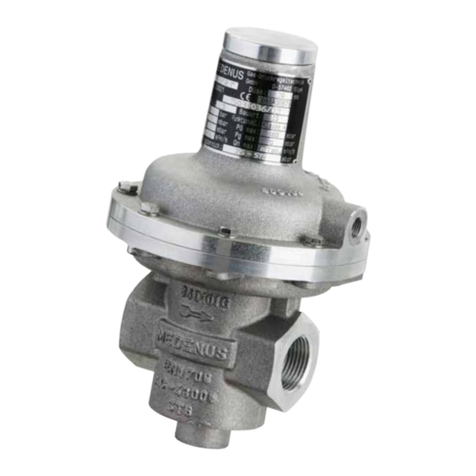
MEDENUS SL 10 Manual

© 11.2016
Safety relief valve
SL 10
Operating and Maintenance Instructions

Subject to technical modifications! Reprint prohibited!

© 11.2016© 11.2016
Table of Contents
1 General Information 4
1.1 Warranty and Liability 4
1.2 Symbols, Notes 5
1.3 Terms, Abbreviations 5
2 Safety Instructions 6
2.1 Hazards of Handling the Device 6
2.2 Personnel Requirements 6
2.3 Country-Specific Requirements 6
2.4 Handover of the Operating and Maintenance Instructions 6
2.5 Safety in Operation 7
2.6 What To Do in Case of Danger 7
3 Responsibility of the Operator 7
4 Transport, Storage and Packaging 8
4.1 Transport 8
4.2 Storage 8
4.3 Packaging 8
5 Mounting and Commissioning 9
5.1 Safety Instructions and Preparation 9
5.2 Mounting 10
5.3 Leakage Test (Test for External Leakage) 11
5.4 Initial Commissioning / Recommissioning 12
5.5 Decommissioning 13
6 Maintenance 13
6.1 Maintenance Plan 13
6.2 Maintenance Procedure 14
6.3 Table of Screw Tightening Torques MA14
6.4 Lubricants Table 14
7 Troubleshooting 15
7.1 Safety Relief Valve 15
8 Replacement and Disposal 16
9 Spare Parts 16
9.1 Parts for Maintenance Work 16
O-Rings and Sealing Rings 16
Valve Plates / Diaphragms 16
9.2 Spare Parts Drawing SL10 17
10 Declaration of Conformity 18
11 Notes 19

4
© 11.2016
1 General Information
The personnel entrusted with installation, operation or maintenance of the safety relief valve must
have completely read and understood beforehand the following documents:
• Safety Relief Valve SL 10 Product Information
The product information contains technical data, dimensions and a description of the design and the mode of
operation.
• Safety Relief Valve SL 10 Operating and Maintenance Instructions
This document allows safe and efficient handling of the device and contains information on assembly,
commissioning, maintenance, troubleshooting, and repair according to regulations.
It is an integral part of the scope of delivery of the device, must be kept in close proximity of the device and
must be readily accessible to personnel at any time.
The basic requirement of safe operation is compliance with all safety instructions and guidelines specified in
these instructions. Accordingly, the information and instructions must be observed when working on the device
or on the gas line. In addition, the local occupational safety regulations and the general safety regulations for
the application range of the device shall apply.
The figures in these instructions are provided for basic understanding and may differ from the actual design.
The contents in these instructions are protected by copyright. They may be used as part of operating the
device. Any other use and / or reproduction is not permitted without prior authorization by the MEDENUS Gas-
Druckregeltechnik GmbH.
1.1 Warranty and Liability
Claims under warranty or liability for personal injury and material damage are generally void,
if one or several of the following conditions are not observed:
• Work on the device during the warranty period may only be performed in consultation with the manufacturer
• Designated use of the device in accordance with the established conditions of use
• Proper installation, commissioning, operation and maintenance of the device
• Operation of the device with properly installed and functioning safety devices only
• Operating and maintenance instructions of the device or of the system
• Observance of the maintenance instructions
• Properly performed repairs
• Supply lines without defects
• The use of original MEDENUS©spare parts and lubricants listed in these instructions or
• Force majeure
It is generally prohibited
• to perform constructive modifications on the device
• to keep using the device despite the detection of a defect

5© 11.2016
1.3 Terms, Abbreviations
Terms and abbreviations are explained below:
1.2 Symbols, Notes
The instructions contain safety instructions marked with symbols to indicate possible consequences in case of non-
observance:
DANGER
Note
NOTICE
This combination of symbol and signal word indicates a potentially hazardous
situation which may result in light injuries, damage to the device, the breakdown
of the system, and material or environmental damage if not avoided.
This combination of symbol and signal word indicates an imminent hazardous
situation, resulting in death or serious injuries if not avoided.
This signal word highlights useful tips, recommendations, and information for
efficient and trouble-free operation.
ATC Acceptance test certificate
DN Nominal width
GPR Gas pressure regulator
MOP Maximum operating pressure
in a system
SSV Safety shut-off valve
SRV Safety relief valve

6
© 11.2016
2 Safety Instructions
National accident prevention regulations and the system operator‘s safety regulations are not superseded by these
operating and maintenance instructions and must be taken into consideration with priority (in Germany, see, among
others, DVGW Code of Practice G 600, G 459/II, G 491 and G 495)
When performing work on the device, the current general and specific safety regulations must be observed.
The application limits of the device with respect to the medium, operating pressure and operating temperature can be
found on the type plate affixed to the device or on the acceptance test certificate.
Using the device under different operating conditions must be agreed upon in consultation with
MEDENUS Gas-Druckregeltechnik GmbH.
The mechanical components of the device do not have any potential ignition sources of their own nor any hot surfaces and
are thus not within the scope of 2014/34/EU (ATEX). The electronic accessories used comply with the ATEX requirements.
2.1 Hazards of Handling the Device
MEDENUS©devices conform with current standards and directives, the recognized technical rules and the recognized
safety rules.
However, improper use can result in hazards to the user or to third parties. This can also result in damage to the device
or to the system.
This is why the device may only be used:
• in accordance with its designated use
• in perfect condition
• while observing the notes given in these operating and maintenance instructions, and inspection and
maintenance regulations, which apply to the functioning and safety of the overall system.
Malfunctions or faults must be eliminated immediately.
2.2 Personnel Requirements
The device may only be mounted by qualified personnel.
Only authorised personnel in possession of the required qualification is allowed to perform settings or repairs on the
device.
2.3 Country-Specific Requirements
The rules and regulations applicable at the place of use with respect to:
• gas lines, installation of the gas system
• gas supply
• work on the gas system
• accident prevention must be observed and complied with.
2.4 Handover of the Operating and Maintenance Instructions
The supplier of the system shall hand over these operating and maintenance instructions to the operator of the system
no later than during commissioning and training of the operating personnel with the reminder to carefully store these
instructions.

7© 11.2016
2.5 Safety in Operation
The device may only be used when all protective devices on the device or in the system are fully
functional.
At least once a year, the device must be inspected for externally visible damage and for proper functioning
by a representative of the manufacturer or by a qualified person.
A more frequent inspection may become necessary, depending on the system conditions.
2.6 What To Do in Case of Danger
Information on what is to be done in case of danger and in case of accidents can be found in the respective operator's or
specialist company's work instructions.
3 Responsibility of the Operator
Operator An operator is a person who operates the device himself for commercial or economic purposes or hands
it over to a third party for use / application and is legally responsible for the safety of the user, personnel
or third parties.
The device is used in the industrial sector. Accordingly, the operator of the device is subject to the legal
obligations concerning occupational safety. In addition to the safety instructions contained in these
instructions, the established maintenance intervals must be observed, taking into account the respective
national standard (alarm and hazard prevention plan).
In particular, the following applies:
• The operator is obliged to perform work on MEDENUS©devices during the warranty period only
after consultation with the manufacturer. Otherwise the claims under warranty will become
void.
• The operator must obtain information on the current occupational safety regulations and
determine additional hazards resulting from the special work conditions at the place of use of
the device in a risk assessment. The operator must implement them in the form of operating
manuals for operating the device.
• During the entire time of use of the device, the operator must check whether the operating
manuals drawn up by him conform to the current state of the regulations and, if necessary,
adapt them.
• The operator must clearly regulate and define the responsibilities for installation, operation,
troubleshooting, maintenance, and cleaning.
• The operator must ensure that all persons handling the device have read and understood these
instructions. In addition to that, he must train the personnel at regular intervals and inform it
about the dangers.
• The operator must make available to the personnel the required protective equipment and
oblige them to wear the required protective equipment.
• Moreover, the operator is responsible for the device always being in technically perfect condition.
Therefore, the following applies:
• The operator must make sure that the maintenance intervals described in these instructions
are observed.
• The operator must have all safety devices checked regularly for functioning and completeness.
Operator's
obligations

8
© 11.2016
4 Transport, Storage and Packaging
4.1 Transport
The device must be handled carefully and secured against impact and shock.
In case of transport damage, we will require the following information from the type plate affixed to
the device:
• Type of device
• Device model
• Year of construction / fabrication number
Note
4.2 Storage
Equipment and spare parts must be stored under the following conditions:
• Do not store outdoors.
• Store in a dry and dust-free location.
• Store on a flat surface.
• Do not expose to aggressive media.
• Do not expose to ozone or ionizing radiation.
• Do not store adjacent to direct heat sources.
• Avoid mechanical vibrations.
• Storage temperature: 0 to 25°C.
• Relative humidity: < 55 %.
Spare parts:
• Components susceptible to corrosion must be provided with a suitable preservative.
• Do not store O-rings and seals for more than 7 years even if stored properly.
• Spare parts must be stored in their original packaging until use.
Storage period for devices:
• Storage of the device for up to one year:
Store the safety relief valve in its original packaging and original condition at the time of supply. All protective
caps of the device must remain mounted.
• Storage of the device for more than 1 year (e.g. as a spare device):
Store the device in its original packaging and original condition at the time of supply and check it for damage
once a year. Check the housing surface for dirt, damage and corrosion. If necessary, clean all external parts.
After 7 years, all O-rings and seals must be replaced.
4.3 Packaging
• The individual packaged items have been packaged in view of the transport conditions to be expected.
• The symbols on the packaging must be observed during transport and storage.
• Only environmentally-friendly materials have been used for packaging.
• The packaging is designed for protecting the individual components from transport damage, corrosion and
other damage until mounting. This is why the packaging must not be destroyed and only be removed just prior
to mounting.

9© 11.2016
5 Mounting and Commissioning
5.1 Safety Instructions and Preparation
Prior to starting work on pressurised components:
• Close all connections to the gas line.
• Depressurise all pressurised components. Also discharge residual energies.
• Defective components that are subject to pressure in operation must be replaced
immediately by a suitable qualified person.
Prior to starting work, ensure sufficient clearance for mounting.
Before installing the device, check whether the performance data (type plate) and the scope of
delivery coincide with the order or the system data, i.e., make sure that the provided devices are
suitable for their intended purpose. In particular, the inlet pressure of the system must be lower
than the maximum allowable pressure of the device or the system must be declared to be differential
pressure-resistant.
A direct contact of gas valves and fittings, i.e., the control system, with hardening masonry, concrete
walls or floors is not allowed. Provide suitable supports, working materials, and protective equipment.
Take into account the minimum clearances for maintenance as stated in the product information.
Before installing the device in the pipeline, check whether a shut-off device that interrupts the gas
flow supply to the device has been mounted upstream of the device to be installed.
Prior to commissioning, make sure that all installation work has been carried out and completed
in accordance with the data and information given in these instructions and that no unauthorised
persons stay in the danger zone.
DANGER
Note
Note
DANGER

10
© 11.2016
5.01 5.02
5.04
5.10
5.09
5.13
5.12
5.11
5.2 Mounting
• Install the safety relief valve (item 5.09) without twisting the pipeline.
Make sure to observe the direction of flow, i.e., the arrow on
the housing must point in the direction of flow.
• All breather lines (item 5.04) must be vented to the outside atmosphere.
• Breather lines (item 5.04) may not be required
if breather valves are being used.
Note
Note

11 © 11.2016
U
S
G
a
s
-
D
r
u
c
k
r
e
g
e
l
g
e
r
ä
t
D
E
N
U
S
G
a
s
-
D
r
u
c
k
r
e
g
e
l
g
e
r
ä
t
5.10
5.09
5.10
5.09
For Germany:
According to DVGW Code of Practice G 491, the fully assembled system must be subjected to a leakage test with air or
an inert gas at the installation site, using 1.1 times the maximum operating pressure of the system (MOP).
An exception is the room between the actuator installed in the gas pressure regulator and the first shut-off valve on the
outlet side. This room must be checked using the a test pressure corresponding to the maximum permissible pressure
in the system in case of a malfunction (1.1 MOPd). In this test, all detachable connections must be checked using a
foaming agent.
For other countries:
The relevant national and international standards shall apply.
Procedure
• Close the ball valves upstream of the valves and fittings (item
5.01).
• Close the downstream shut-off devices (item 5.13) (ball valves,
solenoid or pneumatic valve).
• Depressurise the system (item 5.11).
• Connect the testing device to measuring points upstream and
downstream of the gas pressure regulator (items 5.02 / 5.12).
• Test the tightness of the safety relief valve (item 5.09) until the
response pressure is reached and then close the line upstream of
5.3 Leakage Test (Test for External Leakage)
The devices are subjected to a strength and leakage test ex works at MEDENUS Gas-Druckregeltechnik GmbH.
The leakage test in the fully assembled system must be performed prior to commissioning and following maintenance
work.
For the external leakage test in the fully assembled system, the following applies:
the SRV (item 5.10).
• Always increase the test pressure slowly and steadily.
While doing so, you must ensure:
Pressure in outlet chamber (item 5.12) ≤Pressure in inlet chamber (item 5.02)
Pressure build-up always from the inlet side (inlet chamber)
Pressure reduction always from the outlet side (outlet chamber)
• After leakage test:
Open the ball valve in the SRV line (item 5.10) again.
Note
NOTICE

12
© 11.2016
5.21
M
E
D
E
N
U
S
G
a
s
-
D
r
u
c
k
r
e
g
e
l
g
e
r
t
M
E
D
E
N
U
S
G
a
s
-
D
r
u
c
k
r
e
g
e
l
g
e
r
t
5.22
5.25
5.4 Initial Commissioning / Recommissioning
Initial commissioning of the system components shall be carried out by the operator. For commissioning, please refer to
the documents listed under item 1 "General Information" and the system operator's work instruction.
The devices delivered by MEDENUS Gas-Druckregeltechnik GmbH are factory-set to the operating data specified by the
customer. This data is listed on the Acceptance Test Certificate (ATC)* and the type plate.
• For a functional test of the SRV, increase the gas pressure with the controller
until the SRV reacts and read the set regulating pressure on the outlet
pressure gauge (item 5.12).
• If necessary, correct the response pressure.
This is done by turning the SRV setpoint setting screw (item 5.22) to the right
or left, in order to increase and decrease the setpoint, respectively, after
removal of the GPR sealing cap (item 5.21).
• Screw on the SRV sealing cap (item 5.21) again.
Changing the control range
Switching to the control range of a different setpoint spring can be done for the SRV
while the device is pressurised.
• Take off the sealing cap (item 5.21) and unscrew the setting screw (item 5.22),
• Pull out the spring (item 5.25) and replace the spring with one that fits.
• Screw in the setting screw (item 5.22) again.
• Set the desired setpoint and screw on the sealing cap (item 5.21) again.
*) Acceptance Test Certificate (ATC) available optionally

13 © 11.2016
6 Maintenance
6.1 Maintenance Plan
The maintenance regulations of the system manufacturer must be observed. The following sections describe the
maintenance work required for optimal and trouble-free operation of the device.
If increased wear is detected during regular inspections, the required
maintenance intervals must be shortened in accordance with the actual wear.
For any questions on maintenance work and intervals, please contact the manufacturer.
The intervals for monitoring and maintenance work are strongly dependent on the
operating situation and the condition of the gas. This is why no fixed intervals
can be given. For Germany, it is recommended to initially observe the maintenance periods according to
the data given in DVGW Code of Practice G 495. For each system, this must be followed by
determining the maintenance interval independently on a medium-term basis.
During maintenance work, the components must be cleaned and subjected to a thorough visual inspection. This is
also necessary if irregularities in the operating behaviour have been detected during operation
or during functional tests. The check must cover the elastomers in particular.
Damaged parts and O-rings dismounted during dismantling must be replaced with new ones.
It is recommended to stock the parts listed in chapter 9.1 on page 16 for maintenance work.
Interval Maintenance activities Personnel
When required
Replacing O-rings
Qualified person
Replacing diaphragms
Replacing the valve plate
Replacing sealing rings for the connections of the breather lines
5.5 Decommissioning
For decommissioning, please refer to the documents listed under item 1 "General Information"
and the system operator's work instruction.
Procedure
• Slowly close the outlet shut-off valve (item 5.13) or
• Slowly lower the outlet pressure via the setpoint setting screw until the reserve rail takes over the gas supply
or
• Slowly raise the setpoint of the reserve rail until the operating rail is disabled.
• Close the ball valves upstream of the valves and fittings (item 5.01).
• Depressurise the system (item 5.11).
• Close venting ball valve (item 5.11).

14
© 11.2016
51
50
6.2 Maintenance Procedure
The maintenance procedure is described in detail step-by-step in our video tutorial and our pictorial descriptions.
Instructions for our products can be found in the download area of our website. Should you have any problems, please
feel free to contact us directly.
If components have been removed, make sure they are mounted correctly, reinstall all fastening
elements and observe the screw tightening torques.
Prior to recommissioning, observe the following:
• Make sure that all maintenance work has been carried out and completed in accordance
with the data and information given in these instructions.
• Make sure there are no unauthorised persons in the danger zone.
• Make sure that all covers and safety devices have been installed and are working properly.
For recommissioning, please refer to the relevant manufacturer's documentation of the
gas pressure regulator installed in the system, the work instructions of the system operator, and the other
safety regulations of the system in which the safety relief valve has been installed.
To guarantee smooth operation, we recommend always keeping a maintenance set in reserve.
NOTICE
DANGER
Note
6.3 Table of Screw Tightening Torques MA
Item
No.
SL10 / Rp 1“
SL10 / Rp 1 1/2“
SL10 / Rp 2“
50 M6 / 8 Nm
51 M6 / 8 Nm
6.4 Lubricants Table
Components (apply a thin layer) Lubricants Article number
All O-rings Syntheso Proba 270 SYNTHESO-PROBA-270
All fastening and locking screws Anti Seize AS 450 AS-450

15 © 11.2016
7 Troubleshooting
7.1 Safety Relief Valve
Description of the error Possible cause Elimination
SRV vents during
operation
Actuator dirty or damaged Check valve plate (seal) and valve seat for damage
and dirt, replace valve plate, if necessary
Static sealing elements defective Replace O-rings
Valve plate has become disconnected
from the valve stem Tighten nut under the valve plate
Wrong SRV settings Check SRV settings
SRV set too low Check SRV settings
Sluggishness of the device due to dirt Subject device to maintenance
SSV frequently shuts
off
Stopcock upstream of SRV is closed Open stopcock
SSV set too low or SRV set too high Check SSV and SRV settings
Gas escapes through
breather line
Fastening of the main diaphragm has
come off
Main diaphragm is damaged or has
been mounted incorrectly
Check diaphragm for fastening, damage and correct
fit

16
© 11.2016
9.1 Parts for Maintenance Work
O-Rings and Sealing Rings
Item
no.
Name Quantity
pcs.
Exception SL10 / Rp 1“
SL10 / Rp 1 1/2“
SL10 / Rp 2“
4 O-ring 1 O-013
7 O-ring 1 O-007
11 O-ring 1 O-007
14 NBR-ring 2 N-001
20 O-ring 1 O-013
2 HD2 O-013
O-ring set
order number: OS-081
Example:
Safety relief valve: SL10 / Rp1“
Spare parts according to tables in 9.1
Valve plate SRV: VT-212
Diaphragm SRV: M-111
O-ring and sealing ring set: OS-081
Info: The allocation of individual parts is done according to the item no. in the tables in 9.1, conforming to the spare
parts drawings in 9.2.
Valve Plates / Diaphragms
Item
no.
Name Number SL10 / Rp 1“
SL10 / Rp 1 1/2“
SL10 / Rp 2“
6 Valve plate 1 VT-213
16 Diaphragm 1M-111
8 Replacement and Disposal
After the device has reached the end of its useful life, it must be dismounted and disposed of in an
environmentally compatible manner.
During dismounting, components that may present a risk of injury by contamination,
depending on the medium are removed. Depending on the processed medium, the
components must be properly decontaminated. Components capable
of diffusion (diaphragm, O-ring, etc.) may have to be taken to a special disposal unit,
depending on the material used. If no return or disposal agreement
has been reached, dismantled components should be recycled:
• Metals should be scrapped
• The remaining components should be disposed of after sorting according to material.
For technical information, please contact our customer service:
MEDENUS Gas-Druckregeltechnik GmbH
Saßmicker Hammer 40
D-57462 Olpe
Phone +49 (0) 2761 / 82788-0
Fax +49 (0) 2761 / 82788-9
In addition, we are always interested in information and experience resulting from the application and
which can be valuable for improving our products.
E-Mail [email protected]
Internet www.medenus.de
NOTICE
9 Spare Parts

17 © 11.2016
20
16
11
14
6
7
4
20
SL10 shown with
high-pressure spindle HD2
9.2 Spare Parts Drawing SL10

18
© 11.2016
Konformitätserklärung
(Zusammenfassung)
Hersteller: Medenus Gas-Druckregeltechnik GmbH
Anschrift: Saßmicker Hammer 40
D-57462 Olpe-Saßmicke
bescheinigt hiermit, dass das Produkt:
SL 10 Sicherheits-Abblaseventil
einer EG-Baumusterprüfung unterzogen wurde und den
grundsätzlichen Anforderungen der Richtlinien GAD 2009/142/EG
EG-Gasgeräterichtlinie in der gültigen Fassung entspricht.
Für Geräte, die zusätzlich mit dem CE-Kennzeichen gekennzeichnet
sind, liegt eine EG-Baumusterprüfbescheinigung vor nach:
EU/97/23/EG A III B EG-Druckgeräterichtlinie
Prüfbericht: CE-0085 / AZ 12/009/4305/116 (SL10)
Grundlage der EG-Baumusterprüfung sind die harmonisierten
europäischen Normen und/oder nationalen Normen:
DIN 33821 (01.03.2009)
Kennzeichnung (PIN) nach Gasgeräterichtlinie
CE-0085AQ0879 Modell SL 10
Kennzeichnung nach Druckgeräterichtline
Die Überwachung des Qualitätssicherungssystems (Modul D) erfolgt
durch den DVGW.
Olpe-Saßmicke,
30.09.2016
Martin Clemens
Geschäftsführer
Declaration of Conformity
(Summary)
Manufacturer: Medenus Gas-Druckregeltechnik GmbH
Address: Saßmicker Hammer 40
D-57462 Olpe-Saßmicke
herewith declares that the product:
SL 10 Safety Relief Valve
has been subjected to an EC type examination and conforms to
the basic requirements of the directives GAD 2009/142/EC
EC Gas Appliances Directive in the respective current version.
For devices that additionally carry the CE mark,
an EC-type-examination certificate has been issued according to:
EU/97/23/EC A III B EC Pressure Equipment Directive
Test report: CE-0085 / AZ 12/009/4305/116 (SL10)
The EC type-examination is based on the harmonised
European Standards and/or national standards:
DIN 33821 (2009-03-01)
Marking (PIN) according to Gas Appliances Directive
CE-0085AQ0879 model SL 10
Marking according to Pressure Equipment Directive
The quality assurance system (module D) is monitored
by the DVGW.
Olpe-Saßmicke,
2016-09-30
Martin Clemens
Managing Director

19 © 11.2016
..............................................................................
..............................................................................
..............................................................................
..............................................................................
..............................................................................
..............................................................................
..............................................................................
..............................................................................
..............................................................................
..............................................................................
..............................................................................
..............................................................................
..............................................................................
..............................................................................
..............................................................................
..............................................................................
..............................................................................
..............................................................................
..............................................................................
..............................................................................
..............................................................................
..............................................................................
..............................................................................
..............................................................................
..............................................................................
..............................................................................
11 Notes
German:
http://medenus.de/files/upload/
downloads/SL10/BWA_SL10_de.pdf
In the download area of our homepage, this document is available in different languages. You can use the following
QR codes and links to go directly to this document in your language.

MEDENUS Gas-Druckregeltechnik GmbH
Fon +49 (0)2761 82788-0
Fax +49 (0)2761 82788-9
Saßmicker Hammer 40 / D-57462 Olpe
www.medenus.de
Other manuals for SL 10
1
Table of contents
Other MEDENUS Control Unit manuals
Popular Control Unit manuals by other brands

MADDALENA
MADDALENA Arrow WAN 2 Instructions for installation, use and maintenance

Resol
Resol HKM3 manual
Macnaught
Macnaught HG 55 Series instruction manual
Metso
Metso D Series Installation, maintenance and operation instructions

Dewetron
Dewetron XR-RTD8 Technical reference manual
Harvia
Harvia C150 manual

Samson
Samson 3321 Mounting and operating instructions
resideo
resideo Braukmann D05FT installation instructions

Teletek electronics
Teletek electronics TTE Combo manual
SOMAS
SOMAS SKV Service and operating instruction
Vexve
Vexve Hydrox HCU Remote Installation, operation and maintenance instructions
Weir
Weir SPM Operating and maintenance instructions

