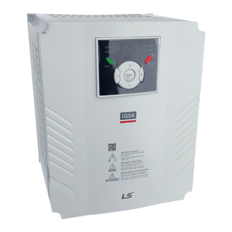
LSIS S100 Series User manual

Safety Precautions
I
Thank you for purchasing S100 Series Extension I/O.
SAFETY PRECAUTIONS
Always follow safety instructions to prevent accidents and potential hazards
from occurring.
Safety precautions are classified into “WARNING” and “CAUTION” and their
meanings are as follows:
WARNING
Improper operation may result in serious personal injury or
death.
CAUTION
Improper operation may result in slight to medium personal
injury or property damage
The indicated illustrations on the product and in the manual have the
following meanings.
Danger may be present. Read the message and follow the instructions
carefully.
Particular attention should be paid because danger of an electric shock
may be present.
Keep operating instructions handy for quick reference.
Read the operating instructions carefully to fully understand the functions of
the S100 series and to use it properly.
CAUTION
Be cautious, when handling the CMOS components of the
communication module.
Static may lead to malfunctioning of the product.
Turn off the inverter power, when changing the communication cable.
Otherwise, you may damage the module or a communication error may occur.
Make sure to insert the Option board connector to the inverter precisely.
Otherwise, you may damage the module or a communication error may occur.
Check the parameter unit before setting up the parameter.
Otherwise, a communication error may occur.

Table of Contents
ii
Table of Contents
Chapter 1. Basic Information & Precautions
.............................................................................. 1
1.1 Characteristics .......................................................................................................................................................................... 1
1.2 Components ............................................................................................................................................................................. 1
Chapter 2. Specifications
................................................................................................. 2
2.1 External Dimension ................................................................................................................................................................. 2
2.2 Input and Output Specification ........................................................................................................................................... 3
Chapter 3. Installation
..................................................................................................... 4
3.1 Installation of S1 Extension I/O ....................................................................................................................................... 4
3.2 Control Terminal Wiring ......................................................................................................................................................... 6
3.3 Signal (Control) Cable Specifications ................................................................................................................................. 8
Chapter 4. Basic Features
............................................................................................... 11
4.1 Basic function ......................................................................................................................................................................... 11
4.2 Setting Frequency Reference ............................................................................................................................................. 11
4.2.1 V3 Terminal as the Source................................................................................................................................ 11
4.2.2 Setting a Frequency Reference with Input Voltage (Terminal I4) ........................................................ 17
4.3 Analog Output ....................................................................................................................................................................... 18
Voltage and Current Analog Output ................................................................................................................................. 18
4.4 Digital Output ......................................................................................................................................................................... 20
4.4.1 Multi-function Output Terminal and Relay Settings ................................................................................ 20
4.4.2
Fault Trip Output using Multi-Function Output Terminal and Relay
................................................................ 23
4.4.3
Multi-function Output Terminal Delay Time Settings
........................................................................................ 24
4.5 Setting Multi-step Frequency ............................................................................................................................................ 25
4.6 Multi-step Acc/Dec Time Configuration.......................................................................................................................... 27
4.7 Stopping the Acc/Dec Operation ..................................................................................................................................... 28
4.8 Multi-function Input Terminal Control ............................................................................................................................ 29
A terminal setting (On)
................................................................................................... 29
Chapter 5. Table of Functions
.......................................................................................... 30
5.1 Operation Group.................................................................................................................................................................... 30
5.2 Drive group (PAR→dr).......................................................................................................................................................... 31
5.3 Basic Function group (PAR→bA) ....................................................................................................................................... 35
5.4 Expanded Function group (PAR→Ad) ............................................................................................................................. 38
5.5 Control Function group (PAR→Cn) .................................................................................................................................. 43
5.6 Input Terminal Block Function group (PAR→In) ........................................................................................................... 47
5.7 Output Terminal Block Function group (PAR→OU) ..................................................................................................... 51
5.8 Communication Function group (PAR→CM) ................................................................................................................ 55
5.9 Application Function group (PAR→AP) .......................................................................................................................... 59
5.1 Extension I/O Function Group(PAR→AO) ............................................................................................................. 61
5.11 Protection Function group (PAR→Pr) .................................................................................................................... 63
5.12 2nd Motor Function group (PAR→M2) ................................................................................................................. 68
5.13 User Sequence group (US) ........................................................................................................................................ 70
5.14 User Sequence Function group(UF) ....................................................................................................................... 72
5.15 Groups for LCD Keypad Only .................................................................................................................................... 88
5.15.1
Trip Mode (TRP Last-x)
.......................................................................................................................................... 88
5.15.2
Config Mode (CNF)
................................................................................................................................................ 89
Chapter 1. Basic Information & Precautions
1
Chapter 1. Basic Information & Precautions
Before installation of S1 Extension I/O, this chapter explains basic information and precautions
(The Extension I/O is supported by the product S/W V2.1 or higher.)
1.1 Characteristics
Additional terminals
Digital Input : 3ea
Digital Output : 2ea(1FormC)
Analog Input : 2ea
Analog Output : 1ea
1.2 Components
S1 Extension I/O consists of following items.
S1 Extension I/O : 1ea
User manual : 1ea
Brass supporter(M3xL17.3) : 1ea
Brass supporter(M3xL23) : 1ea
Screw(M3xL8) : 2ea
Other parts
If you find damaged or missing parts, please contact LSIS office(refer to the end of this manual).

Chapter 2. Specifications
2
Chapter 2. Specifications
2.1 External Dimension

Chapter 2. Specifications
3
2.2 Input and Output Specification
Function abel
Name Description
IN
PUT
Multi-
function
terminal
configuration
P8 ~
P1
Multi-function
Input 8~1 Configurable for multi-function input terminals.
CM Common
Sequence Common terminal for analog terminal inputs and outputs.
Analog input
configuration
V3
Voltage input
for frequency
reference input
Used to setup or modify a frequency reference via analog
voltage input terminal.
• Unipolar: –1 V (12V Max.)
• Bipolar: -1 –1 V (±12V Max.)
I4
Voltage/current
input for
frequency
reference input
Used to setup or modify a
frequency reference via analog
voltage or current input terminals.
Switch between voltage (V4) and current (I4) modes using a
control board switch (SW2).
V4 Mode:
• Unipolar: –1 V (12V Max.)
I4 Mode
• Input current: 4–2 mA
• Maximum Input current: 24mA
• Input resistance: 249Ω
OUT
PUT
Analog
Output AO3 Voltage/Curren
t Output
devices: output frequency, output current, output voltage,
or a DC voltage.
Operate switch (SW3) to select the signal output type
(voltage or current) at the AO terminal.
Output Signal Specifications:
• Output voltage: –1 V
• Maximum output voltage/current: 12V/1 mA
• Output current: –2 mA
• Maximum output current: 24mA
• Factory default output: Frequency
Digital
Output
CM Common
Sequence Common terminal for analog terminal inputs and outputs.
A3,
C3,
B4
Fault signal
output
Sends out alarm signals when the inverter’s safety features
are activated (AC 25 V <1A, DC 3 V < 1A).
Fault condition: A3 and C3 contacts are connected (B3 and
C3 open connection)
Normal operation: B3 and C3 contacts are connected (A3
and C3 open connection)
A4,
C4,
B4
Fault signal
output
Sends out alarm signals when the inverter’s safety features
are activated (AC 25 V <1A, DC 3 V < 1A).
Fault condition: A4 and C3 contacts are connected (B4 and
C4 open connection)
Normal operation: B4 and C4 contacts are connected (A4
and C4 open connection)

Chapter 3. Installation
4
(1)
(2)
Chapter 3. Installation
3.1 Installation of S100 Extension I/O
Warning) Connect a communication network after the power supply of the S1 inverter must be off.
If the power supply is plugged when Extension I/O is removed, the S1 inverter will be damaged entirely.
Take off Extension I/O from the product after the power supply is totally discharged.
In case of
LSLV 4S1 -2EXNNS, LSLV 8S1 -2EXNNS, LSLV 4S1 -4EXFNS, LSLV 8S1 -4EXFNS, it is
impossible to do wiring of main source after assembly of Extension I/O. Please assemble Extension I/O after
wiring of main source. If you need to using built-in I/O terminals, please do wiring of the terminals before
assembly of extension I/O
■ Take off the power supply cover
and the I/O cover((1), (2)) from
a dedicated S1 inverter
for communication.
■ Take off the keypad (3).
■ Loosen a screw from
the I/O board and
fasten the prepared
brass bar (M3xL23) to (4),
and (M3xL17.3) to (5).
(3)
(4)
(5)

Chapter 3. Installation
5
■ Mount the Extension I/O(6) and fasten
the removed screw(7)
and the included screw(8).
■ Install the keypad (9) at first and
the Extension I/O cover(1 ) in order.
■ Install the power supply cover(11) again
And the installation is completed.
(10)
(9)
(11)
(6)
(7)
(8)

Chapter 3. Installation
6
3.2 Control Terminal Wiring
■ NPN(Sink)/PNP(Source) Mode Selection
The S1 Extension I/O supports both PNP (Source) and NPN (Sink) modes for sequence inputs at the terminal.
Select an appropriate mode to suit requirements using the PNP/NPN selection switch (SW1) on the control
board. Refer to the following information for detailed applications.
II VI
IO VO

Chapter 3. Installation
7
▪NPN Mode (Sink)
Select NPN using the PNP/NPN selection switch (SW1). Note that the factory default setting is NPN mode. CM
is is the common ground terminal for all analog inputs at the terminal, and P12 is 12V internal source.

Chapter 3. Installation
8
▪PNP Mode (Source)
Select PNP using the PNP/NPN selection switch (SW1). Note that the factory default setting is NPN mode. CM is
is the common ground terminal for all analog inputs at the terminal, and P12 is 12V internal source. If you are
using an external Voltage source, build a circuit that connects the external source (-) and the CM terminal In case
of PNP, you should apply more than 3V source for on-state and less than 2V for off-state.
3.3 Signal (Control) Cable Specifications
Terminals
Signal Cable
Without Crimp Terminal Connectors
(Bare Wire)
With Crimp Terminal Connectors
(Bootlace Ferrule))
mm2 AWG mm2 AWG
P8~P1 /CM/V3/I4 /AO3
.75
18
.5
2
A3/B3/C3
A4/B4/C4 1. 17 1.5 15

Chapter 3. Installation
9
▪
Preinsulated Crimp Terminal Connectors (Bootlace Ferrule)
.
Use preinsulated crimp terminal connectors to increase reliability of the control terminal wiring. Refer to the
specifications below to determine the crimp terminals to fit various cable sizes.
P/N
Cable Spec
Dimensions (inches/mm)
Manufacturer
AWG
mm2
*
P
d1
D
CE 25 6
26 .25
1 .4
.4
/
6.
. 4 / 1.1 .1 / 2.5 JEONO
(Jeono Electric,
http://www.jeono.com/)
CE 25 8
12.4
.5
/
8.
CE 5 6
22
.5
12.
.45
/
6.
. 5
/
1.3
.125
/
3.2
CE 75 6
2
.75
12.
.45
/
6.
. 6
/
1.5
.13
/
3.4
* If the length (L) of the crimp terminals exceeds .5” (12.7mm) after wiring, the control terminal cover may not
close fully.
To connect cables to the control terminals without using crimp terminals, refer to the following illustration
detailing the correct length of exposed conductor at the end of the control cable.
0.2”

Chapter 3. Installation
10
Note
While making wiring connections at the control terminals, ensure that the total cable length does
not exceed 165ft (5 m).
Ensure that the length of any safety related wiring does not exceed 1 ft (3 m).
Ensure that the cable length between an LCD keypad and the inverter does not exceed 1 ft
(3. 4m). Cable connections longer than 1 ft (3. 4m) may cause signal errors.
Use ferrite material to protect signal cables from electro-magnetic interference.
Take care when supporting cables using cable ties, to apply the cable ties no closer than 6 inches
from the inverter. This provides sufficient access to fully close the front cover.
When making control terminal cable connections, use a small flat-tip screw driver ( .1in wide
(2.5mm) and . 15in thick ( .4mm) at the tip).
0.1” or less
0.015” or less

Chapter 4. Basic Features
11
Chapter 4. Basic Features
4.1 Basic function
Basic Fundtion Example
Frequency reference source
configuration for the terminal
block (input voltage)
Configures the inverter to allow input voltages at the
terminal block (V3, V4) and to setup or modify a frequency
reference.
Frequency reference source
configuration for the terminal
block (input current)
Configures the inverter to allow input currents at the
terminal block (I4) and to setup or modify a frequency
reference.
Multi
-
step speed (frequency)
configuration
Configures multi
-
step frequency operations by receiving
an input at the terminals defined for each step frequency.
Multi
-
stage Acc/Dec time
configuration using the multi-
function terminal
Configures multi
-
stage acceleration and deceleration
times for a motor based on defined parameters for the
multi-function terminals.
Command source
configuration
for terminal block inputs
Configures the inverter to accept inputs at the FX/RX
terminals.
Multi
-
function input terminal
control configuration
Enables the user to improve the responsiveness of the
multi-function input terminals.
4.2 Setting Frequency Reference
Group Code Name CD Display
Parameter
Setting Setting Range Unit
Operation
Frq Frequency
reference source Ref Freq Src
KeyPad
-
1
–16 -
1
KeyPad
-
2
2
V1
4
V2
5
I2
6
Int 485
8
Field Bus
12
Pulse
13
V3
15
V4
16
I4
4.2.1 V3 Terminal as the Source
You can set and modify a frequency reference by setting voltage inputs when using the V3 terminal. Use voltage
inputs ranging from to 1 V (unipolar) for forward only operation. Use voltage inputs ranging from -1 to +1 V
(bipolar) for both directions, where negative voltage inputs are used reverse operations.

Chapter 4. Basic Features
12
Setting a Frequency Reference for 0–10V Input
Set the Frq (Frequency reference source) code in the Operation group to 13 (V3), and then set code 02
(V3 Polarity) to 0 (unipolar) in the AO group . Use a voltage output from an external source or use the
voltage output from the VR terminal(Standard I/O) to provide inputs to V3. Refer to the diagrams below
for the wiring required for each application.
Group
Code
Name
CD Display
Parameter Setting
Setting Range
Unit
Operation
Frq
Frequency reference
source Freq Ref Src 13
V3 –16 -
In 1
Frequency at maximum
analog input
Freq at 1 % Maximum frequency
.
–
Max. Frequency
Hz
Ao
1
V3 input monitor
V
3
Monitor [V]
.
.
–
12.
V
2
V3 polarity options
V3 Polarity Unipolar –1 -
3
V3 input filter time
constant V3 Filter 1
0–10000
ms
4
V3 minimum input
voltage
V3 volt x1 .
0.00–10.00
V
5
V3 output at minimum
voltage (%)
V3 Perc y1 .
0.00–100.00
%
6
V3 maximum input
voltage
V3 Volt x2 1 .
0 .00– 12.00
V
7
V3 output at maximum
voltage (%)
V3 Perc y2 1 . –1 %
8
Rotation direction
options
V3 Inverting No –1 -
9
V3 Quantizing level
V3 Quantizing . 4
. *,
. 4
–
1 . %
* Quantizing is disabled if ‘ ’ is selected.
V3
CM
[External source application]

Chapter 4. Basic Features
13
0–10V Input Voltage Setting Details
Code
Description
In. 1 Freq at 1 %
Configures the
frequency reference
at the maximum input voltage when a
potentiometer is connected to the control terminal block. A frequency set with
code In. 1 becomes the maximum frequency only if the value set in code Ao. 7
(or Ao.13) is 1 (%).
• Set code In. 1 to 4 . and use default values for codes Ao. 1–Ao. 9. Motor
will run at 4 . Hz when a 1 V input is provided at V3
• Set code Ao. 7 to 5 . and use default values for codes In. 1, Ao. 1–Ao. 9.
Motor will run at 3 . Hz (5 % of the default maximum frequency–6 Hz)
when a 1 V input is provided at V3.
Ao
.
1
V
3
Monitor[V]
Configures the inverter to monitor the input voltage at V
3
.
Ao. 3 V3 Filter
V
3
Filter may be used when there are large variations between
reference
frequencies. Variations can be mitigated by increasing the time constant, but this
will require an increased response time.
The value t (time) indicates the time required for the frequency to reach 63% of
the reference, when external input voltages are provided in multiple steps.
[V3 Filter ]
Ao. 4 V3 Volt x1–
Ao. 7 V3 Perc y2
These parameters are used to configure the gradient level and offset values of the
Output Frequency, based on the Input Voltage.
[Volt x1–Ao. 7 V3 Perc y2]
100%
63%
V3 Filter(t)
V3 input from
external source
Frequency
V3
Ao.06
Ao.04
Ao.05
Ao.07
Frequency reference
input

Chapter 4. Basic Features
14
Code
Description
Ao. 8 V3 Inverting
Inverts the direction of rotation. Set this code to 1 (Yes)
if you need the motor to
run in the opposite direction from the current rotation.
Ao. 9.V3
Quantizing
Quantizing may be used when the noise level is high in the analog input (V
3
terminal) signal.
Quantizing is useful when you are operating a noise-sensitive system, because it
suppresses any signal noise. However, quantizing will diminish system sensitivity
(resultant power of the output frequency will decrease based on the analog
input).
You can also turn on the low-pass filter using code Ao. 3 to reduce the noise, but
increasing the value will reduce responsiveness and may cause pulsations
(ripples) in the output frequency.
Parameter values for quantizing refer to a percentage based on the maximum
input. Therefore, if the value is set to 1% of the analog maximum input (6 Hz), the
output frequency will increase or decrease by .6Hz per .1V difference.
When the analog input is increased, an increase to the input equal to 75% of the
set value will change the output frequency, and then the frequency will increase
according to the set value. Likewise, when the analog input decreases, a decrease
in the input equal to 75% of the set value will make an initial change to the
output frequency.
As a result, the output frequency will be different at acceleration and
deceleration, mitigating the effect of analog input changes over the output
frequency.
[V3 Quantizing]

Chapter 4. Basic Features
15
Setting a Frequency Reference for -10–10V Input
Set the Frq (Frequency reference source) code in the Operation group to 13 (V3), and then set code 2
(V3 Polarity) to 1 (bipolar) in the APO group (Ao). Use the output voltage from an external source to
provide input to V3
[V3 terminal wiring]
[Bipolar input voltage and output frequency]
Group Code
Name CD Display
Parameter
Setting
Setting
Range Unit
Operation
Frq
Frequency reference
source
Freq Ref Src 13
V3 –16 -
In 1
Frequency at
maximum analog
input
Freq at 1 %
6 . – Max
Frequency Hz
Ao
1
V3 input monitor
V
3
Monitor
.
.
–
12. V
V
2
V3 polarity options
V
3
Polarity
1
Bipolar
–
1
-
1
V3 minimum input
voltage
V3- volt x1 . 1 . – . V V
11
V3 output at minimum
voltage (%)
V3- Perc y1 . -1 . – . %
%
12
V3maximum input
voltage
V3- Volt x2 -1 . -12. – . V V
13
V3 output at maximum
voltage (%)
V3- Perc y2 -1 . -1 . – . %
%
V3
CM

Chapter 4. Basic Features
16
Rotational Directions for Different Voltage Inputs
Command /
Voltage Input
Input
voltage
0–10V -10–0V
FWD
Forward
Reverse
REV
Reverse
Forward
-10–10V Voltage Input Setting Details
Code
Description
Ao.1 V3- volt x1–
Ao.13 V1- Perc y2
Sets the gradient level and off
-
set value of the output frequency in relation to the
input voltage. These codes are displayed only when Ao. 2 is set to 1 (bipolar).
As an example, if the minimum input voltage (at V3) is set to -2 (V) with 1 %
output ratio, and the maximum voltage is set to -8 (V) with 8 % output ratio
respectively, the output frequency will vary within the range of 6 - 48 Hz.
[Ao.1 V3-volt X1–Ao.13 V3 Perc y]
For details about the –+1 V analog inputs, refer to the code descriptions Ao.1
V3 volt x1–Ao.13 V1 Perc y2..
Setting a Reference Frequency using Input Current (I4)
You can set and modify a frequency reference using input current at the I4 terminal after selecting current input
at SW 2. Set the Frq (Frequency reference source) code in the Operation group to 16 (I4) and apply 4–2 mA
input current to I4.
Group
Code
Name
CD Display
Parameter Setting
Setting Range
Unit
Operation Frq
Frequency reference
source
Freq Ref Src 16 I4 –16 -
In 1
Frequency at maximum
analog input
Freq at 1 % 6 . – Maximum
Frequency Hz
Ao
22
I4 input monitor
I4 Monitor . . –24. mA
23
I4 input filter
time constant
I4 Filter 1 –1 ms
24
I4 minimum input current
I4 Curr x1 4. . –2 . mA
Ao.12 Ao.10
Ao.11
-8V -2V
6Hz
48Hz Ao.13
V3 input
Frequency reference

Chapter 4. Basic Features
17
Group
Code
Name
CD Display
Parameter Setting
Setting Range
Unit
25
I4 output at minimum
current (%)
I4 Perc y1 . –1 %
26
I4 maximum input current
I4 Curr x2 2 . . –24. mA
27
I4 output at maximum
current (%)
I4 Perc y2 1 . . –1 . %
28
I4 rotation direction options
I4 Inverting No –1 -
29
I4 Quantizing level
I
4
Quantizing
. 4
*,
. 4
–
1 .
%
* Quantizing is disabled if ‘ ’ is selected.
Input Current (I4) Setting Details
Code
Description
In. 1 Freq at 1 %
Configures the frequency reference for operation
at
the maximum current (when
Ao.27 is set to 1 %).
• If In. 1 is set to 4 . Hz, and default settings are used for Ao.24–27, 2 mA
input current (max) to I4 will produce a frequency reference of 4 . Hz.
• If Ao.27 is set to 5 . (%), and default settings are used for In. 1 (6 Hz) and
Ao.24–26, 2 mA input current (max) to I4 will produce a frequency reference
of 3 . Hz (5 % of 6 Hz).
Ao.22
I4
Monitor
Used to monitor input current at I4.
Ao.23 I4 Filter
Configures the time for the operation frequency to reach 63% of target
frequency based on the input current at I4.
In.24 I4 Curr x1–
In.27 I4 Perc y2
Configures the gradient level and off
-
set value of the output frequency.
[Gradient and off-set configuration based on output frequency]
4.2.2 Setting a Frequency Reference with Input Voltage (Terminal I4)
Set and modify a frequency reference using input voltage at I4 (V4) terminal by setting SW2 to V4. Set the Frq
(Frequency reference source) code in the Operation group to 15 (V4) and apply –12V input voltage to I4 (=V4,
Analog current/voltage input terminal). Codes Ao.14–21 will not be displayed when I4 is set to receive current
input (Frq code parameter is set to 16).
I4
Ao.26
Ao.24
Ao.25
Ao.27
Frequency Reference
input

Chapter 4. Basic Features
18
Group Code
Name CD Display
Parameter
Setting
Setting
Range Unit
Operation
Frq
Frequency
reference source Freq Ref Src 15 V4 –16 -
Ao
14
V
4
input display
V
4
Monitor
.
.
–
12.
V
15
V
4
input filter time
constant V4 Filter 1 –1 ms
16
Minimum V
4
input
voltage V4 Volt x1 . . –1 . V
17
Output% at
minimum V4
voltage
V4 Perc y1 . . –1 . %
18
Maximum V
4
input
voltage V4 Volt x2 1 . . –1 . V
19
O
utput% at
maximum V4
voltage
V4 Perc y2 1 . . –1 . %
2
Invert V
4
rotational
direction V4 Inverting No –1 -
21 V4 quantizing level V4 Quantizing . 4
.
*, . 4
–
1 . %
* Quantizing is disabled if ‘ ’ is selected.
4.3 Analog Output
An analog output terminal provides output of –1 V voltage, 4–2 mA current.
Voltage and Current Analog Output
An output size can be adjusted by selecting an output option at AO3(Analog Output3) terminal. Set the analog
voltage/current output terminal setting switch (SW3) to change the output type (voltage/current).
Grou
p Code
Name CD Display
Parameter
Setting Setting Range Unit
Ao
3
Analog output
3
AO
3
Mode
Frequency
–
15
-
31
Analog output
3
gain
AO
3
Gain
1 .
-
1 .
–
1 .
%
32
Analog output
3
bias
AO
3
Bias
.
-
1 .
–
1 .
%
33 Analog output3 filter AO3 Filter 5 –1 ms
34 Analog constant output3 AO3 Const %
. . –1 . %
35 Analog output3 monitor AO3 Monitor . . –1 . %
Other manuals for S100 Series
7
Table of contents
Other LSIS Control Unit manuals

LSIS
LSIS XGT Series User manual

LSIS
LSIS CENT-S100 User manual

LSIS
LSIS XGT Series User manual

LSIS
LSIS XGT Series User manual

LSIS
LSIS XGT Series User manual

LSIS
LSIS XGT Series User manual

LSIS
LSIS Starvert iG5A Series User manual

LSIS
LSIS XGB Series User manual

LSIS
LSIS S100 Series User manual

LSIS
LSIS XGT Series User manual
Popular Control Unit manuals by other brands

Novoferm
Novoferm HAD MS manual

Emerson
Emerson YARWAY 9100 ARC Series Installation, operation and maintenance instructions

Grundfos
Grundfos CU 361 manual

Allen-Bradley
Allen-Bradley ArmorBlock MaXum B Series installation instructions

Elektrogas
Elektrogas VMR01OTN manual

LOVATO ELECTRIC
LOVATO ELECTRIC EXP10 14 instruction manual