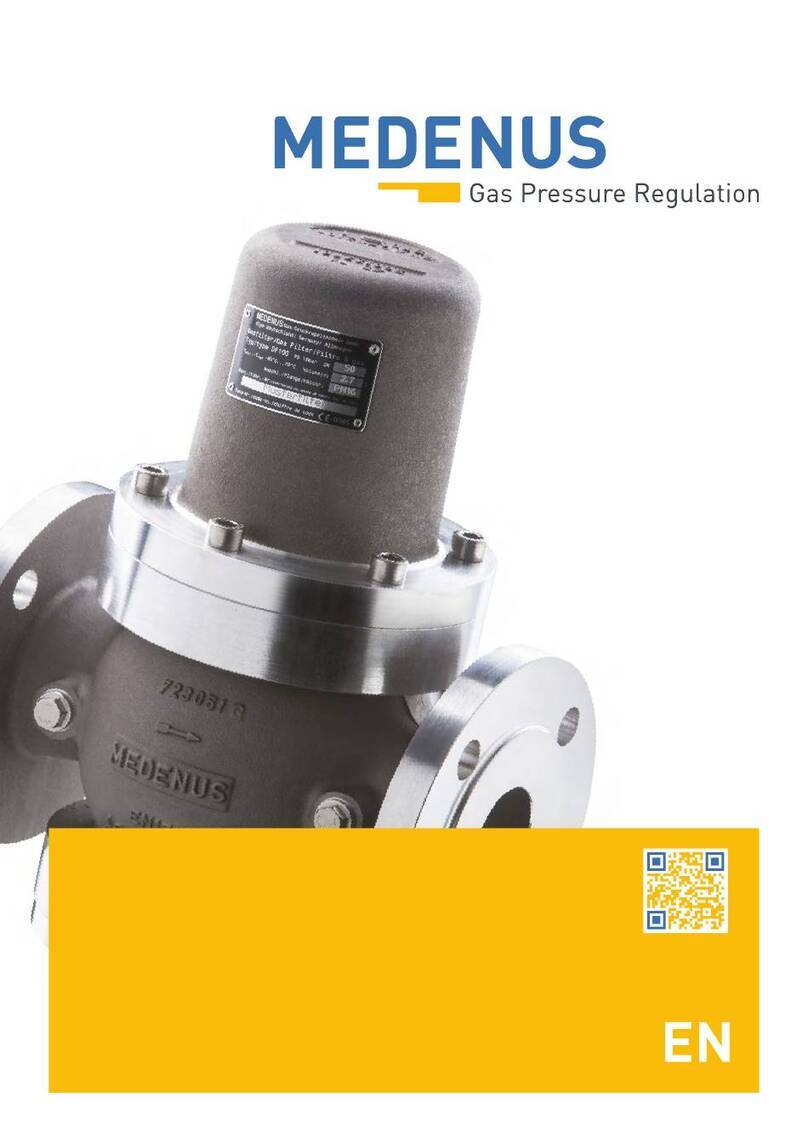
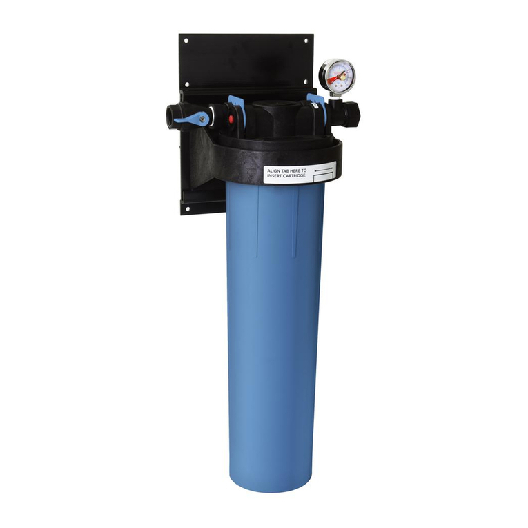
MEDENUS DF50 Manual

© 11.2023
Gas Filter
DF50
Operating and Maintenance Instructions

Subject to technical modifications! Reprint prohibited!

Design of the cellular gas filter DF50
Cover
Filter
cartridge Housing
Test points for
differential pressure
Housing

4
© 11.2023

5© 11.2023
Table of Contents
1 General Information 6
1.1 Warranty and Liability 6
1.2 Symbols, Notes 7
1.3 Terms, Abbreviations 7
2 Application, Characteristics 8
2.1 Application 8
2.2 Characteristics 8
2.3 Types of models (options) 8
3 Avoidance of Foreseeable Misuse 8
4 Safety Instructions 9
4.1 Hazards of Handling the Device 9
4.2 Personnel Requirements 9
4.3 Country-Specific Requirements 9
4.4 Handover of the Operating and Maintenance Instructions 9
4.5 Safety in Operation 10
4.6 What To Do in Case of Danger 10
5 Responsibility of the Operator 10
6 Transport, Storage and Packaging 11
6.1 Transport 11
6.2 Storage 11
6.3 Packaging 11
7 Mounting and Commissioning 12
7.1 Safety Instructions and Preparation 12
7.2 Mounting 12
7.3 Leakage Test (Test for External Leakage) 13
7.4 Initial Commissioning / Recommissioning 13
7.5 Decommissioning 13
8 Maintenance 14
8.1 Maintenance Plan 14
8.2 Maintenance Procedure 14
8.3 Table of Screw Tightening Torques MA15
9 Troubleshooting 15
10 Replacement and Disposal 16
11 Spare Parts 17
11.1 Spare Parts Drawing DF 50 17
11.2 Parts for Maintenance Work 17
11 Declaration of Conformity 18
Notes 21

6
© 11.2023
1 General Information
The personnel entrusted with installation, operation or maintenance of the cellular gas filter must have completely read
and understood beforehand the following documents:
• Product information of the cellular gas filter DF50
The product information contains technical data, dimensions and a description of the design and the mode of
operation.
• Operating and maintenance instructions of the cellular gas filter DF50
This document allows safe and efficient handling of the device and contains information on assembly,
commissioning, maintenance, troubleshooting, and repair according to regulations.
It is an integral part of the scope of delivery of the device, must be kept in close proximity of the device and
must be readily accessible to personnel at any time.
The basic requirement of safe operation is compliance with all safety instructions and guidelines specified
in these instructions. Accordingly, the information and instructions must be observed when working on the
device or on the gas line. In addition, the local occupational safety regulations and general safety regulations
for the application range of the device shall apply.
The figures in these instructions are provided for basic understanding and may differ from the actual design.
The contents of these instructions are protected by copyright. They may be used as part of operating the
device. Any other use and/or reproduction is not permitted without prior authorization by MEDENUS Gas-
Druckregeltechnik GmbH.
1.1 Warranty and Liability
Claims under warranty or liability for personal injury and material damage are generally void,
if one or several of the following conditions are not observed:
• Work on the device during the warranty period may only be performed in consultation with the manufacturer
• Designated use of the device in accordance with the established conditions of use
• Proper installation, commissioning, operation and maintenance of the device
• Operation of the device with properly installed and functioning safety devices only
• Operating and maintenance instructions of the device or of the system
• Compliance with the maintenance instructions
• Properly performed repairs
• Supply lines without defects
• The use of original spare parts and lubricants listed in these instructions or
• Force majeure
It is generally prohibited
• To perform constructive modifications on the device
• To keep using the device despite the detection of a defect

7© 11.2023
1.2 Symbols, Notes
The instructions contain safety instructions marked with symbols to indicate possible consequences in case of non-
observance:
1.3 Terms, Abbreviations
Terms and abbreviations are explained below:
DN Nominal width
MTScrew tightening torque
MOP Maximum operating pressure in a system
SBV Safety relief valve
DANGER
Note
ATTENTION
This combination of symbol and signal word indicates a potentially hazardous
situation which, if not avoided, may result in minor or moderate injury, damage
to the device, the breakdown of the system, and material or environmental
damage.
This combination of symbol and signal word indicates an imminent hazardous
situation which, if not avoided, will result in death or serious injury.
This signal word highlights useful tips, recommendations, and information for
efficient and trouble-free operation.

8
© 11.2023
2 Application, Characteristics
2.1 Application
2.2Characteristics
2.3 Types of models (options)
3 Avoidance of Foreseeable Misuse
• The DF50 cellular gas filters must not be used for filtering liquids.
• The DF50 cellular gas filters must not be used in temperature ranges below -40°C or above 70°C
• The DF50 cellular gas filters must not be used for pressure ranges higher than the pressure “PS“ indicated on
the nameplate.
• The DF50 cellular gas filters may only be used for the gases specified under item 2.1 Application in these
operating instructions.
Other gases, such as oxygen or hydrogen, must be explicitly stated on the nameplate.
Please consult the manufacturer before use.
• The DF50 cellular gas filters must not be used in high-temperature areas (HTB)without an upstream HTB fuse.
Type DF50 filters are intended to separate gas impurities such as dust, rust, and other solids in gas-carrying lines at a
defined point.
They are mainly used in gas systems and in front of such devices whose function is impaired by contamination.
These filters can be used for gases according to DVGW worksheet G 260/G 262 and for neutral non-aggressive gases.
(other gases on request)
• Easily replaceable filter
• High separation efficiency thanks to optimized flow guidance (30µm standard, 5µm optional)
• Black epoxy resin coating
• 5 µm separation efficiency
• Biogas & coke oven gas version
• 3.1 certificate
• Flange sets for screw-in threads Rp1“, Rp 1,5“, Rp 2“

9© 11.2023
4 Safety Instructions
National accident prevention regulations and the system operator's safety regulations are not superseded by these
operating and maintenance instructions and must be taken into consideration with priority (in Germany, see, among
others, DVGW Code of Practice G 600, G 459/II, G 491 and G 495).
When performing work on the device, the current general and
specific safety regulations must be observed.
The application limits of the device with respect to the medium, operating pressure and operating temperature can be
found on the nameplate affixed to the device or on the acceptance test certificate.
Using the device under different operating conditions must be agreed upon in consultation with
MEDENUS Gas-Druckregeltechnik GmbH.
4.1 Hazards of Handling the Device
MEDENUS©devices conform with current standards and directives, the recognized technical rules,
and the recognized safety rules.
However, improper use can result in hazards to the user or to third parties. This can also result in damage to the device
or to the system.
This is why the device may only be used:
• in accordance with its designated use
• in perfect condition
• while observing the notes given in these operating and maintenance instructions, and inspection and
maintenance regulations, which apply to the functioning and safety of the overall system.
Malfunctions or faults must be eliminated immediately.
4.2 Personnel Requirements
The device may only be mounted by qualified personnel.
Only authorized personnel with the required qualification is allowed to perform settings or repairs on the device.
4.3 Country-Specific Requirements
The rules and regulations applicable at the place of use must be observed and complied with. They apply to:
• gas lines, installation of the gas system
• gas supply
• work on the gas system
• accident prevention
4.4 Handover of the Operating and Maintenance Instructions
The supplier of the system shall hand over these operating and maintenance instructions to the operator of the system
no later than during commissioning and training
of the operating personnel with the reminder to carefully store these instructions.

10
© 11.2023
4.5 Safety in Operation
The device may only be used when all protective devices on the device or in the system are fully functional.
At least once a year, the device must be inspected for externally visible damage and for proper functioning
by a representative of the manufacturer or by a qualified person.
A more frequent inspection may become necessary, depending on the system conditions.
4.6 What To Do in Case of Danger
Information on what is to be done in case of danger and in case of accidents can be found in the respective operator's or
specialist companies' work instructions.
5 Responsibility of the Operator
Operator An operator is a person who operates the device himself/herself for commercial or economic purposes
or leaves it to a third party for use/application and is legally responsible for the safety of the user, the
personnel or third parties during operation.
The device is used in the commercial sector. The operator of the device is therefore subject to the legal
obligations for occupational safety. In addition to the safety instructions contained in these instructions,
the established maintenance intervals must be observed, taking into account the respective national
standard (alarm and hazard prevention plan).
In particular, the following applies:
• The operator is obliged to perform work on MEDENUS©devices during the warranty period only
after consultation with the manufacturer. Otherwise the claims under warranty will become
void.
• The operator must obtain information on the current occupational safety regulations and
determine additional hazards resulting from the special work conditions at the place of use of
the device in a risk assessment. The operator must implement them in the form of operating
instructions for operation of the device.
• During the entire time of use of the device, the operator must check whether the operating
instructions issued by him/her conform to the current state of the regulations and, if necessary,
adapt them.
• The operator must clearly regulate and define the responsibilities for installation, operation,
troubleshooting, maintenance and cleaning.
• The operator must ensure that all persons handling the device have read and understood these
instructions. In addition to that, the operator must train the personnel at regular intervals and
inform them about the dangers.
• The operator must make available to the personnel the required protective equipment and
oblige them to wear the required protective equipment.
• Moreover, the operator is responsible for the device always being in technically perfect condition.
Therefore, the following applies:
• The operator must make sure that the maintenance intervals described in these instructions
are observed.
• The operator must have all safety devices checked regularly for proper functioning and
completeness.
Operator
duties

11 © 11.2023
6 Transport, Storage and Packaging
6.1 Transport
The device is delivered with flange protection caps. They must be removed prior to installation.
Make sure that the device is transported horizontally using suitable lifting gear. The device must be
handled carefully and secured against impacts and knocks.
In case of transport damage, we will require the following information from the nameplate affixed to
the device:
• Device type
• Device model
• Year of construction/fabrication number
Note
6.2 Storage
Equipment and spare parts must be stored under the following conditions:
• Do not store outdoors.
• Store in a dry and dust-free location.
• Store on a flat surface.
• Do not expose to aggressive media.
• Do not expose to ozone or ionizing radiation.
• Do not store adjacent to direct heat sources.
• Avoid mechanical vibrations.
• Storage temperature: 0 to 25°C.
• Relative air humidity: < 55 %.
Spare parts:
• Components susceptible to corrosion must be provided with a suitable preservative.
• Do not store O-rings and seals for more than 5 years even if stored properly.
• Spare parts must be stored in their original packaging until use.
Storage period for devices:
• Storage of the device for up to one year:
Store the cellular gas filter in its original packaging and its original condition as delivered. All protective caps
of the device must remain mounted.
• Storage of the device for more than 1 year (e.g. as a spare device):
Store the device in its original packaging and its original condition as delivered and check it for damage once
a year. Check the housing surface for dirt, damage and corrosion. If necessary, clean all external parts. After
5 years, all O-rings and seals must be replaced.
6.3 Packaging
• The individual packaged items have been packaged in view of the transport conditions to be expected.
• The symbols on the packaging must be observed during transport and storage.
• Only environmentally friendly materials have been used for packaging.
• The packaging is designed for protecting the individual components from transport damage, corrosion and
other damage until mounting. This is why the packaging must not be destroyed and only removed just prior to
mounting.

12
© 11.2023
P1
P2
Inlet
Outlet
Range for
measuring points
(approx. 3x DN P2)
Filter DF50
Min. 3 - 4x DN
7.1 Safety Instructions and Preparation
Prior to starting work on pressurized components:
• Close all connections to the gas line.
• Depressurize all pressurized components. Also discharge residual energies.
• Defective components charged with pressure in operation must be replaced immediately by
an appropriate expert.
Prior to starting work, ensure sufficient clearance for mounting.
Before installing the device, check whether the performance data (nameplate) and the scope of
delivery coincide with the order or the system data, i.e., make sure that the provided devices are
suitable for their intended purpose. In particular, the inlet pressure of the system must be lower than
the maximum allowable pressure of the device.
Direct contact of gas valves and fittings, i.e., the control system, with hardening masonry, concrete
walls or floors is not permitted. Provide suitable supports, working materials and protective
equipment.
Take into account the minimum clearances for maintenance as stated in the product information.
Before installing the device in the pipeline, check whether a shut-off device that interrupts the gas
flow supply to the device has been mounted upstream and downstream of the device to be installed.
Prior to commissioning, make sure that all installation work has been carried out and completed
in accordance with the data and information given in these instructions and that no unauthorized
persons stay in the danger zone.
7.2 Mounting
Remove packaging and protection from the connection flange surfaces.
Install the device without tensioning the pipeline (see DVGW info gas no. 19).
Make sure to observe the direction of flow, i.e., the arrow on the housing must point in the direction
of flow.
In installation positions other than horizontal, MEDENUS Gas-Druckregeltechnik GmbH must be
consulted.
The tightening torques of the flange connections are listed in the table on page 14 (8.3 Table of Screw
Tightening Torques).
7 Mounting and Commissioning
DANGER
Note
Note
DANGER
Note
Note

13 © 11.2023
7.3 Leakage Test (Test for External Leakage)
After installation, a leakage test must be performed (max. test pressure 1.5 Pmax).
The leakage test in the fully assembled system must be performed prior to commissioning and following maintenance
work.
7.4 Initial Commissioning / Recommissioning
For commissioning, please refer to the relevant manufacturer's documentation of the gas pressure regulator installed
in the system and the work instructions of the system operator.
7.5 Decommissioning
For decommissioning, please refer to the relevant manufacturer's documentation of the gas pressure regulator installed
in the system and the work instructions of the system operator.

14
© 11.2023
8 Maintenance
8.1 Maintenance Plan
The following sections describe the maintenance work required for optimal and
trouble-free operation of the device.
If increased wear is detected during regular inspections, the required
maintenance intervals must be shortened in accordance with the actual wear.
For any questions on maintenance work and intervals, please contact the manufacturer.
The intervals for monitoring and maintenance work are strongly dependent on the
operating situation and the condition of the gas. This is why no fixed intervals
can be given. For Germany, it is recommended that the maintenance periods as specified in DVGW Code of Practice G
495 be observed initially.
For each system, this must be followed by
determining the maintenance interval independently on a medium-term basis.
During maintenance work, the components must be cleaned and subjected to a thorough visual inspection. This is also
necessary if irregularities in the operating behavior have been detected during operation or during functional tests.
The check must cover in particular the filter insert and the seals.
The threaded plugs can be replaced by measurement ports for the connection of a gas differential pressure gauge to
monitor the pressure loss.
If the pressure difference has increased by 100% compared to the new filter, the filter element must be replaced by a
new one.
DF50 with
differential pressure gauge
1. 2. 3.
1. Loosen the screws
2. Remove cover and filter
3. Clean the filter housing. Insert new filter and screw cover back on.
(Pay attention to seals and torques!)
8.2 Maintenance Procedure

15 © 11.2023
If components have been removed, make sure they are mounted correctly, reinstall all fastening
elements and observe the screw tightening torques.
Prior to recommissioning, observe the following:
• Make sure that all maintenance work has been carried out and completed in accordance
with the data and information given in these instructions.
• Make sure that no unauthorized persons stay in the danger zone.
• Make sure that all covers and safety devices have been installed and are working properly.
ATTENTION
DANGER
For recommissioning, please refer to the relevant manufacturer's documentation of the
gas pressure regulator installed in the system, the work instructions of the system operator, and the other
safety regulations of the system in which the filter has been installed.
9 Troubleshooting
Description of the error Possible cause Elimination Personnel
Differential pressure across
the filter too high Dirty filter Replace the filter
Qualified
person
Dust in the system Defective filter Replace the filter
Faulty differential pressure
display Pressure gauge or Reed contact is defective
Replace pressure gauge or
Reed contact
8.3 Table of Screw Tightening Torques MA
MAMax.
DF50
MAmax
(Nm)
Rp ½ 50
Rp ¾ 85
Rp 1 125
Rp 1½ 200
Rp 2 250
DN 65 50
DN 80 50
DN 100 80
DN 125 160
DN 150
160
DN 200
DN 250
DN 300

16
© 11.2023
10 Replacement and Disposal
After the device has reached the end of its useful life, it must be dismounted and disposed of in an environmentally
friendly manner.
During disassembly, components are removed which, depending on the medium, can cause a risk of injury
through contamination.
The components must be properly decontaminated depending on the processed medium.
Diffusible components (filter cartridge, O-ring etc.) may have to be taken to a special disposal unit, depending
on the medium used.
If no return or disposal agreement has been signed, disassembled components should be recycled:
• Metals should be scrapped
• The remaining components should be disposed of after sorting according to material.
Alternatively, scrapping by MEDENUS can be agreed with the service. The return is at your own expense, the
disposal by MEDENUS is free of charge.
For technical information, please contact our customer service:
MEDENUS Gas-Druckregeltechnik GmbH
Im Langen Feld 3
D-57462 Olpe
Phone +49 (0) 2761 / 82788-0
Fax +49 (0) 2761 / 82788-9
In addition, we are always interested in information and experience resulting from the application and which can be
valuable for improving our products.
E-Mail [email protected]
Internet www.medenus.de
ATTENTION
*) If the connection lines are equipped with ball valves, the pressure gauge can be replaced during operation.

17 © 11.2023
11 Spare Parts
11.1 Spare Parts Drawing DF 50
Hood
60
Filter cartridge Housing
checkpoints for
differential pressure
4
O-ring
11.2 Parts for Maintenance Work
DF50
degree of
separation
Quantity
pcs.
RP
1/2“
RP
1/2“
NPT
RP
3/4“
RP
3/4“
NPT
RP 1“ RP 1“
NPT
RP
1 1/2“
RP
1 1/2“
NPT
RP 2“ RP 2“
NPT
30 µm 1 FP-108 FP-110 FP-112 FP-114 FP-118 FP-120 FP-124 FP-126 FP-130 FP-132
5 µm 1 FP-109 FP-111 FP-113 FP-115 FP-119 FP-121 FP-125 FP-127 FP-131 FP-133
DF50
degree of
separation
Quantity
pcs.
DN
065
DN
080
DN
100
DN
125
DN
150
DN
200
DN
250
DN
300
30 µm 1 FP-134 FP-136 FP-138 FP-140 FP-142 FP-144 FP-146 FP-148
5 µm 1 FP-135 FP-137 FP-139 FP-141 FP-143 FP-145 FP-147 FP-149
DF50
degree of
separation
Quantity
pcs.
RP
1/2“
RP
1/2“
NPT
RP
3/4“
RP
3/4“
NPT
RP 1“ RP 1“
NPT
RP
1 1/2“
RP
1 1/2“
NPT
RP 2“ RP 2“
NPT
30 µm 1 FP-208 FP-210 FP-212 FP-214 FP-218 FP-220 FP-224 FP-226 FP-230 FP-232
5 µm 1 FP-209 FP-211 FP-213 FP-215 FP-219 FP-221 FP-225 FP-227 FP-231 FP-233
DF50
degree of
separation
Quantity
pcs.
DN
065
DN
080
DN
100
DN
125
DN
150
DN
200
DN
250
DN
300
30 µm 1 FP-234 FP-236 FP-238 FP-240 FP-242 FP-244 FP-246 FP-248
5 µm 1 FP-235 FP-237 FP-239 FP-241 FP-243 FP-245 FP-247 FP-249
Spare parts set (consisting of item 4 and item 60)
Parts for maintenance work on special versions (e.g. biogas)

18
© 11.2023

19 © 11.2023

20
© 11.2023
Table of contents
Other MEDENUS Water Filtration System manuals
Popular Water Filtration System manuals by other brands

Ideal Living
Ideal Living AQUATru AT2020 owner's manual

HYDAC FILTER SYSTEMS
HYDAC FILTER SYSTEMS FluidAqua Mobil FAM 10 Operating and maintenance instructions, part
DVZ
DVZ OILCHIEF 150 FSU operating manual

Apex Digital
Apex Digital RO5 instruction manual
Filtration Group
Filtration Group Pi 211 manual
Gardena
Gardena FFP 3000 operating instructions
Grunbeck
Grunbeck GENO MX 1 Operation manual
3M
3M DP1 Series installation manual
Spirax Sarco
Spirax Sarco 5800 Series Installation and maintenance instructions

Toro
Toro Aqua-Clear AC-40 Installation & user guide

amiad
amiad TEQUATIC PLUS F-75 Installation, operation and maintenance manual
Nederman
Nederman MFS user manual
