12
© 09.2015
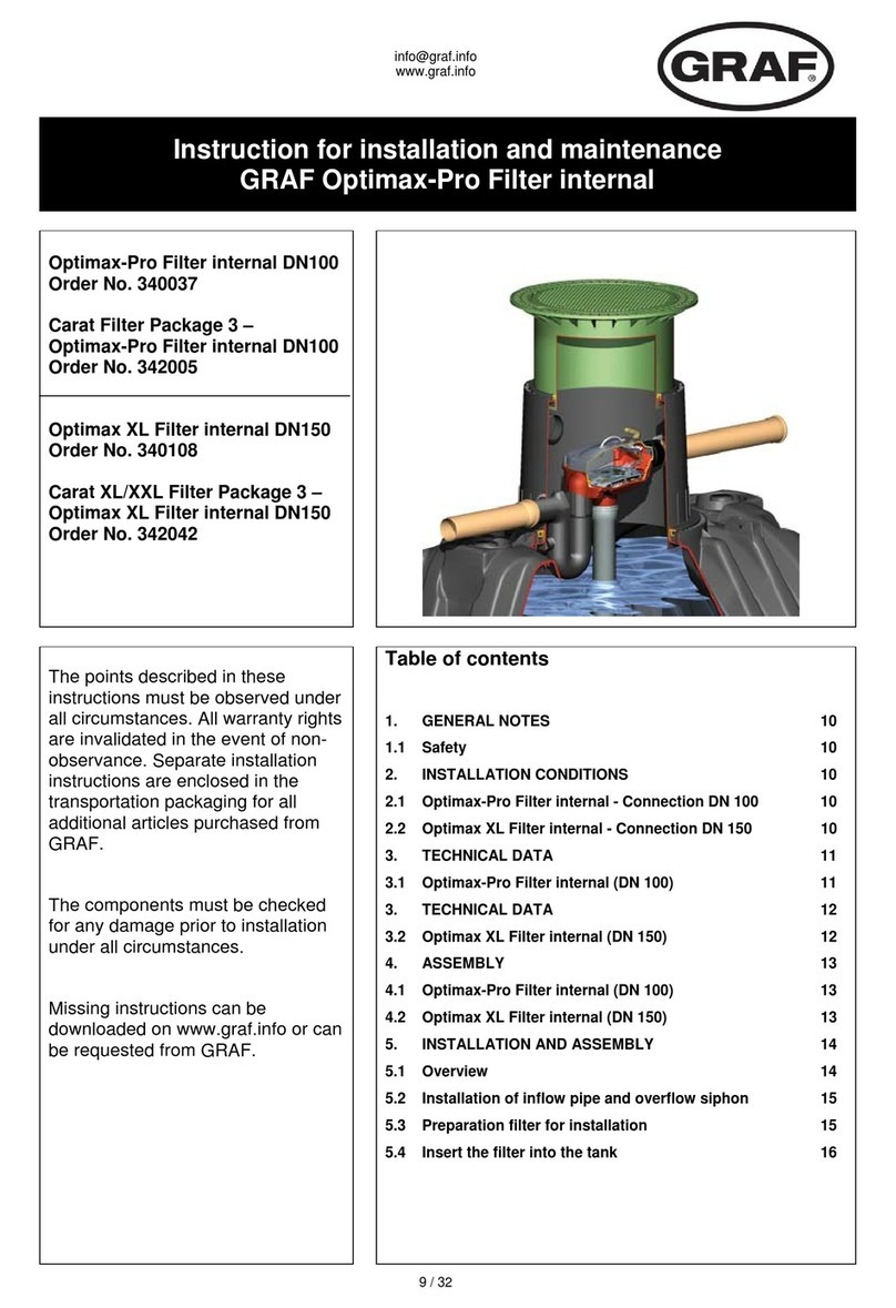
6.2 Maintenance Procedure
As a functional test, a pressure loss measurement for the flow resistance can be carried out.
Recommended limit value for a contaminated filter cartridge: 0.8 to 1 bar, maximum 2bar
• Close ball valves upstream and downstream of the filter. Depressurize the filter.
• Dismount the cover (item 12). To do so, unscrew the Allen screws (item 13) on the cover. Exception for DN 25:
Unscrew cover (item 12).
• Remove O-ring (item 11) inside the housing or cover. Clean the O-ring groove and insert a new greased O-ring
into the groove.
• Pull out the filter cartridge (item 10) towards the top and check whether it is dirty. If necessary, the filter
cartridge must be cleaned or replaced.
• For DN 150 / DN 200: Dismount the spacer (item 17). To do so, unscrew the Allen screws (item 13) at the
spacer. Remove the O-ring (item 11) from the housing (item 1) or from the spacer.
To lower the dismounting dimension for nominal widths DN 150 and DN 200, the filter cartridge and
the spacer should be removed together.
• Clean the O-ring grooves and insert new, greased O-rings into the grooves.
• Pull out the valve seat (item 8) towards the top. (does not apply to DN 100)
• Remove the O-ring (Pos.7) for sealing the valve seat. Clean the O-ring groove and insert a new greased O-ring
into the groove. (does not apply to DN 100)
• For DN 25 / DN 100: Remove the O-ring for sealing the filter cartridge (item 9). Clean the O-ring groove and
insert a new greased O-ring into the groove.
• Dismount the lid (item 5). To do so, unscrew the Allen screws (item 6) from the cover. It may be necessary to
clean the cover.
• Remove the O-ring (item 4) from the housing (item 1). Clean the O-ring groove and insert a new greased O-ring
into the groove.
• Remount the cover (item 5). To do so, screw down the Allen screws (item 6) at the lid crosswise, using a torque
wrench.
• Press the valve seat (item 8) back into the housing passage. Place the cleaned or new filter cartridge (item
10) in the valve seat. The filter cartridges DN 25 and DN 100 comprise a centring ring at one end guaranteeing
the correct fit of the cartridge in the valve seat. During installation, the centring ring is located at the bottom
inside the filter.
• For DN 150 / DN 200: Mount the spacer (item 17). To do so, screw down the Allen screws (item 13) at the spacer
crosswise, using a torque wrench.
To lower the mounting dimension for nominal widths DN 150 and DN 200, the filter cartridge and the
spacer should be inserted together.
• Insert the cover (item 12) and screw down the Allen screws (item 13) crosswise, using a torque wrench.
Exception for DN 25: Screw in cover (item 12) and tighten it, using a torque wrench. When screwing in, exert a
slight pressure on the cover. The filter cartridge is oversized and, due to the leak tightness to be achieved, it
must be compressed somewhat.
• The maintenance parts in the differential pressure measuring instrument are only replaced when necessary.
• Open the valves and fittings upstream and downstream of the filter for leak tightness (using a foaming agent).
To guarantee smooth operation, we recommend always keeping a maintenance set in reserve.
Note
Note
Note
Note


