MEDIA TECHNOLOGY SYSTEMS PERFORMER User manual
PERFORMER

Table of Contents: Page
PERFORMER
Safety Instructions
Introduction & Overview
Quick Start Guide
Features & Functions
Block Diagram
Network Return
Dante
AES67
Control Panel
Connector Panel
Setup Examples
Guitar 1
Guitar 2
DJ
Mall
Function Room
ADR Example
Case
Specifications
Warranty
CE & FCC Approvals
Settings History Log:
1
2
3, 4, 5
6,7,8,9,10
11
12
13
14
15
16
17
18
19
20
21
22
23
24-25
26
27, 28
29
Owner/User Manual MTS Performer rev. 01

PERFORMER
Owner/User Manual MTS Performer rev. 01
IMPORTANT SAFETY INSTRUCTIONS
1. Read these instructions.
2. Observe all warnings
3. For safety and best results, follow these instructions
4. Keep this device away from water and other fluids
5. Install using manufacturer’s instructions in a cool, dry place
6. Use only with approved and certified P.o.E. switches and
devices and follow those manufacturer’s instructions and safety
warnings.
7. Use only qualified and approved service providers
8. Observe all national, state and other government
regulations on earth/ground connections
9. This product complies with Part 15 of the FCC Rules.
Operational conditions:
1. This device may not cause harmful interference.
2. This device must be able to receive interference and
operate normally.
Safety Instructions:
Page 1

PERFORMER
Owner/User Manual MTS Performer rev. 01
Operating manuals are generally not a source for a satisfying literary experience.
Many can be sparse and uninformative or downright painful. With this manual,
we have tried to make the introduction to the Performer an enjoyable and
informative experience. For the novice user, we try to communicate useful
technical information, advice, and history to make your use of the product more
effective. For the seasoned professional, we re-affirm the standard procedures in
which you have invested considerable time and effort learning and applying. We
hope you will enjoy this manual, be informed and get the best results in your use
of the Performer.
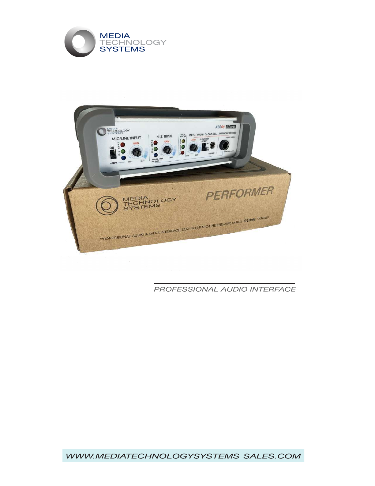
Welcome to this multi-function, ‘Di-Box’ Pre-Amplifier, Professional Audio, Dante
Network Interface. Experience and care have been invested in the specification,
design, functions, choice of components and overall quality of this product.
Our team has decades of hands-on experience in the design, operation,
application and use of recording, production/post production, live sound and
installed systems across thousands of stages around the world. This experience
has been applied to every aspect of this product in order to bring you the best
operational performance and value. This manual describes the features,
functions and set up procedures for the Performer interface.
The MTSI Performer features two pre-amplifier stages optimized for specific
applications, but flexible enough to provide a wide range of sources with low
noise, high quality inputs. The Mic‘ input of the Mic/Line combo socket is suited
to professional quality dynamic and condenser microphones. Using the 1/4” TRS
connector the Line-In is suited to professional ‘balanced line’ sources with
+4dBu nominal levels. These pre-amps offer 20dB of headroom at any gain
setting giving optimum headroom and noise performance. Headphone
monitoring of the inputs is available on the control panel further easing set-up
and use. The low noise and headroom capability of these pre-amps is illustrated
by the ability of the Line-In pre-amp to accept the direct output of a power
amplifier, or a 70/100 Volt distributed system tap. Applications where this
capability may be useful are found later in this manual. The Hi-Z input is
optimized for sources such as a typical Strat’, Tele’, Les Paul guitar inductive
pickups, which like to see 1meg Ohm load impedance in order to maintain their
natural frequency response. As the start point of your sound these inputs
provide an exceptional and flexible solution for high quality audio, whether used
in recording or live sound. Where Dante offers significant advantages in
installations and live sound, it is still finding users and fans in the computer
audio/home-project studio. The Perfomer offers a number of benefits in
headroom, sound quality and flexibility that commend it to this application
regardless of the use/need for Dante networking.
Introduction & Overview:
Page 2

PERFORMER
Owner/User Manual MTS Performer rev. 01
Quick Start Guide:
The Performer is powered ONLY via a “Power over Ethernet” source. You will
need either a P.o.E. enabled switch or P.o.E. Injector device. P.o.E. power is
carried over the standard Cat5e or Cat6 cable. When connected and active the
P.o.E. ON LEDs will illuminate. For your convenience, this indication is
duplicated, on the front and rear panels.
Take all the usual precautions when setting up a system. Start with controls and
levels at their minimums. Using an Ethernet connection with P.o.E. connect your
device and confirm power and status via the Status LEDs.
Connect your instrument and/or microphone, and if required by a condensor or
electret mic’ select the +48V phantom power ON. A Blue LED will illuminate. If
connecting between a guitar and instrument amplifier, insert the cable from the
instrument into the Hi-Z 1/4” input, and a cable from the Thru-Out socket to the
instrument amplifier. Note: Where possible alway use high quality Hi-Z (two
conductor, tip & sleeve) instrument cables of the shortest length that will work for
your application. Cheap, long and curly cables can induce considerable high
frequency loss and compromise your sound. For stage monitor and/or house
mix and recording, connect the Di-Out to the input of a mixing console, or other
device. The Di-Out outputs a nominal +4dBu signal sourced and following the
Monitor Select Control selection. Make sure, if you are checking inputs with the
‘phones function, you return the Monitor selection to the desired source.
With the monitor level at minimum, connect your earbuds or headphones to the
1/8” minijack and select the input you are setting up. While the musician, vocalist
etc., is ’working’ the mic/instrument, ideally at real performance levels, raise the
gain of the input clockwise until you see the Green LED fire, from there as you
increase the gain, depending on the signal dynamics, you will see the Red LED
fire. OK, now bring up the ‘phones level to where you are able to comfortably
hear the quality and integrity of the source you are setting up. Again, always try
to get the performer to give you levels that will apply during the gig/performance.
You do not want any nasty surprises when you are out at the house console!
Note: In the event of a hum or buzz from a ground loop, chase down the problem
thoroughly before resorting to using any ground lift switch or plug. These are
useful tools if needed, but it is always better to work out where the grounding
anomaly is being caused. Safety is of the utmost importance in sound systems
use and the random lifting of grounds is dangerous. For example, an ungrounded
guitar amp on a different, maybe badly wired a/c circuit to the main sound
system, can connect the guitar player holding the guitar neck in one hand and
then touching the mic with the other to 120/240Volts through their body. This is
actually the worst place, one hand to the other with the heart in the middle!
Page 3

PERFORMER
Owner/User Manual MTS Performer rev. 01
Quick Start Guide: cont.
OK, we are now up and running with good signals set to give low noise, and safe
headroom. When you are using this device in a networked system, check that
the Dante output is passing signal to the network. To use the Line Level Return
from the Dante ‘network assign/address the Performer as needed. When you
have an audio signal returning from the Network, the “Return Sig Present” LED
will fire. This is useful, since it indicates there are audio signals on the return and
not just a connection.
Di-Box: What does it do?
What is a Di-Box? Firstly D.I. stands for “Direct Injection”. Why? Traditionally all
instruments just did their thing acoustically. The public started demanding big
bigger bands and louder music for the large dance halls of the day, the weakest
‘instrument’ was typically the human voice, so Public Address Systems were
used. P.A.Systems were by definition, for speech only bandwidth and quality, i.e.
not much warmth and low frequency ability. A similar story existed with Jazz
bands. To hear the arch-top Gibson and D’Angelico guitars, in the bigger
venues, someone converted a Zenith radio console and added first a mic’ then
later a pickup to a guitar. Thus the “instrument amp” was invented and magically
the guitar had a chance to keep up with a reed and horn sections. But wait, now
the Double Bass - ‘bull fiddle’ needs help to keep up with the guitar, so bass
guitars and amps were developed. Ever tried carrying a ‘bull-fiddle’ around on a
tour bus, that alone was enough incentive to develop the P-bass or J-bass! Les
Paul’s Les Paul and Leo Fender’s Broadcaster ‘electric’ guitars were solid body
evolutions from the resonant box, feedback prone, acoustic instruments. These
too more and more demanded a specialized guitar amplifier. Moving on a
couple of decades, as the PA, public address systems had become bigger and
more capable, again instruments weren’t loud enough directly off the stage, or
didn’t cover the whole audience. So, sound engineers used microphones to
bring the guitars etc., to the main P.A., system. Which with their significantly
increased low frequency capabilities were being called “Sound Reinforcement”
Systems, after all, we were not really ‘addressing’ the public any more, we were
amplifying – reinforcing everything in the band to fill bigger and bigger
rock-n-roll venues. Next, depending on the microphone, position etc., musicians
often complained that their instruments didn’t sound right or as good through
the PA/SR System. So a bright guy thought! I know, I’ll make a box to plug the
instrument cable into and then connect that directly to the mixer! Which is how
we get the words “Direct Injection”. Ideally a Di-Box will take the signal going
to the amp’ without compromising it’s quality, possibly bring it up to line level
and present the signal for use in the rest of the system. Ground Lifts, isolation
transformers, gain stages, differential balanced outputs, etc. were developed to
keep things as clean and high quality as possible.
Page 4

PERFORMER
Owner/User Manual MTS Performer rev. 01
In recording and hi-end Sound Reinforcement applications, good results can be
achieved by mic’ing the instrument amp’s speakers AND blending a Di-Box
signal, direct from the guitar. One of these feeds is typically super clean and
carries the ‘instrument’ alone character. However, this is considered somewhat
sterile and “dry” and not representative of the sound the musician seeks and
hears on-stage. So, to add the ‘euphonic’ coloration and character of the
instrument amplifier with it’s spring reverb, tube distortion, cone-cry and any
other effects pedals being applied, we capture the sound from the speaker.
Mic’ing the amp, taking the direct input and mixing them can give great results.
The Performer provides another option, in that it can take a feed directly from
the amp’s output terminal/connectors. See the examples section of this
manual. Any way of creating unique and interesting sounds is certainly worth a
try.
Note: ‘Classic’ traditional style electric guitars, Strat’s, Tele’s, Les Pauls, SGs
mostly have what are called passive inductive pickups. These typically have a
high source impedance, greater than 1kΩ at DC and about 10kΩ at 1kHz. Why
is this important? Some cables are good, some not so good due to differences
in the capacitance between the conductor and the shield inside the guitar cable.
A good quality, low capacitance cable avoids a roll off of high frequencies, before
your signal even gets to the amp. Even on good cables over a longer distance
you can still hear this roll off in HF energy. The old curly cords, spiral cables
intended to let you roam the stage more easily without getting tangled are much
longer in conductor terms than a cable of the same un-stretched length and will
roll off highs. Microphone cables are designed for balanced, low impedance
applications, typically 600Ω or so and ‘see’ an input of less than 10Ω. In this
application the capacitance of the cable is less important. However, if you were
to use this type of cable, that capacitance would result in significant high
frequency loss when using as a guitar cable.
The idea is to get the best possible signal to the amp where you can make your
creative level, EQ, tonal and load/overload decisions using the amp’s controls
rather than having a cheap cable make some of those decisions for you!
As said elsewhere in this document, and as Jack Black indicates in “Make it
Loud” there are no absolute rights and wrongs in sound. It’s all subjective and if
you can get great sound your way, fantastic! We encourage experimentation and
learning from trial and errror. Having a very flexible and useful interface like the
Performer helps in giving you more opportunities to test.
Quick Start Guide: cont.
Page 5

PERFORMER
Owner/User Manual MTS Performer rev. 01
Features & Functions:
Pre-Amps: A general overview...
Lets take a moment to discuss philosophy of design and operation: As far as
our senses are concernced we live in an analog world. Computing,
entertainment and communications today exist almost exclusively in the digital
domain. Certainly there are hold-overs from the analog age, such as black
plastic records, turntables, tube amplifiers and speakers. Many are beloved,
desirable and arguably give superior sound quality. More power to those that
love that technology, we hope it will be available forever. However, there’s a
point in all of today’s entertainment technologies where analog signals meet the
digital world. When recording, to minimize noise and signal degradation, it is
advisable to go from the A to the D domain at the earliest possible stage.
Traditionally one would listen to a Stradivarius violin or Bosendorfer Concert
Grand directly with your ears. When recording those sounds are captured and
stored, ideally without change or loss, then returned later to the ‘air’ and our
ears. To do this well, critical decisions must be made in any specific recording or
live sound situation. All audio technology involves making compromises of one
type or another, understanding the smart choices in a particular situation, is the
key!
Recording a world class artist with a $2.00 microphone, into a 60’s cassette
recorder is not going to get results that are worthy of you, the recording
engineer, the talent or the desires of the audience.
Assuming we have our incredible and expensive microphone and are
connected, how best to proceed? Considering the huge potential dynamic
range an open mic can ‘see’, the gain setting of the pre-amp becomes super
important. Luckily we usually ‘know’ the sort of signal level we are going to
experience and can approximate where we need to be in the dynamic
‘envelope’. The risk comes in when using typical pre-amps that clip hard and
clip objectionally, where to avoid performance destroying crashes you have to
set your gain lower. Then in the mix, raise levels adding those ‘dB‘s’ back as
noise. Thus, in-use an “on-paper’ supposedly quieter pre-amp is noisier than a
higher headroom/soft clip design. Experience shows that exceptional
headroom and soft clip characteristics will achieve considerably higher quality
recordings and live performance sound. As mentioned later in this manual,
small considerations made in design, can make big differences in the‘product’ -
your sound! For example, using an oversize capacitor in the Phantom power
circuit, prevents speaker destroying thumps when the +48V phantom is
accidentally turned on to an open channel! Cost, next to nothing, the result, a
happy audience and surviving speakers, a disproportionate result! You have
already, or will gain experience like this. It is a huge part of the skill and artistry
you bring to the game.
Page 6

PERFORMER
Owner/User Manual MTS Performer rev. 01
Features & Functions: Cont.
What’s this all about preamps clipping hard or any other way? When driven hard
or near their limits, circuits can transition from normal sweet sounding operation,
instantaneously to catastrophic overload. There is no guarantee that even the
best, lowest noise preamps will overload gracefully. They may or may not. Either
way, to be safe you are forced the gain lower to avoid hitting that clip point, and
therefore end up raising the noise in your system.
Given a really good preamp, ideally one with graceful overload characteristics,
the best setup for optimum S/N and safety from clip is found in understanding
the dynamic envelope of your source. Average to Peak ratios of instruments
vary wildly! Woodblocks, snare drum, “more cowbell” etc., have high dynamic
range but low average levels. On the other hand, a trombone or a Cathedral
organ can have high average but low dynamic range. The ideal setup for each
can be understood using the visual indication the Signal Present and Peak LEDs
provide It’s important to understand the LED is labelled PEAK not CLIP.
Typically in the Performer, and depending on the signal type, there’s 6dB or more
usable headroom above the Peak LED firing to the onset of Clip. As you set up
the gain, nudge into the PEAK and occasionally into clip so you can judge the
best setting. Since the Performer is a soft clip design, depending on the signal
type, it may be difficult to actually hear where that transition actually takes place.
The Line, Mic and Hi-Z preamps are similarly designed to give operationally
superior signal to noise, headroom and sound quality.
Noise:
One important factor: The lower the inherent input noise, the better potential
headroom one can achieve. System noise is determined by a number of factors
including the amount of gain, the quality and complexity of the circuitry in
rejecting hum, buzz, external spurious electromagnetic and other noise. The
spectrum of the noise can have a large effect too. These are typically all spec’d
under a heading called EIN. Equivalent Input Noise. Everything, all matter is
made of molecules that according to their temperature are boogying around,
Brownian Motion. In a resistor, this noise is defined by its resistance value. Most
mics and preamps like to see around 150Ω source which is the resistance value
typically used to measure a device. The inherent ‘self noise’ of such a resistor is
around -130dBm. Regardless this is the baseline EIN of a mic preamp. If we
were to freeze the reference resistor to close to 0 degrees Kelvin we could
improve on that number which is done in things like the Hubble Space Telescope
using HEMT, high electron mobility transistors, and cryogenically cooled
amplifiers! Not exactly something we are going to do in our application, but it
illustrates the point. EIN is not, as described here a simple definer of in-use mic
pre-amp inherent noise. It’s easy to compare paper specs, but the real world
can demonstrate considerable differences to your ears.
Page 7

PERFORMER
Owner/User Manual MTS Performer rev. 01
Features & Functions: continued
Noise: continued.
More on pre-amps. Specs are important, but your ears and the word of mouth
referrals from friends are the most valuable ways to make a decision as to what
to buy and use. Understanding specs and how they are derived and what they
mean is not a simple exercise. Raw numbers can be misleading.
A critical factor in the real world performance of a pre-amp is again the
relationship of a number of factors, meaning that a really good EIN number may
not translate into lower noise in use. If that device clips hard and immediately
it sees even a fraction too much signal, then you would need to use a lower
setting and add gain later in the chain, and with that gain you add noise. Being
able to push a signal harder into the pre-amp whilst maintaining its musicality
and integrity, results in readily apparent benefits. Other factors contribute to
noise, given you are using a high quality pre-amp, and regardless of cost and
you are happy with it, let’s discuss microphones. Small mic’ elements
compared to large mic’ elements are inherently noisier. The air, in pressure
waves, transfers energy to a microphone‘s diaphragm moving it back and forth.
How efficiently that movement is converted, ‘transduced’ into electrical energy,
- a signal, relates to the noise of the mic and more importantly to how much
gain (and noise) you have to add to get the levels you require in the mix. The
bigger the diaphragm, all things being equal, the more efficient the conversion
of air motion - energy, typically measured in Pascals. However, large element
mics, have a directivity factor to consider. The larger the diaphragm, the more
directional it will become at higher frequencies. Some like this character in a
mic, calling it “reach” or an increased directivity with increasing frequency.
Because, the directivity increases at higher frequencies, the mic inherently
‘hears’ less off axis sound. This effect is often seen as beneficial, - euphonic,
meaning a pleasant or desirable sonic result. These may or may not be
negatives depending on your taste or application, but large element mics have
one advantage, they are more efficient at converting sound which means you’ll
need less gain and with that, lower noise. Check out some of the small, lavalier
type mics specifically designed for close drum mic’ing. They mostly have poor
noise performance, which for their application is not a problem, since they are
going to be inches away from a drum skin with a wild man beating on it. Hence,
little need for gain, and inherently low noise recordings. In truth, most of
today’s music and recording does not use high gain settings where noise is a
real concern. Again, as with all sound, understanding your goals, the choices
you have to make and what compromises are acceptable to get a great sound
is a huge part of the “art”.
Page 8

PERFORMER
Owner/User Manual MTS Performer rev. 01
The corollary of this is the small “Lavalier” type mic. Small, easy to place with
minimal visual impact for on-camera work, but inherently noisier than a large
element mic. These compromises can be acceptable for certain applications. All
this great spec’manship and sincere efforts towards making a better pre-amp,
result in a complicated marketplace which can be tough to interpret in terms of
“I read the spec’ but how does it benefit me?” A great deal depends upon
defining your needs. If you are recording sparrow burps at thirty paces, noise is
going to be a challenge. If you are close mic’ing a Fender Twin Reverb speaker
with a Shure SM58, 6” away from the cone, or a kick drum with an RE20 buried
inside, not so much!
Most of the microphone products on offer today are really very good and the
variety of different types, sizes, uses are infinite. Assuming you have chosen a
mic’ and all things being equal, it can be about how the pre-amps are used.
A live stage can be a tough environment where once the audience is in,
excitement and passion runs high. You set up, do the sound check and
everything’s fine. The band get back to the hotel for a shower and nice dinner but
you get to stay behind and chase down hums and buzzes, then it’s suddenly its
‘Show Time’. Everyone’s excited, the wine and beer, cognac and ‘other stuff’ in
the Green Room have taken their toll and the drummer hits harder, the lead
guitarist cranks it to ‘11’, the vocalist starts channelling his inner Stevie Marriot
and levels are way up from sound check. Can you get to the pre-amps out on
the stage? Maybe not, but if they have headroom and graceful overload
capabilities, the gig can go on and things will still sound great. The alternative is
higher noise levels from safer lower gain settings at the pre-amp and higher gain
at the console. How you set up a device is important and how it transitions from
normal operation to potential overload is critical. Setup is made easy by having
sight of the dynamic envelope your source represents. Average to Peak ratios
are the issue. Woodblocks, snare drum etc., have huge dynamic range and low
average levels. A trombone or organ can have high average and low dynamics.
The setup for each is simpler when you can see the average via the signal
present LED behaviour and the peaks by the Peak LED. It’s PEAK not CLIP
which is important. Typically and depending on the signal there’s 6dB or so
above the Peak to the Clip. So you have an indication of headroom there too.
Features & Functions: continued
Page 9

PERFORMER
Owner/User Manual MTS Performer rev. 01
Features & Functions: continued
Phantom Power:
Your Performer has professional spec +48V phantom power so can support a
wide range of professional microphones and in particular large element
condenser mics such as a Neumann U47.
The IEC (International Electrotechnical Commission) ‘standard’ IEC61938:2018
specifies microphone phantom power delivery in three ways: P12, P24 and
P48, being 12Volt, 24Volt and 48Volt specs. In each case the standard
specifies, power is to be limited to 240mW.
Sound Quality:
Simply a good preamp set up well for the circumstances should sound great. If
it doesn’t something’s wrong somewhere. Harsh, strident or soft and ill defined
are but a few adjectives used to describe sound quality. Some are to do with
overloads. Some are poor design. A good preamp should sound like nothing at
all. It really shouldn’t add or detract from the sound you are trying to capture.
If it does add a character or sound quality to the signal and this is desired, OK.
In principle it can be better to do this in ‘the mix’ and post processing, rather
than add something that later you may or may not wish for. Either way,
subjective choices are what music, recording and performance are all about!
Page 10
PERFORMER
Owner/User Manual MTS Performer rev. 01
Block Diagram (case top panel illustration)
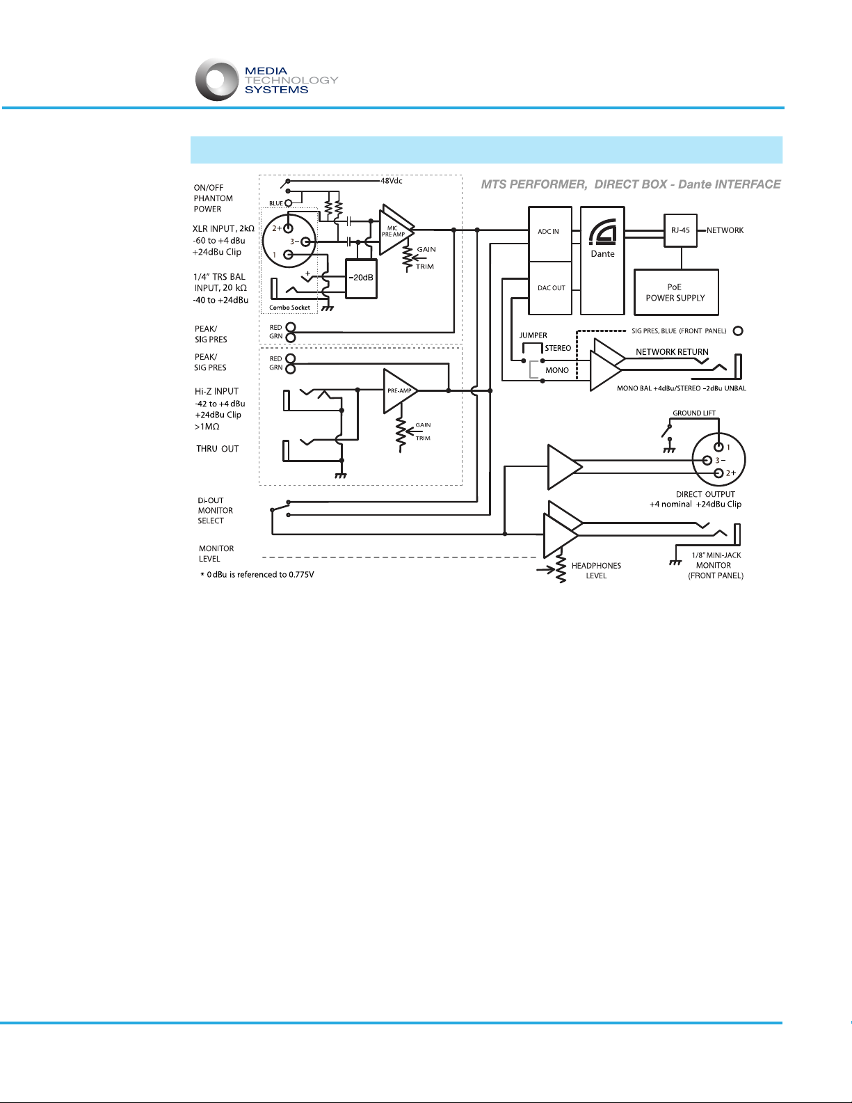
Block diagram (as supplied on Performer top panel) explained:
How to read a functional block diagram, or at least this one! Basically inputs flow
from the left to outputs on the right. Such ‘block diagrams’ are not intended to
be a complete picture of the product, but more of a simplified representation of
the signal flow and control functions. On left margin are descriptions of the
inputs and controls including impedances, nominal and max levels, gain range
etc. Check where you intend to connect, confirm impedances and levels are
suitable for your source, then follow the signal path through the device to the
output you wish to use. For example: On the Mic/Line input, the XL ‘Mic Input’,
depending on gain setting, can be seen to have +24dBu max input capability.
Line inputs, not needing the gain capabilities of a mic input, show the ‘Line Input’
with an internal -20dB pad, before the preamp, showing how it is able to accept
up to a +44dBu input level! The diagram further shows the phantom power is
only available at pins 2 & 3 of the XL connector. You can also confirm that the
Performer follows the accepted standard for Pin 2 High/Positive on an XL
connection. The block diagram can be very useful in helping to trouble shoot
system problems.
Note: The jumper function converts the Network Return 1/4” TRS output from a 2
channel - ‘stereo pair’, -2dBu nominal, to a single channel/mono balanced +4dBu
nominal output.
1
2
Page 11
PERFORMER
Owner/User Manual MTS Performer rev. 01
Network Return:
The Performer’s Network Return function, exactly as it implies, outputs two
return feeds from a Dante network. This useful feature can be configured in either
of two ways.
1. The default setting: A two channel (Stereo) Pair, i.e. Two discrete line level
channels routed back from the Dante network, converted to analog and available
at the front panel Network Return ¼” TRS ouput.
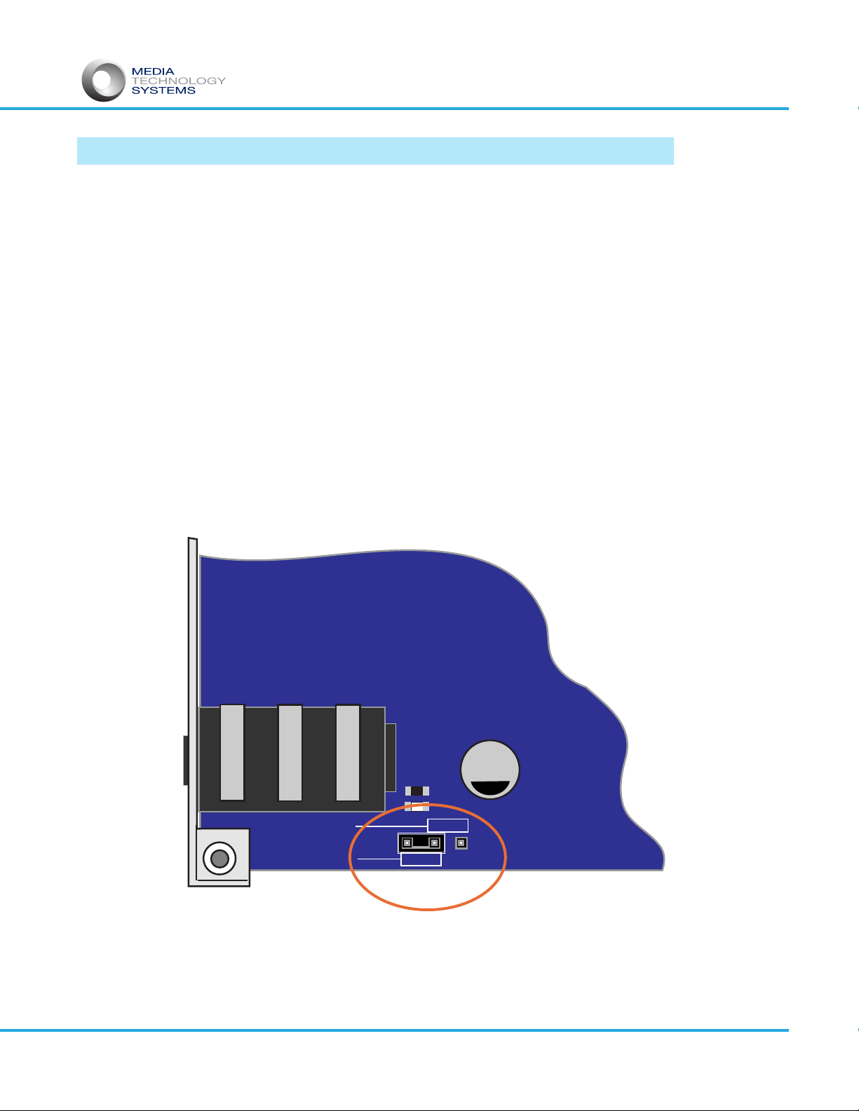
2. Alternatively a PCB jumper can be moved to configure the channel 1 Network
Return to single channel Balanced Line Out, +4dBu.
Note: The Network Return ouput(s) are capable of directly driving most quality
wired headphones/ear buds to acceptable levels. However, there is no local
volume control on this output.
Re-configuration of the Network Return internal routing should only be
performed by qualified/authorized personnel. See warranty section.
Page 12
MONO BALANCED
Network Return
Output Selection
STEREO UNBAL.
CONTROL
PANEL
NETWORK
RETURN
OUTPUT
COMPONENT SIDE OF PCB
G7
22
50J
C115
L5
To change Network Return Output from default factory setting, 2 channel
unbalanced, to single channel balanced out, remove jumper from the left and
center pins, and re-position to the center and right pins, as shown below.
Note: Take care to identify on the outside of your Performer that it is
re-configured from the factory default setting to mono-balanced line out.

PERFORMER
Owner/User Manual MTS Performer rev. 01
Dante™
Your Performer Di-Box features high quality pre-amplifiers and A-D’s
converting two discrete channels to digital audio routed over a Dante
enabled network. In addition to the Hi-Z input normally provided in
a Di-Box, the high quality Microphone/Line Input pre-amplifier
circuitry gives another opportunity to channel an additional audio
source to Dante enabled mixer, recording/storage device or any
other endpoint your application requires. The A-D stage is a high
quality 24bit/96kHz converter feeding two Dante channels to the
network via the RJ45 connector. We illustrate example situations
and applications in this manual, but for now let’s look briefly at Dante
theory and operation.
Nothing needs to be done in your Performer to set up Dante
operation. Dante Network Controller gives the user control and
management of all Dante enabled devices on a network. Audinate™
the developer of Dante provides software allowing you to manage all
Dante enabled devices across a network. Dante controller can be
downloaded free of charge from www.audinate.com.
We suggest you familiarize yourself with the Audinate site and Dante
technology. This excellent site has a wealth of readily accessible
and valuable information on Dante and its use.
Connect your MTSI Performer to the network and it will appear as an
available transmit device within Dante Controller. Dante Controller
allows you to personalize/give your device a specific name. It is
advisable that you record your specific unit’s MAC address.
Firmware Update:
In addition to Dante Controller the Dante firmware can be updated, if
required, by using the Dante Firmware Update Manager software
available at my.audinate.com/latest-firmware-update-manager.
Instructions are available on the Audinate website. Use Dante
Controller to access your device info and ascertain your firmware
edition.
Page 13

PERFORMER
Owner/User Manual MTS Performer rev. 01
AES67:
AES67 is a published international standard by the Audio Engineering Society,
defining low latency audio interoperability amongst professional audio devices
operating over digital IP networks. This is not a replacement for Dante or any
other networking technology. It however, provides for interoperability between
networked audio over IP technologies, including but not limited to, Dante,
Q-Lan, Limewire, WheatNet and RAVENNA.
The bottom line is, AES67 defines a common standard for all devices to stream
media over a network, so that any device on that network can communicate
with any another. AES67 does not create of define a new standard, it allows for
how to use known and trusted protocols defined under other standards.
AES67 defines the simplest possible features allowing two compliant devices to
exchange audio streams. Although the definitions are minimal, some devices
are capable of exceeding the definitions, for example, a minimum number of 8
channels. Most AES67 compliant devices will exceed the minimum and support
16, 64 or more channels. AES67 further defines timing of packets to maintain
minimum latency.
AES67 does not replace Dante or any other audio over IP technologies. It was
designed as a bridge facilitating communication between different systems.
Page 14

PERFORMER
Owner/User Manual MTS Performer rev. 01
Control Panel, Indicators & Connections.
Di OUT/MON
SELECT
Mic/Line Input:
Phantom Power. On/Off, +48V to pins 2 and 3 of the XL connector
Peak LED. Fires when signal envelope is within 6dB of clipping.
Signal Present LED. Fires when Signal envelope is within 30dB of Peak.
+48V Phantom LED Illuminated Blue = ON
Input Gain Control For XLR connection, -60 -+4dBu continuous gain range,
optimizes signal to noise ratio for 20dB of headroom throughout the
full gain range. No pad? A 20 or 10dB pad will usually either give you
worse noise or less headroom, since 10 or 20dB is an arbitrary
number unlikely to ‘fit’ your actual gain needs.
Note: Using the Mic input XL is acceptable for Line input
use since its input range will accommodate +4dBu nominal sources.
Line Input Balanced line input, -40 to +44dBu input range on TRS
combo connector.
Note:Performer input controls feature 41 position detents
allowing the user to note settings for future reference.
Hi-Z Input: Signal Present/Peak.Function as per the Mic/Line Input.
Hi-Z Gain: For 1/4” TRS connection, per Mic/Line Input, however
-42 - +4dBu gain range.
Network Return Network Return(s) Signal Present, flashes when Signal is
present on the circuit.
For 1/4” TRS connection, per Mic/Line Input, however
-42 - +4dBu gain range.
Mon/Di-Out Sel. Variable level control for ear buds, headphones etc.
Di-Out Select: Routes selected input signal to phones AND Di-Out rear
XL connection.
Network Return: Dante Networked audio return, single ch Balanced Line
or 2 ch “stereo”output. User Selectable via PCB Jumper.
See block diagram. Factory default set to 2
channel/Stereo -2dBu output.
Page 15
PERFORMER
Owner/User Manual MTS Performer rev. 01
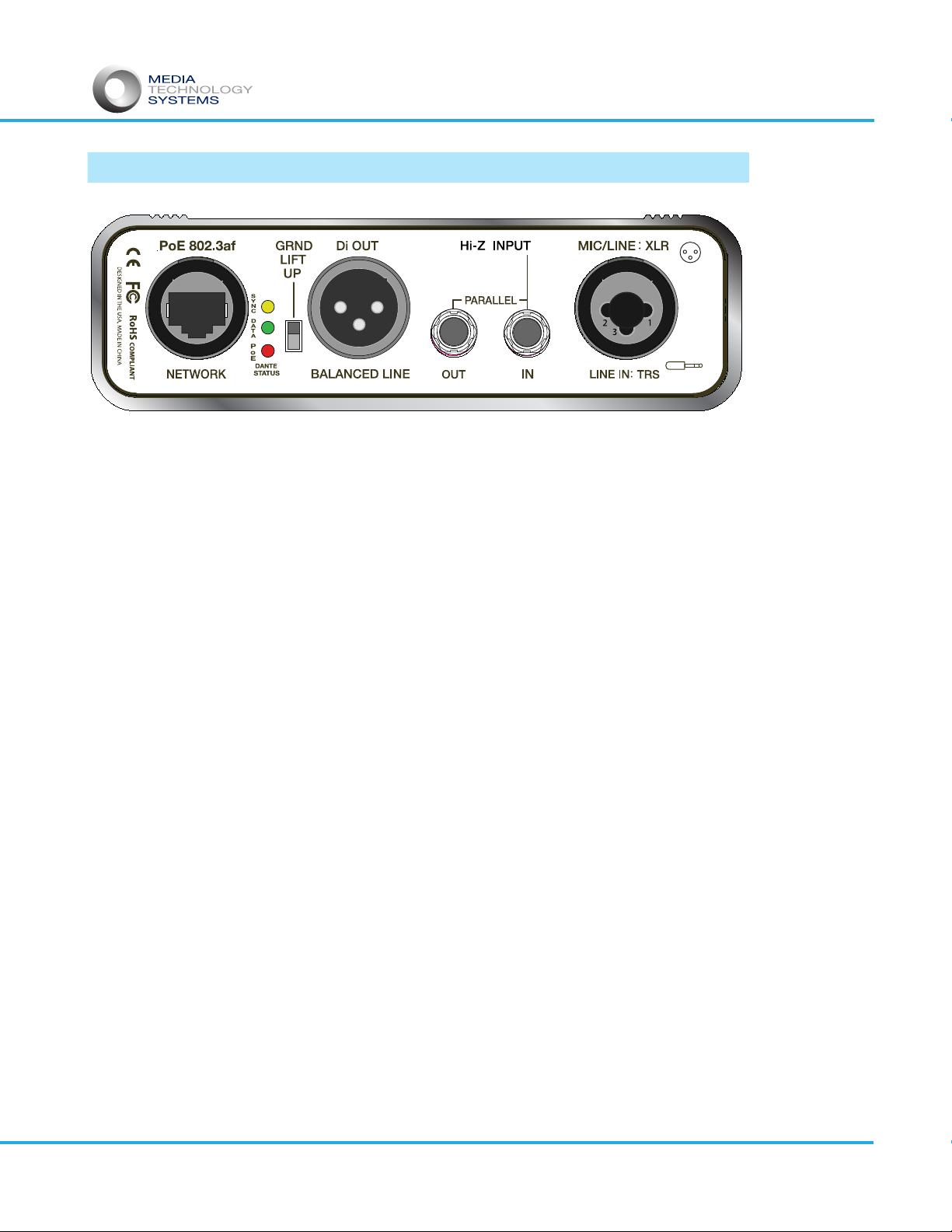
Connector Panel:
Network RJ45. Network and P.o.E. Connection
Dante Status LEDs: Sync/Data, P.o.E. connected and active
Ground Lift Select. UP position the ground,
Di Pin 1 is lifted/disconnected..
Di-OUT, XL connector, non latching.
Hi-Z INPUT.
IN. 1 meg Ohm impedance, ¼” Tip/Sleeve.
OUT. Connects the input to the output jacks.
Note: Although these are parallel inputs,
the circuit uses a ‘switched socket
making only the “IN” connector an input
to the circuit.
Mic/Line XL Input: Combi Connector, XL for Mic, plus
1/4”-TRS Balanced input, Line level.
Note: +48V Phantom Power is only applied
to XL pins 2 and 3.
Page 16

PERFORMER
Owner/User Manual MTS Performer rev. 01
Electric Guitar, example set up:
The Performer, in this simplifed example setup, lets you mix the real sound of
the guitar rig, i.e. the overall combined tone of the guitar, effects pedal,
amplifier and speakers by mic’ing the amp. At the same time connecting the
post effects pedal signal to the Performer’s Hi-Z Input, the through-out
connection going on to the guitar amplifier. This input has an input impedance
of one Meg Ω designed to not negatively ‘load’ the guitar’s inductance pickup
leaving the signal pristine and unchanged whilst extracting the signal for use in
the system at the Dante and/or Di-OUT connections. As shown, the guitar
amp’s speaker is mic’d and routed to the Performer’s Mic input. This
connection path presents both the ‘clean’ guitar signal AND the amplifier’s
desirable “Tone” contributions, tube distortion and speaker cone-cry.
The line level Di-Out, direct output is available as an analog signal for a
traditional (non networked) local stage monitor mix. Remember the Di-Out
follows the Di-Out/Monitor select switch selection on the Performer. The
Network Return output from the Performer, gives you a Dante system return
mix, for example, for in-ear, or powered speaker stage monitoring.
o o o o o o o
. . . . . . . . . . .
. . . . . . . . . . .
EFFECTS
PoE SWITCH
POWERED MONITOR
Dante ENABLED MIXER
INSTRUMENT MIC
Page 17

o o o o o o o
PERFORMER
Owner/User Manual MTS Performer rev. 01
Guitar Amp Setup alternative:
Di OUT/MON
SELECT
. . . . . . . . . . .
. . . . . . . . . . .
PoE SWITCH
Dante ENABLED MIXER
Guitar AMP Di Rig 03152020
SUPER
Rand-O-Matic
Hi-Level/Amp Output
Wired to Tip/Ring on
Performer 1/4” Mic/Line
Input
This example shows a method of capturing sounds from a rig by ‘sampling’ both the
direct guitar signal, plus the character and desirable coloration of the amp & speaker.
The high level output of the amp is taken at the speaker terminals and fed into the
Line Input, who‘s impedance (20kΩ) has no eect on the amp’s output. Take care to
not short the amp connection! With a combo amp this is simple since the speaker box
is typically open back. The idea here is that a direct connection at the speaker
terminals ‘sees’ the “Back EMF” coloration contributed by the speaker. Back EMF is the
added ElectroMotive Force the moving parts of the speaker generate in the ‘motor’ of
the speaker and which appear as electrical energy imposed on the amp‘s original
drive signal. Basically, the amp tells the speaker to move forward. The speaker moves
and intertia and momentum, plus cone breakup and other mechanical artifacts in the
moving ‘system’ ADD desirable coloration to the sound. These added energies in the
speaker generate electrical signals that include the speaker‘s sonic character. To
capture these, the closer to the speaker terminals one can connect, the better, since
the resistance of even a speaker cable will lose some of this signal. Is this the same as
mic’ing a speaker. No, but a more consistent signal will be seen with this method.
Many successfully grab the sound of the amp by mic’ing the speakers which is great
since it ‘hears’ the amp and speaker. However, the position of a closely placed mic on
the speaker cone is super-sensitive to even very small positional dierences resulting
in major tonal changes. In addition it is always a good idea to limit the number of open
mics on a stage.
Special Cable with
Crocodile Clips to
connect directly to
Speaker Terminals
Page 18
Table of contents
Other MEDIA TECHNOLOGY SYSTEMS Recording Equipment manuals


