MediaMatrix nWall User manual
nWall Hardware Manual
Version 1.7.0a.0
January 16, 2014

ii Version 1.7.0a.0 January 16, 2014
Copyright notice
The information contained in this manual is subject to change without notice. Peavey Electronics is not liable for
improper installation or configuration. The information contained herein is intended only as an aid to qualified
personnel in the design, installation and maintenance of engineered audio systems. The installing contractor or end
user is ultimately responsible for the successful implementation of these systems.
All creative content in this manual, including the layout, art design, content, photography, drawings, specifications
and all other intellectual property is Copyright © 2014 Peavey Electronics Corporation. All Rights Reserved. Features
& specifications subject to change without notice.
The ratc-server component is based in part on the work of the libwebsockets project: http://libwebsockets.org.
Prepared by Peavey Digital Research, 6 Elm Place, Eynsham, Oxford, OX29 4BD, UK.
Email:mmtechsuppo[email protected].
Scope
This guide describes how to install an nWall device and how to connect the device to the network.

January 16, 2014 Version 1.7.0a.0 iii
Contents
Chapter 1 Important safety instructions................................................................1
Safety warnings........................................................................................................................................2
Chapter 2 Before you start .....................................................................................5
Important network considerations ............................................................................................................6
Warranty Registration...............................................................................................................................6
What you will need ...................................................................................................................................6
What's in the box?....................................................................................................................................6
Thank You! ...............................................................................................................................................6
Chapter 3 Introduction to nWall ............................................................................7
The nWall..................................................................................................................................................8
Features....................................................................................................................................................8
Example set up.........................................................................................................................................9
Front panel .............................................................................................................................................10
Rear Panel Connections.........................................................................................................................11
Chapter 4 Infrastructure design considerations.................................................13
Introduction.............................................................................................................................................14
2-gang NEMA electrical enclosures .......................................................................................................14
Power over Ethernet solution .................................................................................................................15
IP addresses...........................................................................................................................................16
Chapter 5 Installing and connecting the nWall .................................................17
Installing the nWall .................................................................................................................................18
Assigning an IP address and bundle number.........................................................................................19
Connecting multiple nWalls....................................................................................................................22
Connecting audio devices ......................................................................................................................22
Warranty statement.................................................................................................23


Chapter 1 - Important safety instructions
2 Version 1.7.0a.0 January 16, 2014
.
Safety warnings
Warning: When using electrical products, basic cautions should always be followed,
including the following:
1. Read these instructions.
2. Keep these instructions.
3. Heed all warnings.
4. Follow all instructions.
5. Do not use this apparatus near water.
6. Clean only with a dry cloth.
7. Do not block any of the ventilation openings. Install in accordance with manufacturer’s
instructions.
8. Do not install near any heat sources such as radiators, heat registers, stoves or other
apparatus (including amplifiers) that produce heat.
9. Do not defeat the safety purpose of the polarized or grounding-type plug. A polarized plug
has two blades with one wider than the other. A grounding type plug has two blades and a
third grounding plug. The wide blade or third prong is provided for your safety. If the
provided plug does not fit into your outlet, consult an electrician for replacement of the
obsolete outlet.
10. Protect the power cord from being walked on or pinched, particularly at plugs,
convenience receptacles, and the point they exit from the apparatus.
11. Only use attachments/accessories provided by the manufacturer.
12. Use only with a cart, stand, tripod, bracket, or table specified by the manufacturer, or sold
with the apparatus. When a cart is used, use caution when moving the cart/apparatus
combination to avoid injury from tip-over.
13. Unplug this apparatus during lightning storms or when unused for long periods of time.
14. Refer all servicing to qualified service personnel. Servicing is required when the apparatus
has been damaged in any way, such as power-supply cord or plug is damaged, liquid has
been spilled or objects have fallen into the apparatus, the apparatus has been exposed to
rain or moisture, does not operate normally, or has been dropped.
15. Never break off the ground pin. Write for our free booklet Shock Hazard and Grounding.
Connect only to a power supply of the type marked on the unit adjacent to the power
supply cord.
16. If this product is to be mounted in an equipment rack, rear support should be provided.
17. Note for UK only: If the colors of the wires in the mains lead of this unit do not
correspond with the terminals in your plug‚ proceed as follows:
a) The wire that is colored green and yellow must be connected to the terminal that is
marked by the letter E‚ the earth symbol‚
b) colored green or colored green and yellow.
c) The wire that is colored blue must be connected to the terminal that is marked with the
letter N or the color black.
d) The wire that is colored brown must be connected to the terminal that is marked with
the letter L or the color red.

nWall Hardware Manual
January 16, 2014 Version 1.7.0a.0 3
18. This electrical apparatus should not be exposed to dripping or splashing and care should be
taken not to place objects containing liquids, such as vases, upon the apparatus.
19. The on/off switch in this unit does not break both sides of the primary mains. Hazardous
energy can be present inside the chassis when the on/off switch is in the off position. The
mains plug or appliance coupler is used as the disconnect device, the disconnect device
shall remain readily operable.
20. Exposure to extremely high noise levels may cause a permanent hearing loss. Individuals
vary considerably in susceptibility to noise-induced hearing loss, but nearly everyone will
lose some hearing if exposed to sufficiently intense noise for a sufficient time. The U.S.
Government’s Occupational Safety and Health Administration (OSHA) has specified the
following permissible noise level exposures:
Duration Per Day in Hours
Sound Level dBA, Slow
Response
8
90
6
92
4
95
3
97
2
100
1½
102
1
105
½
110
¼ or less
115
According to OSHA, any exposure in excess of the above permissible limits could result in
some hearing loss. Ear plugs or protectors to the ear canals or over the ears must be worn when
operating this amplification system in order to prevent a permanent hearing loss, if exposure is
in excess of the limits as set forth above. To ensure against potentially dangerous exposure to
high sound pressure levels, it is recommended that all persons exposed to equipment capable
of producing high sound pressure levels such as this amplification system be protected by
hearing protectors while this unit is in operation.
SAVE THESE INSTRUCTIONS!


January 16, 2014 Version 1.7.0a.0 5
In This Chapter
Important network considerations.....................................................................6
Warranty Registration.......................................................................................6
What you will need...........................................................................................6
What's in the box?.............................................................................................6
Thank You!.......................................................................................................6
Chapter 2
Before you start

Chapter 2 - Before you start
6 Version 1.7.0a.0 January 16, 2014
.
Important network considerations
This product is designed to operate on a network backbone or infrastructure. The design,
implementation and maintenance of this infrastructure is critical to correct operation and
performance of the product. Peavey Electronics Corp does not support nor service network
cabling, hubs, switches, patch bays, wall plates, connector panels or any other type of network
interconnect device. Please ensure that these components and their associated installation
techniques have been properly designed and installed for audio and network applications.
Warranty Registration
Please take afew minutes and fill out the warranty registration card. Although your warrantyis
valid without the registration, the information you provide with the form is crucial to our
support group. It enables us to provide better service and customer support, and to keep you
informed of new product updates.
Tip: Refer to the warranty statement at the rear of this manual for details of what your
warranty includes and what the limitations are.
What you will need
Phillips head screwdriver to fit NEMA enclosure screws.
What's in the box?
In the box you will find:
The nWall
Four screws, which are used to securely install the nWall in a NEMA electrical enclosure.
Thank You!
Thank you for purchasing this MediaMatrix product. It is designed to provide years of
trouble-free operation and high quality performance. We are confident that you will find this
product and other MediaMatrix products to be of the highest quality.

January 16, 2014 Version 1.7.0a.0 7
In This Chapter
The nWall..........................................................................................................8
Features.............................................................................................................8
Example set up..................................................................................................9
Front panel........................................................................................................10
Rear Panel Connections....................................................................................11
Chapter 3
Introduction to nWall

Chapter 3 - Introduction to nWall
8 Version 1.7.0a.0 January 16, 2014
.
The nWall
The MediaMatrix nWall is a surface mount CobraNet interface panel with two analog
microphone/line level input channels. The device converts audio from the input channels to a
CobraNet audio stream. It can then be routed via CobraNet bundle transmitters over a local
area switched network using CAT5e UTP cable.
The nWall eliminates the need for long runs of analog microphone cables terminated in racks
of patch bays as typically seen in ballrooms and convention centers. As the connection to the
nWall uses CAT5e UTP cable with network standard RJ-45 crimp connectors, the installation
time, number of terminations required and associated cost are all minimized.
The nWall can be used in numerous places such as hotels, bars and restaurants, schools and
many other venues.
Notes:
If you want to control and monitor an nWall using an NWare project, you will need an
nControl unit or nTouch 180 unit. If you simply want to transmit audio froman nWall onto
the CobraNet network these devices are not required. However, before any connection can
be made you must configure the nWall with an IP address by Using CobraNet Discovery
(on page 19) or by using NWare (on page 20).
The nWall can only be powered via an IEEE 802.3af PoE compliant network switch. This
must provide up to 15.4W of DC power (minimum 44V DC and 350mA) from each
individual port over CAT5e UTP cable.
Features
Two unbalanced TRS 1/8” (3.5mm) mini jack inputs - summed mono for PC and Aux
consumer line level audio products support off the shelf consumer audio cables.
Balanced XLR inputs - mic/line selectable gain via front panel 3 step rotary switch allows
quick source setup at the wall panel. XLR connector is latchless to minimize mechanical
damage to the interface panel.
Digital patching - using MediaMatrix NWare any number of nWall panels can be patched
to any number of NION processors on the fly, eliminating the need for expensive patch
panels and greatly reducing setup time between events.
Analog to digital conversion at the wall panel reduces problems with buzz, hum, ground
loops and other cable issues, also eliminating the need for isolation and impedance
matching interfaces.
Structured cabling to greatly reduce critical path delivery time and costs.
Power over Ethernet (PoE).
Low power requirements.2-gang NEMA mount.
CobraNet audio transport via switched network and RJ-45.
Easy wiring and installation.
Cost effective.
nWall Hardware Manual
January 16, 2014 Version 1.7.0a.0 9
Example set up
The MediaMatrix nWall plate enables conversion from analog audio to CobraNet to take place
at the wall. This eliminates long lines of analog audio cable between a conventional passive
wall plate and the nearest control room rack. Applications would include hotels/hospitality
suites, convention centers, corporate meeting rooms and classrooms.
Chapter 3 - Introduction to nWall
10 Version 1.7.0a.0 January 16, 2014
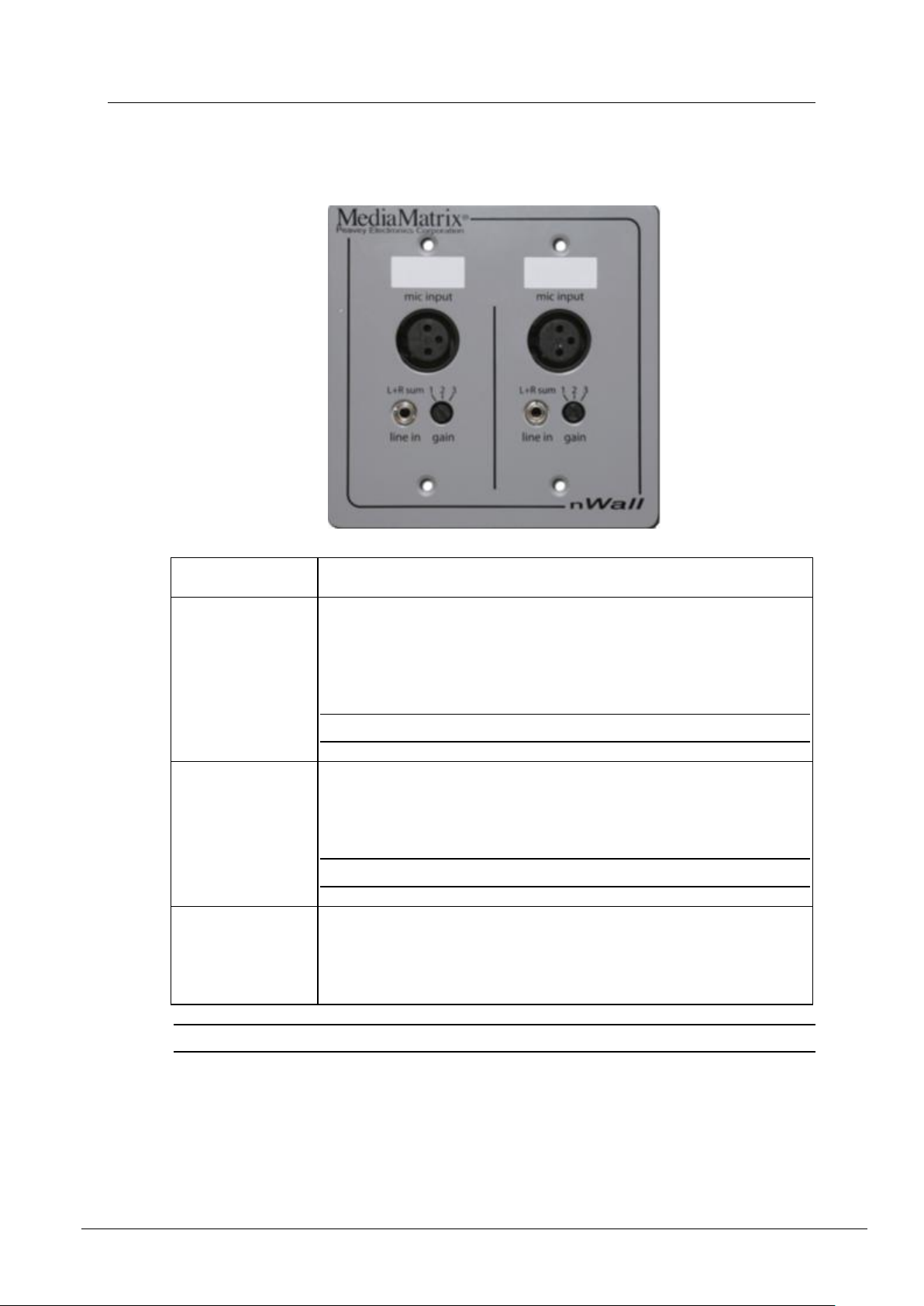
Front panel
Control
Purpose
Mic input
The Mic inputs are two balanced XLR3 (F) inputs. The Mic inputs
receive audio from an audio source device. The input sums the Left and
Right inputs on the mini plug and then sums with the XLR jack after the
gain adjustment.
Note: The Mic input has a line inpendace of 2.0KOhm.
Line in
The unbalanced TRS (F) 1/8th inch mini jack inputs are summed to
mono then mixed with XLR, -8dBu (nominal) +12 dBu (peak). This
input also receives audio from an audio source device.
Note: The Line input has a line impendance for 10.0kOhm.
Gain
Rotary (3 step) switch supports each adjacent XLR. The selectable gain
attenuation levels are: -56dBu / -26dBu / +4dBu (nominal) with
+20dBu (peak) headroom for each setting. This adjusts the gain of the
XLR input.
Tip: You can use the two blank label boxes for custom labeling of each input channel.

nWall Hardware Manual
January 16, 2014 Version 1.7.0a.0 11
Rear Panel Connections
The rear panel contains a LAN socket for CobraNet and control communications on
100Base-T Ethernet. It requires a Power-over-Ethernet (PoE) injector or PoE via an IEEE
802.3af capable network switch.


January 16, 2014 Version 1.7.0a.0 13
In This Chapter
Introduction.......................................................................................................14
2-gang NEMA electrical enclosures.................................................................14
Power over Ethernet solution............................................................................15
IP addresses.......................................................................................................16
Chapter 4
Infrastructure design
considerations

Chapter 4 - Infrastructure design considerations
14 Version 1.7.0a.0 January 16, 2014
.
Introduction
Before you start the installation, it is important to consider the implications for your network
and power supply system. The infrastructure must be designed and installed correctly, in order
to provide reliable and error-free performance.
Each nWall unit requires a network connection to a network switch. A NION must also be
connected via its CobraNet connection to the same network. There are several configurations
you can use, allowing for a degree of flexibility in your installation.
2-gang NEMA electrical enclosures
nWall units are designed to mount in standard NEMA electrical enclosures. This includes
boxes designed for fixed installation into sheet rock, wood or masonry construction. All
cabling and terminations should be installed into EMT conduit, securely coupled to the
mounting box and system ground plane. However, the nWall is not grounded through the
network cable. It should be installed in a metal 2-gang NEMA electrical enclosure that is
grounded according to the directives set forth by the authority having jurisdiction.

nWall Hardware Manual
January 16, 2014 Version 1.7.0a.0 15
Power over Ethernet solution
Power is supplied to the nWall devices via an injector or Power over Ethernet (PoE) switch.
The nWall devices do not require separate power connections. A basic nWall network
example only needs a single nWall, PoE switch and a connection to the Ethernet network.
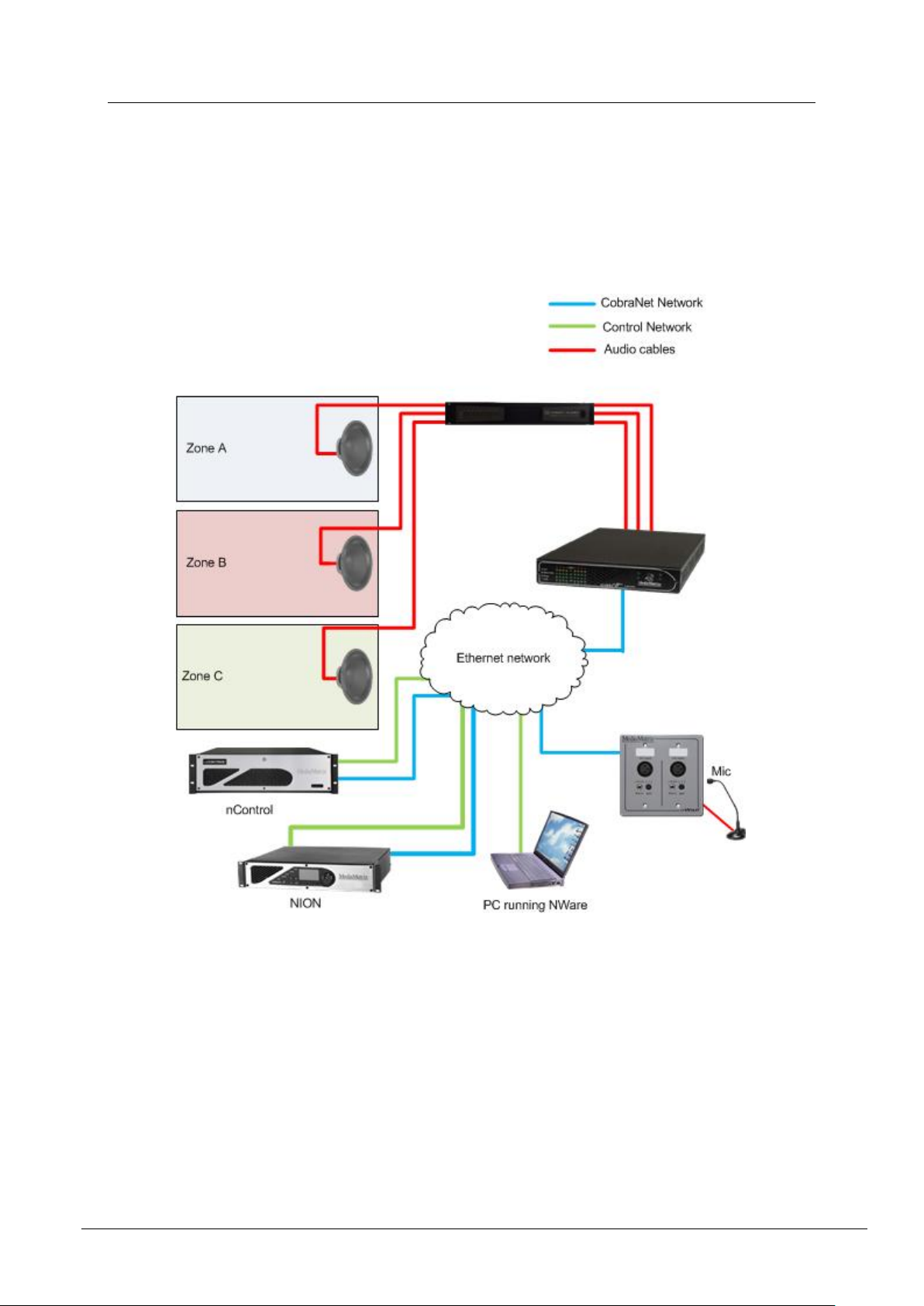
In the example below, three microphones are connected to three nWalls; these nWalls are
connected to the PoE switch. The PoE switch has a direct link to the main Ethernet network.
This allows a PC running NWare to use the deployed project to allow audio to pass through the
Crest Amplifier and out of the loudspeaker.

Chapter 4 - Infrastructure design considerations
16 Version 1.7.0a.0 January 16, 2014
IP addresses
Though it is not needed, as nWalls can pass audio by being assigned a bundle number, each
nWall unit can be configured with an IP address, which is used to identify the unit on the
network and also within NWare.
You can use CobraNet discovery to assign an nWall a fixed IP address. For more information,
see Using CobraNet Discovery (on page 19).
Another method that you can use to assign an IP address to the nWall is by using the Agent
Discovery device in NWare. For more information, see Using NWare.
For more information on IP addresses, see Assigning an IP address and bundle number (on
page 19).
Table of contents
Popular Accessories manuals by other brands

Airmar
Airmar TRIDUCER Smart UDST800 owner's guide

Staubli
Staubli PV Series Assembly instructions

weinor
weinor BiConnect BiSens Agido-3V Operating and adjustment instructions

Allen + Roth
Allen + Roth EMERALD COVE PS-213-60-EC Assembly instructions

Infinite
Infinite L-com SRCN-C413-3 user guide

Ecolink
Ecolink WST-621 instruction manual


