MediaMatrix CAB 8n User manual
CAB 8n Hardware Manual
Version 1.7.1.0
July 23, 2014

ii Version 1.7.1.0 July 23, 2014
Copyright notice
The information contained in this manual is subject to change without notice. Peavey Electronics is not liable for
improper installation or configuration. The information contained herein is intended only as an aid to qualified
personnel in the design, installation and maintenance of engineered audio systems. The installing contractor or end
user is ultimately responsible for the successful implementation of these systems.
All creative content in this manual, including the layout, art design, content, photography, drawings, specifications
and all other intellectual property is Copyright © 2014 Peavey Electronics Corporation. All Rights Reserved. Features
& specifications subject to change without notice.
The ratc-server component is based in part on the work of the libwebsockets project: http://libwebsockets.org.
Prepared by Peavey Digital Research, 6 Elm Place, Eynsham, Oxford, OX29 4BD, UK.
Email:mmtechsuppo[email protected].
Scope
This guide describes how to physically install a CAB 8n and configure it with basic settings. It is assumed that you
have installed NWare and are familiar with how to use it effectively.
For information on NWare, refer to the NWare User Guide.

July 23, 2014 Version 1.7.1.0 iii
Contents
Chapter 1 Important safety instructions................................................................1
Safety warnings........................................................................................................................................2
Chapter 2 Before you start .....................................................................................5
Important network considerations ............................................................................................................6
Thank You! ...............................................................................................................................................6
Warranty Registration...............................................................................................................................6
What's in the box?....................................................................................................................................6
Chapter 3 Introduction to the CAB 8n...................................................................7
Description................................................................................................................................................8
Features....................................................................................................................................................8
Applications ..............................................................................................................................................9
Front Panel.............................................................................................................................................10
Rear panel..............................................................................................................................................11
Chapter 4 Installing the CAB 8n ..........................................................................13
Introduction.............................................................................................................................................14
What you will need .................................................................................................................................16
Connections............................................................................................................................................16
Setting the Hardware ID .........................................................................................................................24
Understanding gain structure .................................................................................................................25
What to do next ......................................................................................................................................25
Appendix A Reference Information....................................................................27
Serial communications ...........................................................................................................................28
GPIO overview .......................................................................................................................................29
Technical specifications..........................................................................................................................30
Technical Support...................................................................................................................................34
Warranty statement.................................................................................................37


Chapter 1 - Important safety instructions
2 Version 1.7.1.0 July 23, 2014
.
Safety warnings
Warning: When using electrical products, basic cautions should always be followed,
including the following:
1. Read these instructions.
2. Keep these instructions.
3. Heed all warnings.
4. Follow all instructions.
5. Do not use this apparatus near water.
6. Clean only with a dry cloth.
7. Do not block any of the ventilation openings. Install in accordance with manufacturer’s
instructions.
8. Do not install near any heat sources such as radiators, heat registers, stoves or other
apparatus (including amplifiers) that produce heat.
9. Do not defeat the safety purpose of the polarized or grounding-type plug. A polarized plug
has two blades with one wider than the other. A grounding type plug has two blades and a
third grounding plug. The wide blade or third prong is provided for your safety. If the
provided plug does not fit into your outlet, consult an electrician for replacement of the
obsolete outlet.
10. Protect the power cord from being walked on or pinched, particularly at plugs,
convenience receptacles, and the point they exit from the apparatus.
11. Only use attachments/accessories provided by the manufacturer.
12. Use only with a cart, stand, tripod, bracket, or table specified by the manufacturer, or sold
with the apparatus. When a cart is used, use caution when moving the cart/apparatus
combination to avoid injury from tip-over.
13. Unplug this apparatus during lightning storms or when unused for long periods of time.
14. Refer all servicing to qualified service personnel. Servicing is required when the apparatus
has been damaged in any way, such as power-supply cord or plug is damaged, liquid has
been spilled or objects have fallen into the apparatus, the apparatus has been exposed to
rain or moisture, does not operate normally, or has been dropped.
15. Never break off the ground pin. Write for our free booklet Shock Hazard and Grounding.
Connect only to a power supply of the type marked on the unit adjacent to the power
supply cord.
16. If this product is to be mounted in an equipment rack, rear support should be provided.
17. Note for UK only: If the colors of the wires in the mains lead of this unit do not
correspond with the terminals in your plug‚ proceed as follows:
a) The wire that is colored green and yellow must be connected to the terminal that is
marked by the letter E‚ the earth symbol‚
b) colored green or colored green and yellow.
c) The wire that is colored blue must be connected to the terminal that is marked with the
letter N or the color black.
d) The wire that is colored brown must be connected to the terminal that is marked with
the letter L or the color red.

CAB 8n Hardware Manual
July 23, 2014 Version 1.7.1.0 3
18. This electrical apparatus should not be exposed to dripping or splashing and care should be
taken not to place objects containing liquids, such as vases, upon the apparatus.
19. The on/off switch in this unit does not break both sides of the primary mains. Hazardous
energy can be present inside the chassis when the on/off switch is in the off position. The
mains plug or appliance coupler is used as the disconnect device, the disconnect device
shall remain readily operable.
20. Exposure to extremely high noise levels may cause a permanent hearing loss. Individuals
vary considerably in susceptibility to noise-induced hearing loss, but nearly everyone will
lose some hearing if exposed to sufficiently intense noise for a sufficient time. The U.S.
Government’s Occupational Safety and Health Administration (OSHA) has specified the
following permissible noise level exposures:
Duration Per Day in Hours
Sound Level dBA, Slow
Response
8
90
6
92
4
95
3
97
2
100
1½
102
1
105
½
110
¼ or less
115
According to OSHA, any exposure in excess of the above permissible limits could result in
some hearing loss. Ear plugs or protectors to the ear canals or over the ears must be worn when
operating this amplification system in order to prevent a permanent hearing loss, if exposure is
in excess of the limits as set forth above. To ensure against potentially dangerous exposure to
high sound pressure levels, it is recommended that all persons exposed to equipment capable
of producing high sound pressure levels such as this amplification system be protected by
hearing protectors while this unit is in operation.
SAVE THESE INSTRUCTIONS!


July 23, 2014 Version 1.7.1.0 5
In This Chapter
Important network considerations.....................................................................6
Thank You!.......................................................................................................6
Warranty Registration.......................................................................................6
What's in the box?.............................................................................................6
Chapter 2
Before you start

Chapter 2 - Before you start
6 Version 1.7.1.0 July 23, 2014
.
Important network considerations
This product is designed to operate on a network backbone or infrastructure. The
design, implementation and maintenance of this infrastructure is critical to correct
operation and performance of the product. Peavey Electronics Corp does not support
nor service network cabling, hubs, switches, patch bays, wall plates, connector
panels or any other type of network interconnect device. Please ensure that these
components and their associated installation techniques have been properly
designed and installed for audio and network applications.
Thank You!
Thank you for purchasing this MediaMatrix product. It is designed to provide years of
trouble-free operation and high quality performance. We are confident that you will find this
product and other MediaMatrix products to be of the highest quality.
Warranty Registration
Please take afew minutes and fill out the warranty registration card. Although your warrantyis
valid without the registration, the information you provide with the form is crucial to our
support group. It enables us to provide better service and customer support, and to keep you
informed of new product updates.
Tip: Refer to the warranty statement at the rear of this manual for details of what your
warranty includes and what the limitations are.
What's in the box?
The CAB 8n is packaged in a single container. This container includes the following items:
CAB 8n
Power adapter with cable (120VAC Domestic, 230VAC Export)
Power supply cord with two-pin Mini Euro connector
User literature package.
If any of these items are missing, please contact your Authorized Peavey MediaMatrix
contractor/dealer.

July 23, 2014 Version 1.7.1.0 7
In This Chapter
Description........................................................................................................8
Features.............................................................................................................8
Applications......................................................................................................9
Front Panel........................................................................................................10
Rear panel .........................................................................................................11
Chapter 3
Introduction to the CAB 8n

Chapter 3 - Introduction to the CAB 8n
8 Version 1.7.1.0 July 23, 2014
.
Description
The CAB 8n Configurable Audio Bridge is an eight channel audio input and output device. It
is designed to be used with MediaMatrix NIONs in professional and commercial audio and
communications applications.
The cost-effective, 1U-high, half U-wide unit can be powered directly from the Ethernet
network using Power-over-Ethernet, or from a DC power supply. Each of the eight audio
channels can function either as an analog audio input to the CobraNet network, or as an analog
audio output.
Audio inputs accept microphone or line-level audio signals, and allow fine-grained remote
control of input gain. Up to 48V of phantom power is available per channel. Audio outputs
provide line-level audio signals with fine-grained remote level control, relay mute, and direct
signal monitoring.
The CAB 8n features a wide range of control interfaces, including eight channels of
configurable GPIO, each of which may be independently configured as logic input, logic
output, high-current voltage output or analog control voltage input. The unit also features two
dual-pole contact-closure circuits, a fault indicator contact-closure circuit, and an RS-232,
EIA-485 and EIA-422 full-duplex serial port.
Features
Eight channels of balanced analog audio,
independently selectable to be either
mic/line input with phantom power, or
line output
Remote control of input mic/line mode,
phantom power, input gain and output
level
Eight channels of GPIO independently
configurable as logic input, logic output,
analog control voltage input or
high-voltage output *
May be powered from
Power-over-Ethernet, or DC power
supply (included)
CobraNet audio networking interface
with 5.33ms latency, 48kHz sample rate
Two user-controllable contact closure
circuits, Fault contact closure circuit and
front-panel LED
Serial port that supports RS-232, EIA-485
and EIA-422 for interfacing with
third-party systems
High-current (1A) DC power output *
All audio interface control and
monitoring, audio metering, GPIO,
contact closure, serial port data and
hardware status remotely accessible via
the Ethernet network from within
MediaMatrix NWare software
Compact 1/2U-wide, 1U high chassis
Front panel LED audio level metering
Front-panel LED network activity and
power status indicators
Concealed front-panel rotary controls for
unit hardware ID selection
* High-voltage output GPIO mode and high-current power output not available when using
Power-over-Ethernet.

CAB 8n Hardware Manual
July 23, 2014 Version 1.7.1.0 9
.
Applications
Stadiums
Auditoriums
Arenas
Civic centers
Performing arts centers
Theaters
Courts of law
Houses of worship
Campus buildings
Theme parks
Hotel meeting rooms
Conference centers
Schools
Cruise ships
Teleconferencing
Distance learning
Large-scale paging
Multi-purpose facilities
Retail
Restaurants & bars
Gaming
Institutional paging
Communications
Correctional facilities
Professional complexes
Residential.
Chapter 3 - Introduction to the CAB 8n
10 Version 1.7.1.0 July 23, 2014
.
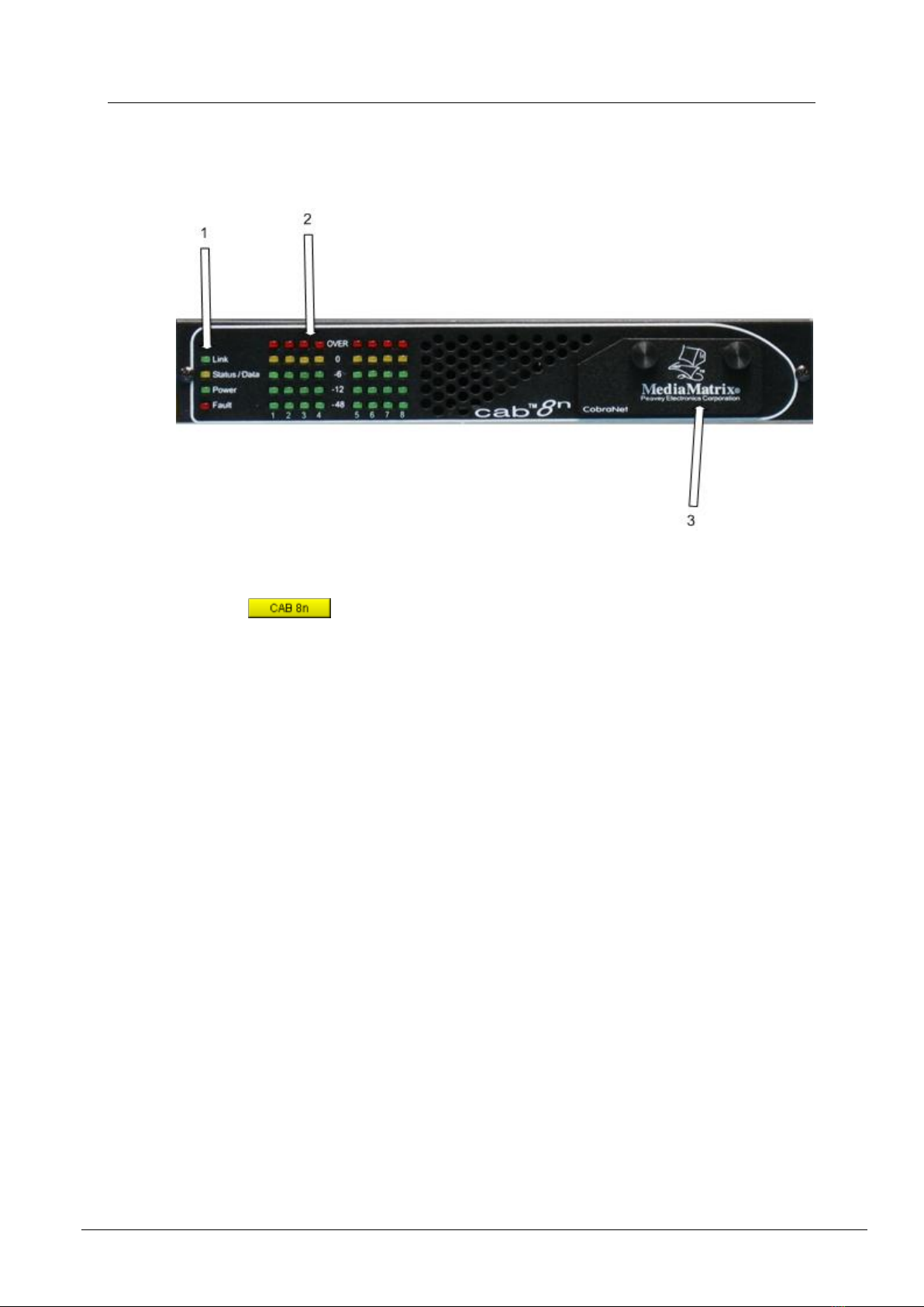
Front Panel
1. Status LEDs.
Link indicates that the physical layer connection has been established between the CAB
8n and the network switch. The status of the connection is also indicated by the Link LED
in the block in NWare.
Status/Data indicates that data is being transmitted or received from the CobraNet
network.
Power indicates that the CAB 8n is powered from an AC mains or PoE power source.
Fault indicates that a fault has occurred with the CAB 8n and the device has switched
to fault mode.
2. AUDIO METERS.
Peak reading LED ladder displays, indicating audio input/output levels. For inputs, the
signal level is displayed after the A/D converters. For outputs, the signal level is displayed
after the D/A converters.
3. REMOVABLE PANEL. Behind the panel are four rotary switches for setting the
hardware ID.

CAB 8n Hardware Manual
July 23, 2014 Version 1.7.1.0 11
.
Rear panel
1. AUDIO INPUT/OUTPUT CONNECTORS Eight channels of balanced analog audio,
independently selectable to be either mic/line input with phantom power, or line output.
These are identical to the NION audio connectors.
Note: If PoE is used, the total power consumed by the unit must not exceed 12.5W. If
more power is consumed, the unit will automatically shut down.
2. GPIO PORTS. Eight ports, independently configurable as digital out, high current digital
out, digital in or analog in at 10 bit resolution.
3. SERIAL PORT. Supports full duplex RS-232/EIA-485/EIA-422 serial communications
or half duplex EIA-485 serial communications. For information on the pin outs, see Serial
communications (on page 28).
4. CONTACT CLOSURES Ground pin (G), two user-controlled contact closure circuits
(R1 and R2), one fault indicator contact closure (RF) and one DC supply output connector.
The RF contact closure is activated when there is a fault with the CAB 8n and the Fault
LED on the front of the unit is lit.
Caution: If the Ext Pwr connector is used, the voltage available via the DC supply output
connector (marked DC Out) will be the same as the voltage supplied via the Ext Pwr
connector. Equipment connected to the DC Out connector must be compatible with the
supplied voltage.
Note: The DC Out connector cannot be used when the CAB 8n is powered using PoE.
5. FAULT CONNECTOR Three pin connector for linking the unit to a backup unit in a
fault tolerant configuration.
6. POWER CABLE RECEPTACLE Two-pin Mini Euro connector. Accepts 12-24V DC
at 1.6A.

Chapter 3 - Introduction to the CAB 8n
12 Version 1.7.1.0 July 23, 2014
Use only the supplied power supply with appropriate mains cable.
7. COBRANET NETWORK I/O Single RJ-45 connector provides interface to the
CobraNet audio network. This connector can also supply power to the unit if it is
connected to a Power over Ethernet (PoE) switch.

July 23, 2014 Version 1.7.1.0 13
In This Chapter
Introduction.......................................................................................................14
What you will need...........................................................................................16
Connections.......................................................................................................16
Setting the Hardware ID ...................................................................................24
Understanding gain structure............................................................................25
What to do next.................................................................................................25
Chapter 4
Installing the CAB 8n

Chapter 4 - Installing the CAB 8n
14 Version 1.7.1.0 July 23, 2014
.
Introduction
The CAB 8n is a 1RU device that can be mounted in a number of configurations:
In a 19" EIA equipment rack tray with one unit in the tray.
In a 19" EIA equipment rack tray with two units in the tray.
On a surface
Under a surface. The CAB 8n has four holes that pass right through the case (indicated by
the circles below), which are designed to allow it to be fixed under a surface by #8 or M4
screws.
This product should be installed so that its mounting position does not interfere with
proper ventilation. Do not block air intake or exhaust vents.

CAB 8n Hardware Manual
July 23, 2014 Version 1.7.1.0 15
The power switch in this unit does not break both sides of the primary mains.
Hazardous energy can be present inside the chassis when the power switch is in the
off position. The mains plug or appliance coupler is used as the disconnect device,
the disconnect device shall remain readily operable.

Chapter 4 - Installing the CAB 8n
16 Version 1.7.1.0 July 23, 2014
.
What you will need
A MediaMatrix NION with CobraNet interface.
The latest NWare software. (Updates can be downloaded from the MediaMatrix website
(http://mm.peavey.com/downloads/index.cfm).)
A computer running Microsoft Windows, with monitor, mouse and keyboard.
An assortment of CAT 5e or CAT 6 cables.
At least 1 CAB 8n.
An audio source, cables, power amplifier and loudspeaker.
A small Phillips screwdriver.
A small flat-blade screwdriver.
A network switch connected to the CobraNet network.
Note: The selection of a proper network switch is critical for a successful implementation.
Although CobraNet is an Ethernet protocol, there are performance issues that must be
considered when selecting this switch for use in CobraNet audio systems.
In MediaMatrix,the minimumCAB 8n CobraNet system consists of a single NION, a CAB 8n
and a single Ethernet switch. Many systems will include more NIONs and CAB devices, but
this is the most basic configuration.
Connections
CobraNet network connection
The first priority is the CobraNet™ network connection. The RJ-45 connectors on the
CobraNet interface are designed to connect with standard, off-the-shelf Category 5, 5e or 6
cable for use with standard Ethernet network switches.
Notes:
The network must be properly designed for each system. If you lack experience in
networking, we suggest that you partner with someone with networking experience.
Gigabit switches are recommended.
CAT 5e or CAT6 cables are recommended.
A typical CobraNet system includes a connection from each CAB to a network switch. An
additional network cable connects the switch to one or more NION CM-1 cards.
Note: The example below is the most basic configuration. Large systems on managed
networks can get very complex. We recommend that you get this configuration working
before attempting a more complex one.
Table of contents
Other MediaMatrix Media Converter manuals


 user guide")


