3
Effective 1 2020 Drawing No. LP1125
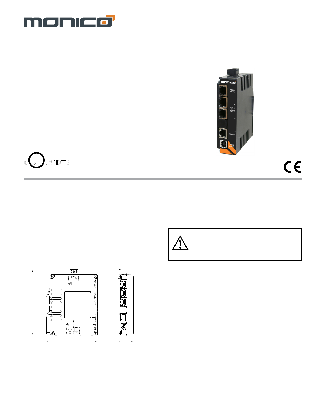
CONNECTING POWER
The PC10 requires a 24 VDC ±20%
power supply. A pluggable power block is
provided to connect the 24 VDC. There
are three screw terminals. Strip and
connect the wire according to the terminal
block specifications on Page 2. Connect
the positive lead to the plus (+) screw and
the negative lead to the minus (-) screw.
Please take care to observe the following points:
– Mount the power supply close to the unit, with usually not more than
6 feet (1.8 m) of cable between the supply and the operator
interface. Ideally, the shortest length possible should be used.
– The wire used to connect the operator interface’s power supply
should be at least 22-gage wire suitably rated for the temperatures
of the environment to which it is being installed. If a longer cable run
is used, a heavier gage wire should be used. The routing of the cable
should be kept away from large contactors, inverters, and other
devices which may generate significant electrical noise.
– A power supply with an NEC Class 2 or Limited Power Source (LPS)
and SELV rating is to be used. This type of power supply provides
isolation to accessible circuits from hazardous voltage levels
generated by a mains power supply due to single faults. SELV is an
acronym for “safety extra-low voltage.” Safety extra-low voltage
circuits shall exhibit voltages safe to touch both under normal
operating conditions and after a single fault, such as a breakdown of
a layer of basic insulation or after the failure of a single component
has occurred. A suitable disconnect device shall be provided by the
end user.
CONNECTING TO EARTH GROUND
The third pin of the power connector is chassis ground for the unit.
Your unit should be connected to earth ground. Steps should be taken
beyond connecting to earth ground to eliminate the buildup ofelectrostatic
charges.
The chassis ground is not connected to signal common of the unit.
Maintaining isolation between earth ground and signal common is not
required to operate your unit. But, other equipment connected to this unit
may require isolation between signal common and earth ground. To
maintain isolation between signal common and earth ground care must be
taken when connections are made to the unit. For example, a power
supply with isolation between its signal common and earth ground must
be used. Also, plugging in a USB cable may connect signal common and
earth ground.1
1USB’s shield may be connected to earth ground at the host. USB’s
shield in turn may also be connected to signal common.
EMC INSTALLATION GUIDELINES
Although Monico products are designed with a high degree of
immunity to Electromagnetic Interference (EMI), proper installation and
wiring methods must be followed to ensure compatibility in each
application. The type of the electrical noise, source or coupling method
into a unit may be different for various installations. Cable length, routing,
and shield termination are very important and can mean the difference
between a successful or troublesome installation. Listed are some EMI
guidelines for a successful installation in an industrial environment.
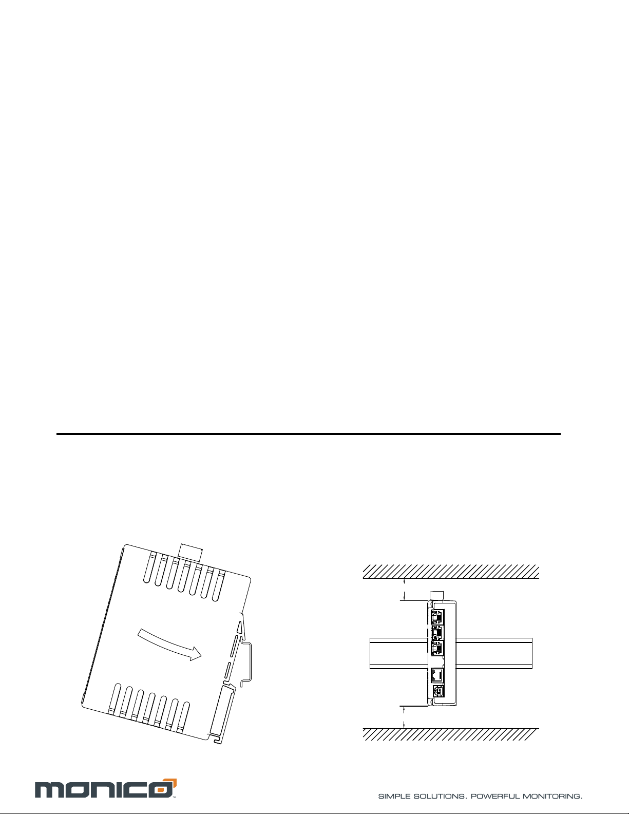
1. A unit should be mounted in a metal enclosure, which is properly
connected to protective earth.
2. Use shielded cables for all Signal and Control inputs. The shield
connection should be made as short as possible. The connection point
for the shield depends somewhat upon the application. Listed below
are the recommended methods of connecting the shield, in order of
their effectiveness.
a. Connect the shield to earth ground (protective earth) at one end
where the unit is mounted.
b. Connect the shield to earth ground at both ends of the cable, usually
when the noise source frequency is over 1 MHz.
3. Never run Signal or Control cables in the same conduit or raceway with
AC power lines, conductors, feeding motors, solenoids, SCR controls,
and heaters, etc. The cables should be run through metal conduit that
is properly grounded. This is especially useful in applications where
cable runs are long and portable two-way radios are used in close
proximity or if the installation is near a commercial radio transmitter.
Also, Signal or Control cables within an enclosure should be routed as
far away as possible from contactors, control relays, transformers, and
other noisy components.
4. Long cable runs are more susceptible to EMI pickup than short cable
runs.
5. In extremely high EMI environments, the use of external EMI
suppression devices such as Ferrite Suppression Cores for signal and
control cables is effective. The following EMI suppression devices (or
equivalent) are recommended:
Fair-Rite part number 0443167251
Line Filters for input power cables:
Schaffner # FN2010-1/07
6. To protect relay contacts that control inductive loads and to minimize
radiated and conducted noise (EMI), some type of contact protection
network is normally installed across the load, the contacts or both. The
most effective location is across the load.
a. Using a snubber, which is a resistor-capacitor (RC) network or metal
oxide varistor (MOV) across an AC inductive load is very effective at
reducing EMI and increasing relay contact life.
b. If a DC inductive load (such as a DC relay coil) is controlled by a
transistor switch, care must be taken not to exceed the breakdown
voltage of the transistor when the load is switched. One of the most
effective ways is to place a diode across the inductive load. However
external diode protection at the load is always a good design practice
to limit EMI. Although the use of a snubber or varistor could be used.
7. Care should be taken when connecting input and output devices to the
instrument. When a separate input and output common is provided,
they should not be mixed. Therefore a sensor common should NOT be
connected to an output common. This would cause EMI on the
sensitive input common, which could affect the instrument’s operation.