MediaQ MQ-1132 User manual

MQ-1132 / NEC 4121 Evaluation Board Users Guide MediaQ Incorporated
Board Revision 2
Revision A 4/12/01 Preliminary
1
MQ-1132 / NEC Evaluation Board Users Guide
Board Revision 2

MQ-1132 / NEC 4121 Evaluation Board Users Guide MediaQ Incorporated
Board Revision 2
Revision A 4/12/01 Preliminary
2
Introduction....................................................................................................................................................3
MQ-1132 Overview .......................................................................................................................................3
Platform Description......................................................................................................................................3
MQ-1132 Board Layout.............................................................................................................................4
Connectors..................................................................................................................................................4
Switches/Potentiometers/Miscellaneous ....................................................................................................4
Jumpers.......................................................................................................................................................5
Platform setup instructions.............................................................................................................................5
Hardware Assembly...................................................................................................................................5
Software Download....................................................................................................................................6
Flat Panel Interface.....................................................................................................................................6
Touch Screen / MMC .................................................................................................................................7
USB............................................................................................................................................................8
Audio ..........................................................................................................................................................8
Power..........................................................................................................................................................8
Related Documentation..................................................................................................................................8
MQ-1132 / NEC 4121 Evaluation Board Users Guide MediaQ Incorporated
Board Revision 2
Revision A 4/12/01 Preliminary
3
INTRODUCTION
This guide is intended to give a brief overview of the MQ-1132 and describe the features and workings of
the MQ-1132 / NEC 4121 Evaluation Board. This includes how to locate connectors, configure switches,
configure jumpers and the configuration of this evaluation board with the NEC VR4121 Development
Platform.
MQ-1132 OVERVIEW
The MQ-1132 is an integrated liquid-crystal display (LCD) and I/O controller with embedded memory for
low cost portable devices requiring long battery life and high performance. The MQ-1132 supports a
wide range of microprocessor interfaces including the NEC VR4121 Microprocessor. It has a high
bandwidth, 64-bit wide memory bus to embedded SRAM capable of bandwidths up to 192MB/S. The
MQ-1132 also integrates a high performance 2D graphics engine, LCD display interface, USB device and
host, Serial Peripheral Interface (SPI), I2S Audio Codec interface along with general purpose I/O and
LED pins.
PLATFORM DESCRIPTION
The MQ-1132 / NEC 4121 Evaluation Board along with the NEC VR4121 Microprocessor Development
Platform can be used to exercise the various features provided by the MQ-1132 as well as provide a
development and verification platform for hardware and software.
MQ-1132 / NEC 4121 Evaluation Board Users Guide MediaQ Incorporated
Board Revision 2
Revision A 4/12/01 Preliminary
4
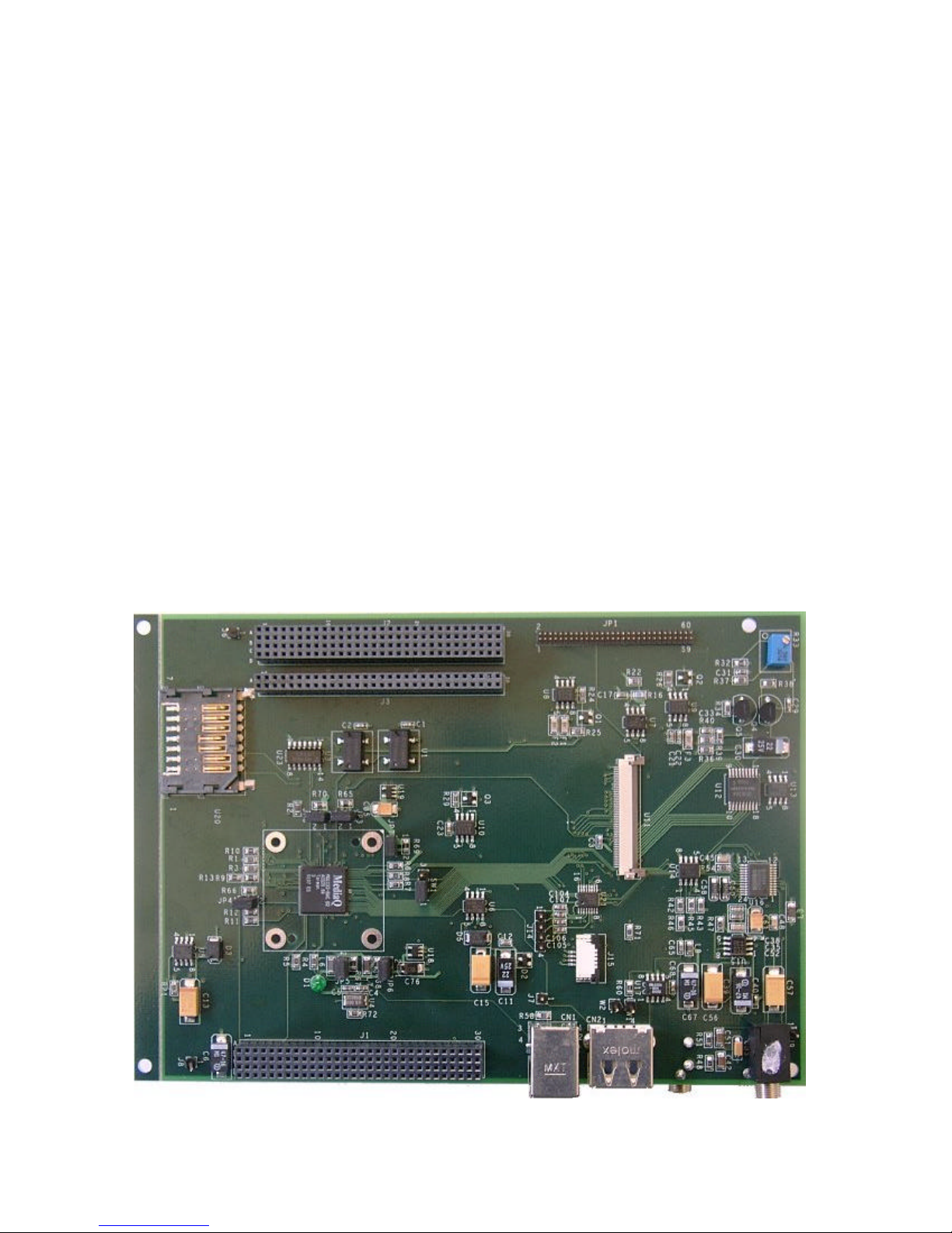
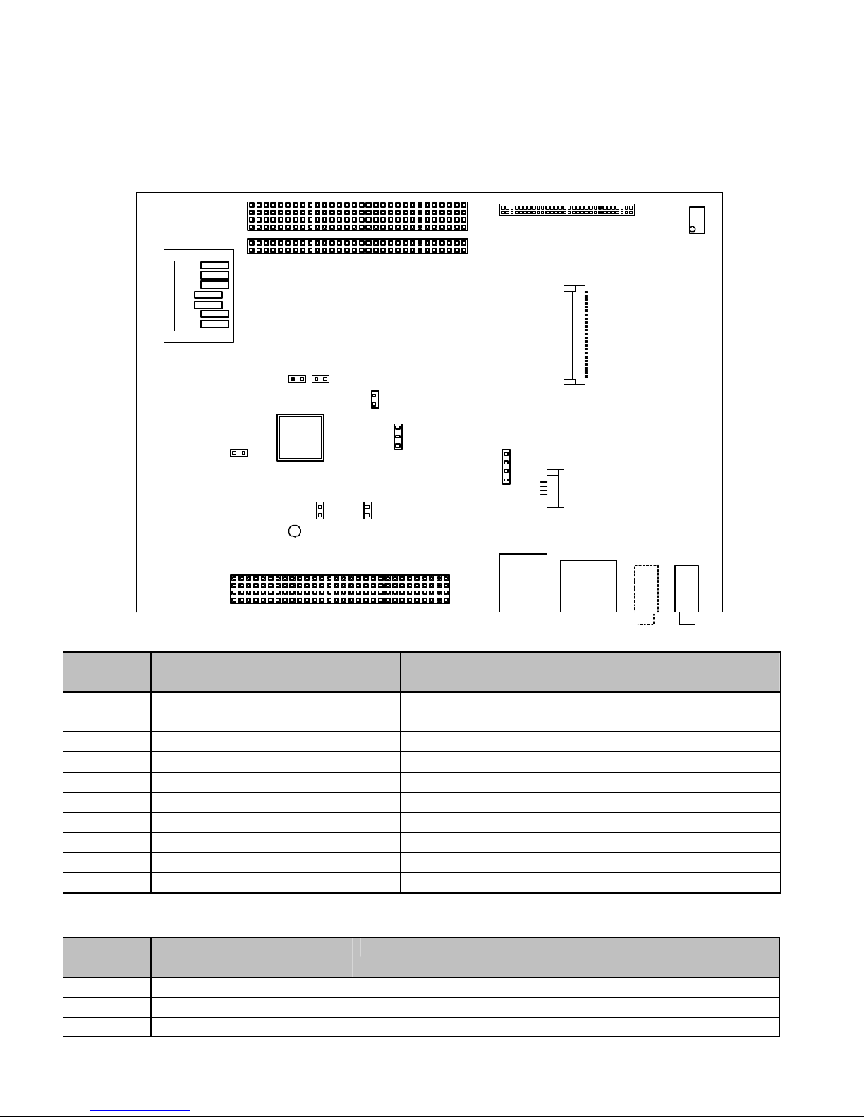
MQ-1132 Board Layout
The locations of the connectors, jumpers, switches and adjustable potentiometers are shown on the layout
diagram below. These are described in the tables on the following pages.
Connectors
Reference
Type Description
J1, J2, J3 4x30 (2) & 2x30 (1), 2mm long
tail female connectors NEC Falcon connectors
U11 50-pin flex cable socket Sharp HR TFT connector
JP1 60-pin, 50 mil, 2x30, male header Generic flat panel connector
J4/J5 Phone jack Audio input/output connectors
CN1-1 USB type B USB type B device connector
CN2-1 USB type A USB type A host connector
J14 4-pin, 1x4, 0.1” header Touchscreen connector
J15 4-pin flex cable socket Touchscreen connector for sharp HR TFT
U20 MMC Multi Media Card socket/connector
Switches/Potentiometers/Miscellaneous
Reference
Type Description
SW1 3-pin, 1x3, 0.1” header Powerdown (1-2 normal, 2-3 powerdown CPU I/F)
R33 Potentiometer (50K)
D1 LED Used to test GPIO 54 functionality
USB
HOST
SharpHRTFT s
MQ-
1132
USB
DEV
U11
JP1
J4 J5
AUDIO
IN
AUDIO
OUT
CN1-1 CN2-1
J14
J15
U20
MMC
J2
J1
J3 R33
SW1
JP7
JP3JP8
JP6
JP5
JP4 11
1
1
D1
MQ-1132 / NEC 4121 Evaluation Board Users Guide MediaQ Incorporated
Board Revision 2
Revision A 4/12/01 Preliminary
5
Jumpers
Reference
Type Description
JP3, JP4
JP5, JP6,
JP7, JP8
2-pin, 1x2,
0.1” header Power measurement jumpers for FVDD (flat panel), BVDD (Bus),
USBVDD (USB), AVDDOSC (Oscillator I/O ESD), CVDD24 (Core) and
CVDD13 (SRAM). Normal operation requires either these jumpers or
resistors R65, R66, R675, R686, R69 and R70 installed. Both jumper and
associated resistor removed when measuring power.
PLATFORM SETUP INSTRUCTIONS
The MQ-1132 / NEC 4121 Evaluation Board is used in conjunction with the NEC VR4121 Development
Platform. The following components are required and should be included in the NEC VR4121
Development package:
§NEC Falcon motherboard + VR4121 CPU module
§Parallel Cable (installed in J6 which will be under the MQ-1132 evaluation board when installed)
§Keyboard & PS/2 mouse
§ATX power supply
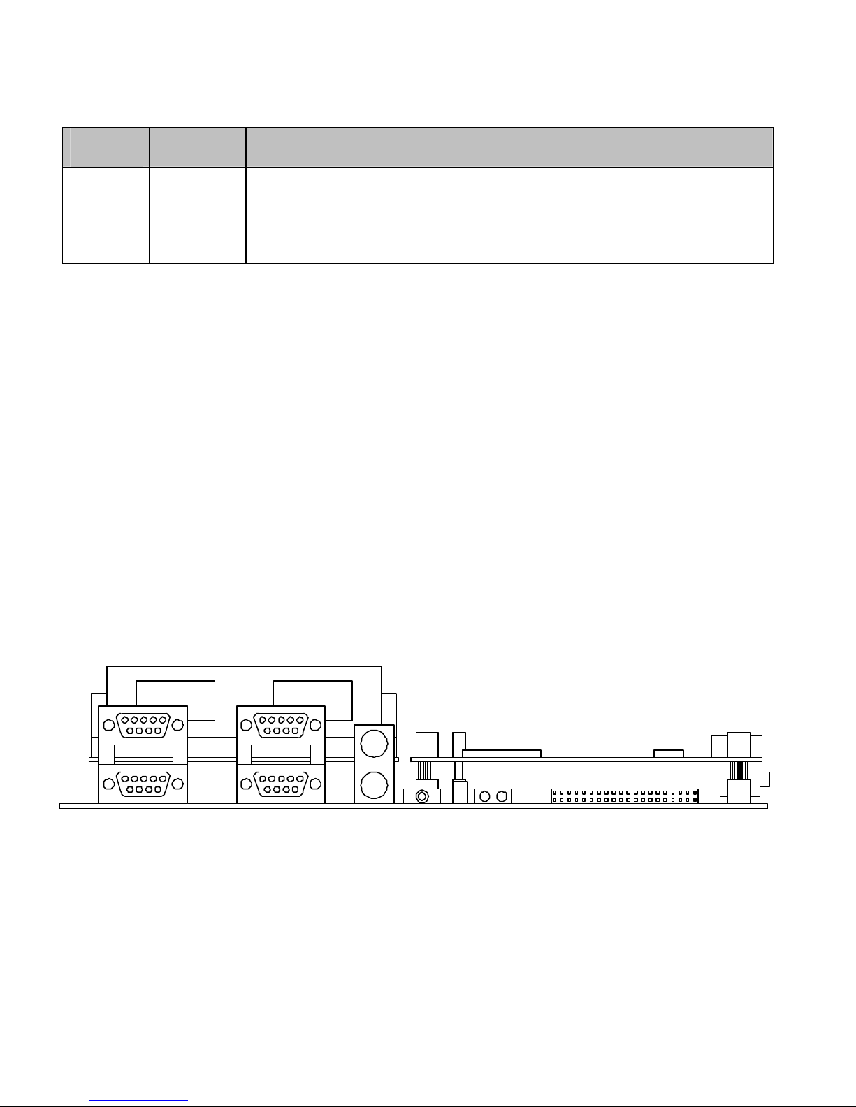
Hardware Assembly
The NEC VR4121 Development Platform has three connectors, J22, J80 and J36. These interface to the
MQ-1132 evaluation board. The final assembly should resemble the diagram below which is a side view
of the NEC VR4121 Platform including the NEC 4121 CPU module and MQ-1132 Evaluation Board.
Great care should be taken to ensure correct alignment of the sockets and pins to prevent damage during
assembly. When removing either the MQ1132 board or NEC CPU module, great care should be taken to
ensure that even pressure is asserted on both sides of the board to prevent bending of the pins.
Power is supplied to the NEC VR4121 Development Platform by way of an ATX power supply. Power
for the MQ-1132 board is supplied from the NEC VR4121 Platform bus connectors.
NEC Falcon Motherboard
NEC 4121 CPU Board
MQ-1132 Evaluation Board

MQ-1132 / NEC 4121 Evaluation Board Users Guide MediaQ Incorporated
Board Revision 2
Revision A 4/12/01 Preliminary
6
Software Download
To download the image, follow the instructions below (also included in NEC Development Platform
documentation):
1. Use straight 25-conductor male to male parallel cable to connect host parallel port to Falcon
parallel port ribbon cable (the host PC parallel port must support and be configured for EPP mode)
2. Launch the build environment
3. Depending on the version ofEboot either type “L” in Hyperterminal to issue the command to the
target board that you want to download an image file to Flash or this will be done automatically.
In either case, the system should respond with “Ready to download binary file from parallel
port” and the LED displays should read “LL”.
4. Set DIP Switch S1 #1 on the Falcon motherboard to On
5. Type “cesh –s nk.bin (or replace nk.bin with the name of the image file to be downloaded)
6. A status bar should appear at the lower left corner of the host’s Build Environment screen
indicating the percentage of the image downloaded to Flash
7. Set S1 #1 to Off and reset the motherboard to boot up with the new image
FUNCTIONAL DESCRIPTION
Flat Panel Interface
The MQ-1132 / NEC 4121 Evaluation Board has two connectors intended for interfacing to a variety of
flat panel displays. Connector U12 is used to interface directly to a Sharp HR TFT display
(LQ039Q2DS54). The MQ-1132 evaluation board has all the necessary power and power sequencing
circuitry necessary for this panel. Following are directions to connect the flat panel cable to the
evaluation board:
§Lift the brown lever on the HR TFT socket (U12)
§Insert the flat cable with the exposed portion facing up over the lever and under the top of the
socket
§Push down the brown lever –this should lock the cable into place and make electrical connection
Also provided, is a Generic Flat Panel connector (JP1) that can be used to interface the evaluation board
to panels other than the Sharp HR TFT. Custom cables are required to map the panel signals onto the
proper MQ-1132 pins. The cable requires a matching female connector to mate with the 60-pin, 50-mil,
2x30 male connector on the evaluation board. The part number for the female connector is M50-
3003022. Power is can be supplied by this connector for most panels. The pin assignment for the generic
connector are shown below:
MQ-1132 / NEC 4121 Evaluation Board Users Guide MediaQ Incorporated
Board Revision 2
Revision A 4/12/01 Preliminary
7
Pin
Signal Signal Pin
Pin
Signal Signal Pin
1 GND FVSYNC 2 31 R5 GND 32
3 R0 GND 4 33 GND G4 34
5 GND B5 6 35 G0 GND 36
7 R1 GND 8 37 FMOD LP 38
9 GND B4 10 39 G1 GND 40
11 R2 GND 12 41 GND DESPL 42
13 GND B3 14 43 G2 GND 44
15 R3 GND 16 45 GND ENVEE 46
17 GND B2 18 47 G3 3.3V* 48
19 SCLK GND 20 49 GND 3.3V* 50
21 GND B1 22 51 5V* GND 52
23 PWM1 GND 24 53 -11_7V* GND 54
25 PWMCON0 B0 26 55 -15V* GND 56
27 R4 GND 28 57 +15V* GND 58
29 FLCLK G5 30 59 FP_MODE NC 60
* From HR TFT Power Sequencing circuitry
The evaluation board also provides an adjustable voltage level (pin 25) to be used for contrast adjustment
on this Generic connector.
Touch Screen / MMC
The evaluation board supports two functions on the SPI interface. Only one device is selected at a time
by software setting two GPIO pins that control a multiplexer on the board. One of the functions is a touch
screen controller and the other is a Multi-Media Card (MMC) socket.
For the touch screen, two connectors are provided on the board to interface with various devices. J24
mates with the flat cable connected to the touch panel provided with the Sharp HR TFT display
(LQ039Q2DS54). To install the cable, pull out the sliding black portion of the socket, insert the cable
bare metal side up and then push the black portion back in locking the cable in place.
The other connector (J23) is a 1x4 0.1” standard header that can be used to interface to other touch
screens. A custom cable is required to connect a touch screen to J23. The pin out of this connector is
shown below (note, this touchscreen controller only supports standard 4-wire resistive touchscreens:
Pin Signal
1 X-Plus
2 Y-Minus
3 X-Minus
4 Y-Plus

MQ-1132 / NEC 4121 Evaluation Board Users Guide MediaQ Incorporated
Board Revision 2
Revision A 4/12/01 Preliminary
8
USB
Two USB connectors are provided on the evaluation board. CN2-1 is a Type A USB connector and
provides the USB Host functionality of the MQ-1132. CN1-1 is a Type Bconnector and provides the
USB Device function. Since the MQ-1132 USB device is a high speed device, CN1-1 is configured as
such.
Audio
The evaluation board supports audio input and playback/output. Audio input can come from any
amplified audio source and uses the Phone Jack J12. If a microphone is used it must be an amplified
version. Amplified audio output to headphones, amplified speakers or other destination is available on
the other Phone Jack at J13.
Power
Power is provided by the NEC VR4121 Development Board connectors and is regulated on the MQ-1132
Evaluation board. Headers (JP3 –JP8) can be installed (if missing) to allow power measurements of the
various blocks of the MQ-1132. Zero ohm resistors in parallel with these headers may be installed by
default instead of or in addition to the headers and must be removed in order to allow power
measurements.
RELATED DOCUMENTATION
•MQ-1132 / NEC 4121 Evaluation Board Schematics
•MQ-1100/1132 LCD and Peripheral Controller Datasheet
•Software release notes
Table of contents
Other MediaQ Motherboard manuals


Popular Motherboard manuals by other brands


Hitachi
Hitachi Network Adapter H8 user manual

Biostar
Biostar H77MU3 manual

ASROCK
ASROCK 939NF6G-VSTA installation guide

Analog Devices
Analog Devices Linear DC2543B Demo Manual

Linear Technology
Linear Technology DC2483A-A Demo Manual

Mellanox Technologies
Mellanox Technologies ConnectX-4 MCX4MHEVB-ECAA user manual