MedKlinn O3 Jetspray User manual

O3 Jetspray
USER MANUAL

1. Safety Precautions
2. Device Identication
3. System Overview
4. Getting Started
5. Basic Maintenance
1
3
9
12
19
TABLE OF CONTENT

1. Do not use the device if the power cable or plug is damaged.
2. Do not insert any sharp or pointed object through the ventilation holes of the device.
3. Do not let unauthorized personnel to play with the device.
4. Do not immerse the device in water, or allow water or any uids to enter through the ventilation holes.
5. When removing the power plug, always hold the plug and never pull the cable.
6. Do not remove the power plug when your hands are wet.
7. Remove the power plug from the wall socket before cleaning the device.
8. Do not modify, disassemble or repair this device without proper training unless stated in the manual.
9. Do not replace the electric plug or cut the power cable. Replacing the plug or cutting the power cable in any way will
immediately cause the Warranty to become void. Any subsequent fault in the operation of the device will not be covered by
the Warranty, and repair and servicing will be chargeable.
10. If the power cable is damaged, contact an authorized Medklinn Service Centre for repairs immediately.
11. Do not attempt to open the inner compartment of the device. The device requires minimal maintenance, and no servicing
or repairs are to be carried out by the User. Opening the device or tampering with it in any way will cause the Warranty to
become void. If you encounter any problems with the device, please contact the nearest authorized Medklinn Service Centre.
12. Do not wipe the device with benzene or paint thinner.
FOR FURTHER ASSISTANCE, PLEASE CALL OUR CUSTOMER SERVICE.
SAFETY PRECAUTIONS
WARNINGS - To reduce the risk of electrical shock, re or injury:
1.

NOTE – Radio, TV or sensitive equipment interference:
If the device should cause interference to radio, television reception or any sensitive equipment, try to correct the interference
by one or more of the following measures:
- Reorient or relocate the receiving antenna.
- Increase the distance between the device and radio/TV receiver/sensitive equipment.
- Connect the device into an outlet on a circuit dierent from that to which the receiver is connected.
- Consult the dealer or an experienced radio/TV technician for help.
Cautions during operation:
1. Place the device at least 6 feet from radio, television or electronic equipment. This is to minimize the possibility of
interference with the equipment or the remote controller.
2. Do not cover the device in any way at all, particularly the ventilation holes. Doing so will cause excessive heat build-up and
may result in a re and irreparable damage to the device.
3. Avoid placing the device where curtains or other furnishings may cover the ventilation holes.
4. Avoid placing the device in an oily environment as it may cause the module to be coated with a thicker layer of
grease/debris. Hence, aecting its performance.
5. Ensure that there is free ow of air around the device.
6. Avoid locations where the device is exposed to condensation due to rapid and drastic temperature uctuations. The device
should only be used in temperatures between 5º-35ºC.
2.
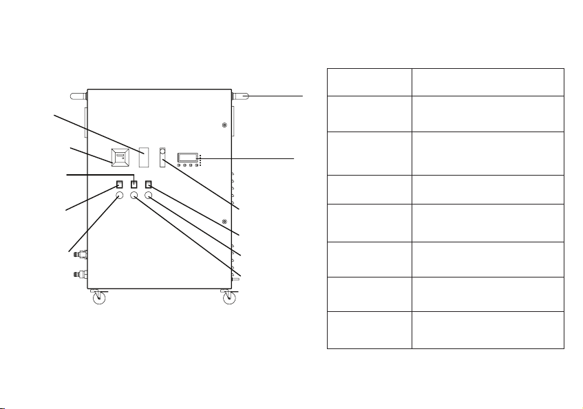
Device Identication
Side handle
Control panel
O2 control
Jetspray button
Jetspray indicator
Ozone water
indicator
Service
indicator
Ozone
water button
ON/OFF
button
Filter
Functional parts
Filter
Service indicator
O2 control
Filters the air supply
Indicates time to service the
device
Controls the amount of oxygen
owing into the device’s ozone
module
ON/OFF button To switch the device ON/OFF
Ozone water
button
To switch the ozone module
ON/OFF
Jetspray button To switch the jet spray mode
ON/OFF
Control panel
Side handle
Control/Monitors the entire
system
To ease moving and
positioning the device
ON/OFF
indicator
3.
Medklinn O3 Jetspray (Front View)
Table of contents


