Medrad Spectris Solaris EP User manual


North America Headquarters
MEDRAD Service Department
One Medrad Drive
Indianola, PA 15051-0780
U.S.A.
Tel: 412-767-2400
Fax: 412-767-4120
Nihon MEDRAD KK
2-4-9, Umeda, Kita-ku,
Osaka, 530-0001
Japan
Tel: +81(0)66-133-6250
Fax:+81(0)66-344-2395
European Headquarters
MEDRAD Europe B.V.
P.O. Box 205
6190 AE Beek
The Netherlands
Tel: +31 (0) 43-3585600
Fax:+31 (0) 43-3656598
© 2009-2012 MEDRAD, INC. All rights reserved.
Reproduction of this manual is strictly prohibited without express written
consent of MEDRAD, INC.
For more information about MEDRAD products and services, please visit
www.medrad.com


i
TABLE OF CONTENTS
1 - Introduction......................................................................................................1-3
Important Safety Notice ...................................................................................................... 1-3
Certifications ....................................................................................................................... 1-3
Indications for Use .............................................................................................................. 1-3
Contraindications ................................................................................................................ 1-3
Restricted Sale.................................................................................................................... 1-3
Required Training ...............................................................................................................1-3
Trademarks......................................................................................................................... 1-3
Disclaimers ......................................................................................................................... 1-3
The Equipotential Connector (EPC).................................................................................... 1-4
Understanding Symbols...................................................................................................... 1-4
Warnings............................................................................................................................. 1-6
Cautions.............................................................................................................................. 1-8
2 - System Basics .................................................................................................2-9
About the Injection System ................................................................................................. 2-9
Pressure Safety Limit........................................................................................................ 2-10
Response to Occlusions ................................................................................................... 2-10
Volume and Rate Protection ............................................................................................. 2-10
Control Room Unit ............................................................................................................ 2-11
Scan Room Unit................................................................................................................ 2-12
Injector Head..................................................................................................................... 2-13
Battery Charger.................................................................................................................2-14
Optional Control Room Unit Accessories.......................................................................... 2-15
Touch Screen Calibration ................................................................................................. 2-16
Help Mode......................................................................................................................... 2-16
Setup Mode....................................................................................................................... 2-17
3 - Preparing to Inject .........................................................................................3-19
Applying Power ................................................................................................................. 3-19
Main Screen...................................................................................................................... 3-20
Battery Maintenance ......................................................................................................... 3-21
Syringe and Disposable Accessory Installation ................................................................ 3-22
Retracting the Pistons................................................................................................ 3-22
Installing a Syringe .................................................................................................... 3-23
Loading a Syringe...................................................................................................... 3-25
Reinstalling a Syringe ................................................................................................ 3-27
Programming .................................................................................................................... 3-28
Flow Rate and Volume .............................................................................................. 3-28
Pressure Limit............................................................................................................ 3-28
Multiple Phases ......................................................................................................... 3-29
Hold and Pause Phases ............................................................................................ 3-29
Programmed Delay.................................................................................................... 3-30
Scan Delay ......................................................................................................... 3-30
Inject Delay ......................................................................................................... 3-30
Stopwatch ........................................................................................................... 3-31
KVO (Keep Vein Open) ............................................................................................. 3-31

MEDRAD Spectris Solaris EP MR Injection System
ii
Storing a Protocol .............................................................................................................3-33
Recalling a Stored Protocol .............................................................................................. 3-34
4 - Arming and Injecting.....................................................................................4-35
Arming............................................................................................................................... 4-35
Single and Multi-Arm......................................................................................................... 4-35
Insufficient Volume............................................................................................................ 4-36
Injecting............................................................................................................................. 4-36
Disarming.......................................................................................................................... 4-37
Injection History ................................................................................................................ 4-39
Clean Up ........................................................................................................................... 4-40
Appendix A: System Messages........................................................................ A-43
Type 1 Messages..............................................................................................................A-43
Type 2 Messages..............................................................................................................A-44
Type 3 Messages..............................................................................................................A-44
Appendix B: Maintenance and Checkout ....................................................... B-45
Recommended Maintenance Schedule ............................................................................B-45
Inspection Procedures ......................................................................................................B-46
Cleaning Guidelines..........................................................................................................B-48
Operational Checkout .......................................................................................................B-48
Appendix C: Specifications .............................................................................. C-51
Scan Room Unit............................................................................................................... C-51
Control Room Unit ........................................................................................................... C-52
Battery Dimensions.......................................................................................................... C-52
Battery Charger................................................................................................................ C-53
Power Cords .................................................................................................................... C-53
System Capabilities ......................................................................................................... C-54
Executable Flow Rates .................................................................................................... C-54
System Performance ....................................................................................................... C-55
Forward and Reverse Controls........................................................................................ C-55
EMI/RFI............................................................................................................................ C-56
Electrical Requirements ................................................................................................... C-56
Power Supply DC Output Voltage.................................................................................... C-56
Electrical Leakage............................................................................................................ C-56
Ground Continuity ............................................................................................................ C-56
Environmental Specifications........................................................................................... C-56
Classifications .................................................................................................................. C-57
Appendix D: Options and Accessories............................................................ D-59
Appendix E: System Installation ...................................................................... E-61
Unpacking the Injection System........................................................................................E-62
Installation Considerations................................................................................................E-63
Fiber Optic Cable Installation............................................................................................E-65
Control Room Unit Setup..................................................................................................E-66
Handswitch Mounting........................................................................................................E-67

1 - Introduction
1 - 3
1 - Introduction
This manual applies to the MEDRAD Spectris Solaris®EP MR Injection
System, Catalog Number 3012011. Read all of the information contained in
this section. Understanding the information will assist you in operating the
device in a safe manner.
Important Safety
Notice
This device is intended to be used by medical professionals with adequate
training and experience in magnetic resonance imaging (MRI) studies.
Certifications This device is equipped to operate at 100-240 VAC, 50/60 Hz, 180 VA
(Single), and is designed to comply with EN 60601-1/IEC 60601-1 Second/
Third Edition, and EN 60601-1-2 Second Edition and IEC 60601-1-2 Second/
Third Edition Standards.
Indications for Use This system is intended for the purposes of injecting intravenous MR contrast
media and common flushing solutions into the human vascular system for
diagnostic studies in magnetic resonance imaging (MRI) procedures.
Contraindications This device is not to be used in the arterial side of the vascular system, for
drug infusion, chemotherapy, or any other use for which the device is not
indicated. The system should not be used with a magnetic resonance imaging
scanner having a magnetic field strength greater than 3.0 Tesla.
Restricted Sale Federal (USA) law restricts this device to sale by or on the order of a
physician.
Required Training This device is intended to be used by individuals with adequate training and
experience in diagnostic image studies.
Trademarks MEDRAD, FluiDot, Qwik-Fit, Spectris Solaris, MEDRAD Radiology,
Performance for Life are federally registered trademarks of MEDRAD, INC.
The trademarks Becton Dickinson, Daiichi, NSKK, Multihance, Gadovist,
Magnevist, Optimark, Prohance, and Omniscan appear in this manual, and
are the property of their respective companies.
Disclaimers External wiring and modifications disclaimers: MEDRAD disclaims liability for
any modifications or interfaces with other equipment which are not in
conformity with the specifications and information contained within this
manual.
Accessory equipment connected to the device must be certified according to
IEC 60601-1 Second/Third Edition standard. Furthermore, all configurations
shall comply with system standard EN 60601-1/IEC 60601-1-1. Anyone who
connects additional equipment to the signal input or output part configures a
medical system and is therefore responsible that the system complies with the
requirements of the standard IEC 60601-1-1. To obtain on-site consulting or
consulting references, contact MEDRAD Service.
The MEDRAD Spectris Solaris EP MR Injection System is not intended for
portable use.
MEDRAD Spectris Solaris EP MR Injection System
1 - 4
The Equipotential
Connector (EPC)
The Equipotential Connector (EPC) is an electrically bonded terminal on the
injector that is used as a connection point between other medical electrical
equipment. The EPC’s function is to minimize any voltage potentials
differences between all connected equipment. The EPC is not designed to be
an electrical safety ground.
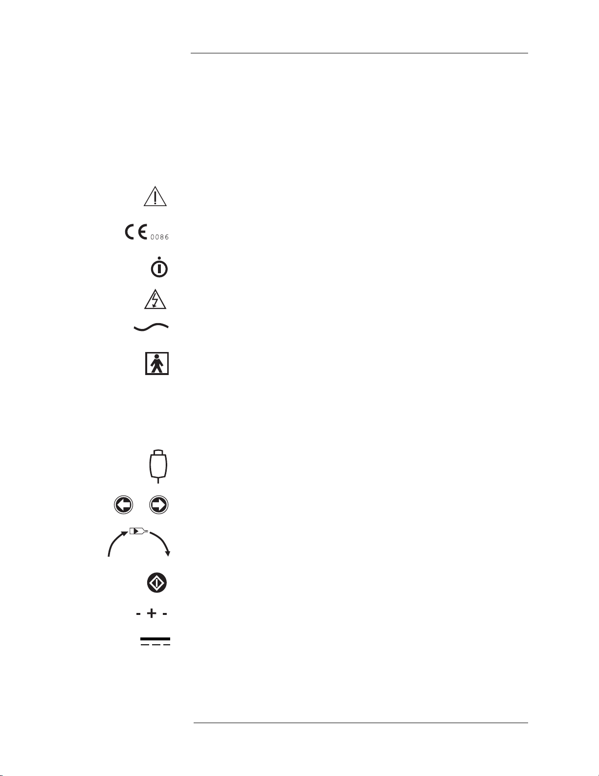
Understanding
Symbols
The following symbols are used on the MEDRAD Spectris Solaris EP Mobile
MR Injection System and components.:
Attention, consult accompanying instructions.
Indicates that this device conforms to the requirements of the European
Medical Device Directive 93/42/EEC.
Indicates on/off switch for the Control Room Unit.
Indicates hazardous voltages.
Indicates alternating current.
Identifies a type BF applied part complying with EN 60601-1 standards.
CLASS 1 Indicates the injection system is Class 1 medical equipment as defined by
EN 60601-1 standards.
IPX1 Identifies the degree of protection against fluid as drip proof for the
Spectris Solaris EP Injector system.
Identifies connection of the handswitch.
Identifies injector head forward and reverse piston control keys.
Identifies the direction of manual knob rotation relative to plunger
movement.
Identifies the ENABLE key.
Identifies polarity of the battery pack terminals.
Indicates DC power supply.

1 - Introduction
1 - 5
Indicates the current charge level of the system battery.
Identifies Integrated Continuous Battery Charger system activity on
Graphical User Interface. When illuminated yellow this indicates that the
Continuous Battery Charger system is present and functioning.
Indicates the AIR EXPELLED button on the injector head. When
illuminated yellow on the touch screen, also indicates that the operator has
acknowledged inspecting the fluid path for air.
Identifies the Equipotential connection.
Identifies the Earth Ground point.
IOIO Identifies the Service Connection Port.
Identifies the Locking Bracket. Indicates which direction to turn Locking
Bracket knob to “lock” and “unlock” the bracket.
TX Identifies the Communication Cable Transmit connection.
RX Identifies the Communication Cable Receive connection.
Indicates design for indoor use only.
Identifies the Integrated Continuous Battery Charger System power supply
connection.
Indicates the presence of no serviceable parts.
IIndicates the presence of AC power at the battery charger.
Identifies the Control Room Unit brightness controls.
P109 Reserved for future use.
Indicates the status of the battery charger. When a battery is properly
inserted, the LED will illuminate while charging, and extinguish when the
battery is fully charged.
Pushing Prohibited. Do not push at or above this point on the Injector.

MEDRAD Spectris Solaris EP MR Injection System
1 - 6
This manual contains important information about use of the MEDRAD
Spectris Solaris EP MR Injection System.
MEDRAD urges you to read this manual carefully, become familiar with the
procedures and system functions that it describes, and follow its
recommendations to assure proper use of the system.
Labels on the system or statements in this manual preceeded by any of the
following words and/or symbols are of special significance, intended to help
you to operate the system in a safe and successful manner:
WARNING: Indicates that the information is a warning. Warnings
advise you of circumstances that could result in injury or death to the
patient or operator. Read and understand the warnings before
operating the injection system.
CAUTION: Indicates that the information is a caution. Cautions advise
you of circumstances that could result in damage to the device. Read
and understand the cautions before operating the injection system.
Note: Indicates that the information that follows is additional
important information or a tip that will help you recover
from an error or point you to related information within the
manual.
Warnings Patient injury may result from a system malfunction. If a system
malfunction occurs, immediately remove unit power (by pulling the battery
from the Scan Room Unit), and disconnect the unit from the patient. If a fault
message is displayed that cannot be corrected, and/or the system is not
operating correctly, do not use the injection system. Call MEDRAD for
assistance.
Patient injury could result from leaks or ruptures during an injection. To
prevent leaks or ruptures in the event of a blockage, use only catheters and
connectors with pressure ratings compatible with this system.
Explosion hazard. The MEDRAD Spectris Solaris EP MR Injection System is
not suitable for use in the presence of a flammable anesthetic mixture with air,
oxygen, or nitrous oxide.
Fire hazard. To avoid an electrical fire, assure the correct type of fuse is used
for replacement. The fuse must be replaced with Type F, 250 V, 2.5 A fuse by
qualified personnel only.
Electrical shock hazard. Hazardous voltages exist within system
components. Do not remove or open any enclosure.
Electrical shock hazard. Avoid fluid entry into system components. Do not
immerse any components in water or cleaning solutions. Use a damp cloth
when cleaning on or around the battery and the Integrated Continuous Battery
Charger system power supply.
Electrical shock hazard. Serious injury or death may result from exposure to
hazardous voltages existing within the system. Disconnect the Battery
Charging System from line power and remove the battery from the Scan
Room Unit before cleaning.

1 - Introduction
1 - 7
Electrical shock hazard. Equipment must only be connected to a supply
mains with protective earth.
Ventilation hazard. To avoid a build up of hydrogen gas from the battery,
assure the room is well ventilated while battery is charging.
Improper disposal of the battery pack may result in explosion, leakage,
or personal injury. Do not open, or dispose of in a fire! Follow all local
regulations concerning the disposal of spent lead-acid based batteries, or
contact MEDRAD for assistance.
System electronic assemblies contain potentially hazardous materials.
Dispose of system components or accessories properly. Follow local
regulations for proper disposal or contact MEDRAD Service for assistance.
Unsafe operation may result from using improper accessories. Use only
accessories and options provided by MEDRAD designed for this system.
Chemical burn hazard. Always carry the battery pack firmly by the battery
pack hand grips. Damage to the housing may result in a chemical burn
hazard. Do not use if the housing is severely cracked or damaged.
Voltage hazard from worn cabling or unit disassembly. To avoid exposure
to potentially hazardous voltages, do not disassemble the injection system in
any way. Worn cabling also creates voltage hazards. If any worn or damaged
cables are detected, do not use the injection system. Contact MEDRAD for
service or replacement.
The MEDRAD Spectris Solaris EP MR Injection System is a dual syringe
system. Always ensure that the proper syringes are loaded with contrast
media and flush solution prior to the injection. Failure to properly load and
install the syringes may require the procedure to be repeated. Syringe A is
designated for contrast agent use only. Syringe B is designated for flush
solutions only.
Injury or equipment damage may result from use of tools containing
ferrous materials. Use only non-magnetic tools to install any scanner/
magnet room components.
Patient injury and/or catheter damage may result from using connector
tubing (LPCT) that is too short. Operator must consider tubing length and
stretch limitations when moving the injector or the patient.
Serious injury or death may result from syringe failure. Do not retract
pistons with connector tubing installed. Retracting the pistons with the
connector tubing installed on syringes will create a vacuum in the syringe due
to the check valve in the connector tubing. This vacuum may accelerate the
plunger rapidly toward the tip of the syringe when it is removed from the
injector causing the syringe to break.

MEDRAD Spectris Solaris EP MR Injection System
1 - 8
Cautions Condensation may cause electrical damage to the injection system. Do
not use the system immediately after it has been brought indoors from
extreme outside temperatures. Allow the system to stabilize at room
temperature before use.
Injector may disarm or fail to operate upon exposure to high
electromagnetic fields that may be generated by radio transmitters or cellular
phones, or upon exposure to high levels of electrostatic discharge.
This injector system is in compliance to IEC-60601-1-2 / Second and
Third Edition Standards. Special precautions regarding ElectroMagnetic
Compatibility (EMC), are required for installation and use of this injector
system. Detailed EMC information can be found in the MEDRAD Injector
Service Manual - Addendum, (label number: 202559).
Damage can occur as a result of incorrect voltage. Before plugging in the
system, check the following:
• Verify that the voltage and frequency marked on the serial tag on
the back of the unit matches the voltage and frequency of the
electrical outlet.
• Verify that the Control Room Unit and the Battery Charger power
supply have the appropriate power cord plugs for the power
outlet.
Additional warnings, cautions, and notes are located throughout this manual,
where applicable.
2 - System Basics
2 - 9
2 - System Basics
About the Injection
System
The MEDRAD Spectris Solaris EP MR Injection System is a programmable,
dual syringe system, designed to accurately administer controlled doses of
intra-venous MR contrast agents and common flushing solutions to patients
undergoing a contrast enhanced MR scan.
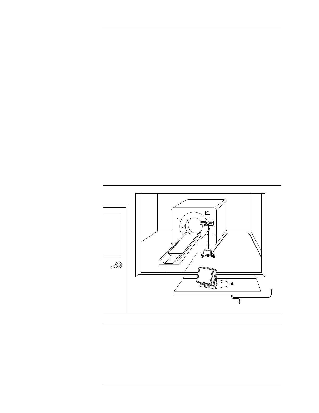
The system consists of two basic components that communicate by a direct
connection of fiber optic lines.
• The Control Room Unit houses the Touch Screen and electronic
components used to program the injection system.
• The Scan Room Unit, positioned near the magnet bore, contains
the Injector Head, system battery pack, and the mechanical
assemblies required for fluid delivery.
A battery charger is also supplied with the system, used to charge the Scan
Room Unit battery pack. For convenience, the charger can be used in the
control room, but should never be installed or operated in the scan room.
Note: Follow all institutional, local, or national safety regulations
related to routing cabling on the floor.

MEDRAD Spectris Solaris EP MR Injection System
2 - 10
Pressure Safety
Limit
The MEDRAD Spectris Solaris EP MR Injection System is designed to allow
varied flow rates for contrast injections. By automatically reducing the flow
rate, the system can limit the pressure produced during an injection to prevent
damage or failure of any connecting devices or tubing. This feature is called
Pressure Safety Limit.
Inability to maintain the desired flow rate while remaining below the Pressure
Safety Limit can be caused by various conditions including contrast viscosity,
catheter sizing, connector tube sizing, and stopcock restrictions. If the system
is unable, for a period of three seconds, to maintain a flow rate of at least 10%
of the programmed rate, the system will disarm due to a stall condition.
If unable to automatically achieve the required level of flow rate reduction,
thus reaching the Pressure Safety Limit, the system will terminate the
injection and move to a disarm state.
Response to
Occlusions
When injecting into an occlusion, a stall condition (flow rate less than 10% of
programmed rate) will result. A stall condition lasting more than 3 seconds (3
minutes for programmed rates less than 0.1 ml/sec) will result in the injection
being automatically terminated.
If an occlusion occurs during KVO (Keep Vein Open) the system will detect
the condition after 4 or less KVO boluses fail to be delivered. This will
correspond to from 1 minute with a KVO interval of 15 seconds configured, to
5 minutes with a KVO interval of 75 seconds. Refer to the Setup screen to
determine the current KVO setting.
If a stall occurs due to an occlusion, and the blockage is subsequently
removed, less than 10 ml will be delivered as the pressure in the
administration set dissipates.
Volume and Rate
Protection
The following means are provided to protect against over and under volume
or rate conditions:
• Warnings displayed on the Safety screen and during the arming
sequence remind the operator to check the programmed injection
parameters prior to the system being armed.
• An onscreen indication of insufficient volume is provided whenever the
total volume programmed to be delivered is greater than the amount of
fluid in the syringe.
• Injection monitoring is performed to detect over rate or over volume
conditions due to system faults. If either of these conditions is detected,
the injection will be stopped before an additional 10 ml of fluid above
programmed volume is delivered.
2 - System Basics
2 - 11
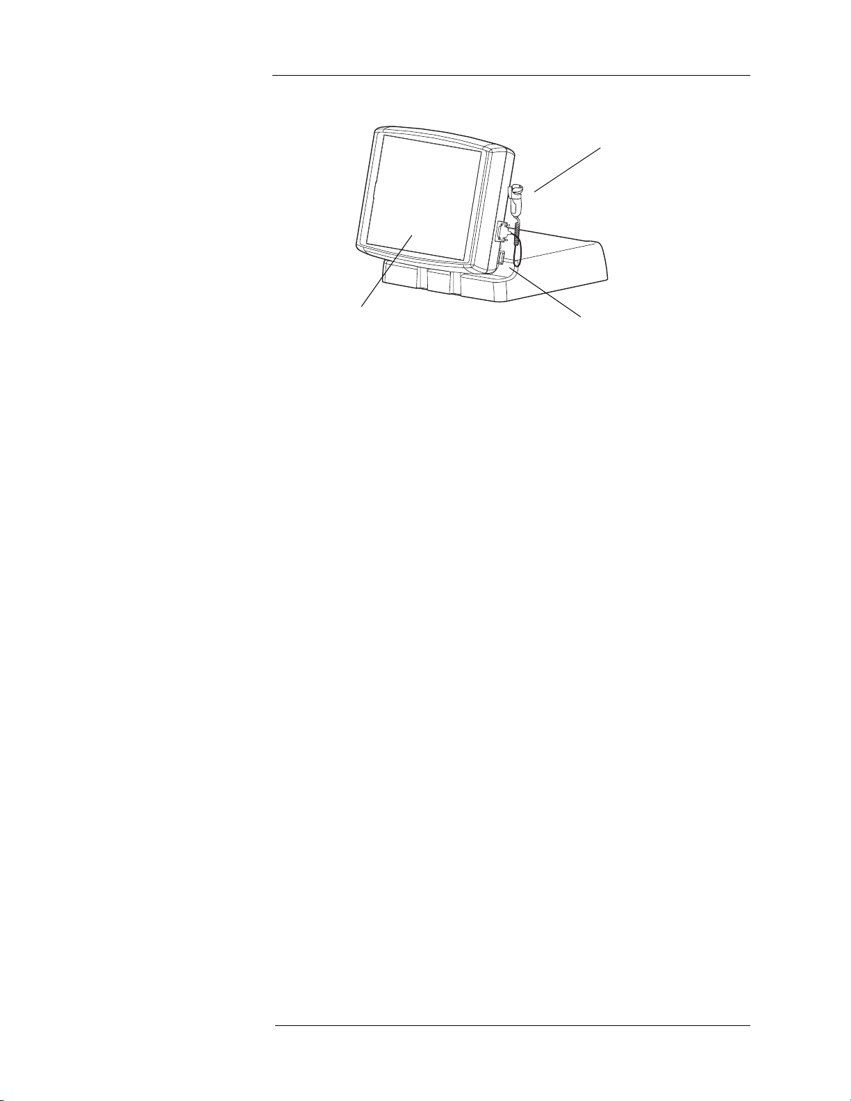
Control Room Unit
1. Handswitch
2. System Power Switch
3. Touch Screen
At rear of Touch Screen Assembly - Display Contrast Controls
1
32

MEDRAD Spectris Solaris EP MR Injection System
2 - 12
Scan Room Unit
1. Injector Head
2. Handswitch
3. Lower Console
4. System Battery Pack
5. Middle Pivot Clamp
Not shown - Contrast Holder (optional)
1
3
4
2
5
2 - System Basics
2 - 13
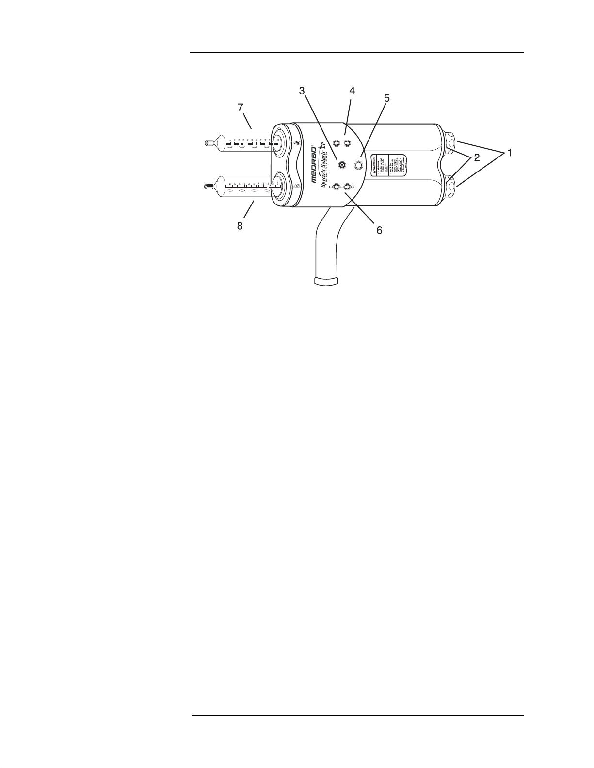
Injector Head
1. Manual piston movement knobs
2. Armed indicator lights
3. ENABLE button - Used to activate the forward/reverse controls - the
appropriate direction must be selected within 5 seconds.
4. Syringe A forward/reverse controls
5. AIR EXPELLED button/indicator
6. Syringe B forward/reverse controls
7. Syringe A: Contrast agent
8. Syringe B: Flush solution

MEDRAD Spectris Solaris EP MR Injection System
2 - 14
Battery Charger
1. Battery Pack
2. Battery Charging Unit
3. Charging Indicator - Amber
4. Power Indicator - Green
5. Battery Charger Head
1
3
4
5
2
2 - System Basics
2 - 15
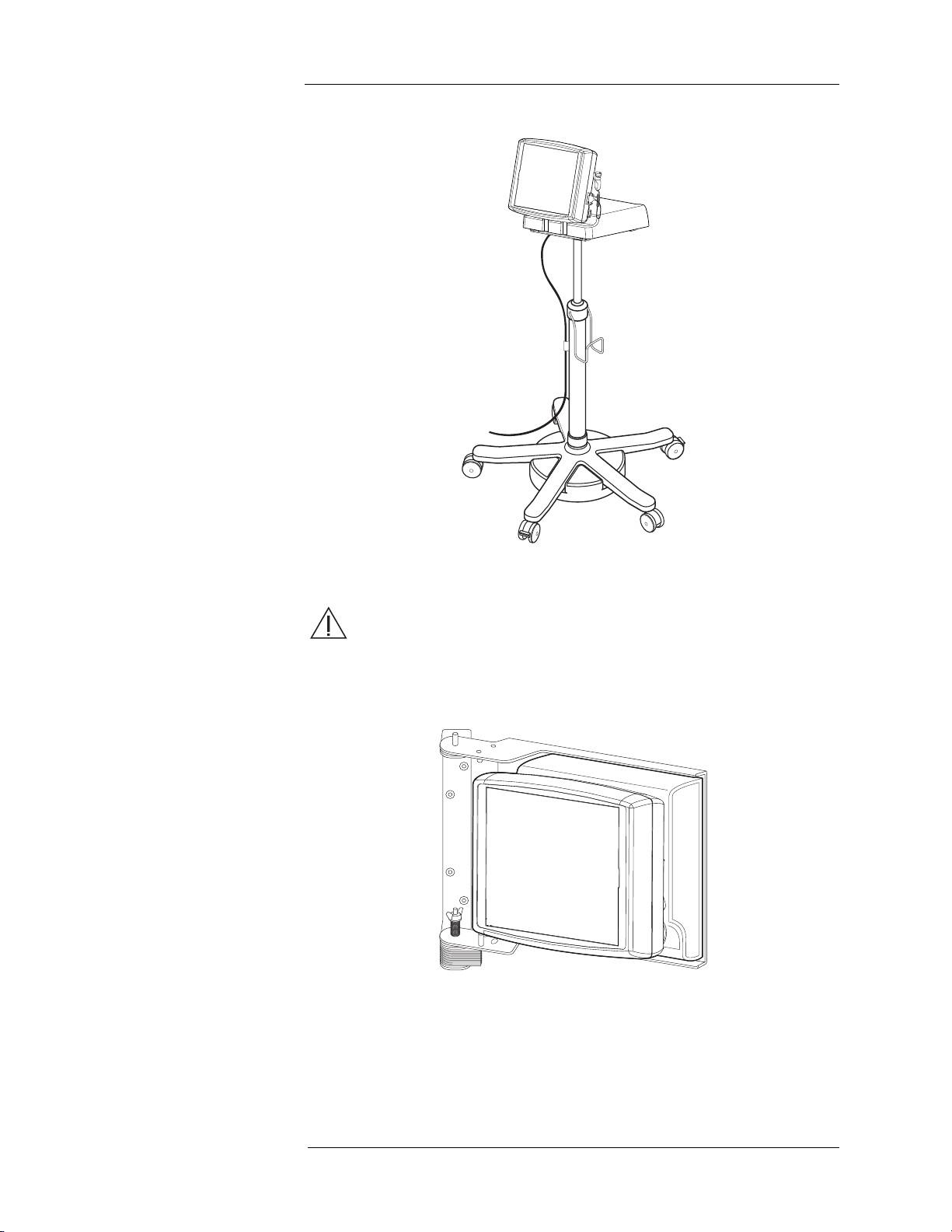
Optional Control
Room Unit
Accessories
Adjustable Height Pedestal
WARNING: Injury or equipment damage may result if the
adjustable height pedestal is taken into the scanner room. Do not
take the adjustable height pedestal in the scanner room. It
contains ferrous material that could be attracted toward the magnet.
Wall Mounting Bracket
Note: These accessories contain ferrous material and are
designed to be used in the Control Room only. Do not
install or operate in the Scan Room.

MEDRAD Spectris Solaris EP MR Injection System
2 - 16
Touch Screen
Calibration
To enter Touch Screen Calibration mode, simultaneously press both the
Contrast UP and DOWN keys on the rear of the touch screen housing. A
series of screens with instructions to press the appropriate calibration circles
will appear.
CAUTION: Do not touch the screen with a sharp object in order to
perform the calibration.
Help Mode The Help screen can be accessed by pressing the HELP button on the lower
right corner of the Main screen. Besides safety information, the Help screen
displays a variety of topics as displayed below.
Other manuals for Spectris Solaris EP
1
Table of contents
Other Medrad Medical Equipment manuals

Medrad
Medrad Avanta User manual

Medrad
Medrad AngioJet Ultra User manual

Medrad
Medrad Intego User manual

Medrad
Medrad MRXPERION User manual

Medrad
Medrad Mark 7 Arterion User manual

Medrad
Medrad Spectris Solaris EP User manual

Medrad
Medrad ProVis Mark V User manual

Medrad
Medrad Mark 7 Arterion User manual

Medrad
Medrad Stellant D Instruction Manual


