Medrad ProVis Mark V User manual

Service Manual
KMP 870
98411-T-205 Rev. D


Table of Contents
TOC - 1
Table of Contents
2 - Preface
Copyright Notice 2 - 1
Trademarks 2 - 1
Patents 2 - 1
Restricted Sale Notice 2 - 1
Applicability 2 - 1
European Council Directive Compliance 2 - 1
Manual Purpose 2 - 1
Safety Notice 2 - 1
Disclaimers 2 - 2
Address/Telephone 2 - 2
Introduction to Warnings and Cautions 2 - 3
Statement of Intended Use 2 - 3
Contraindications 2 - 3
Warnings 2 - 3
Cautions 2 - 5
3 - Condensed Operating Guide
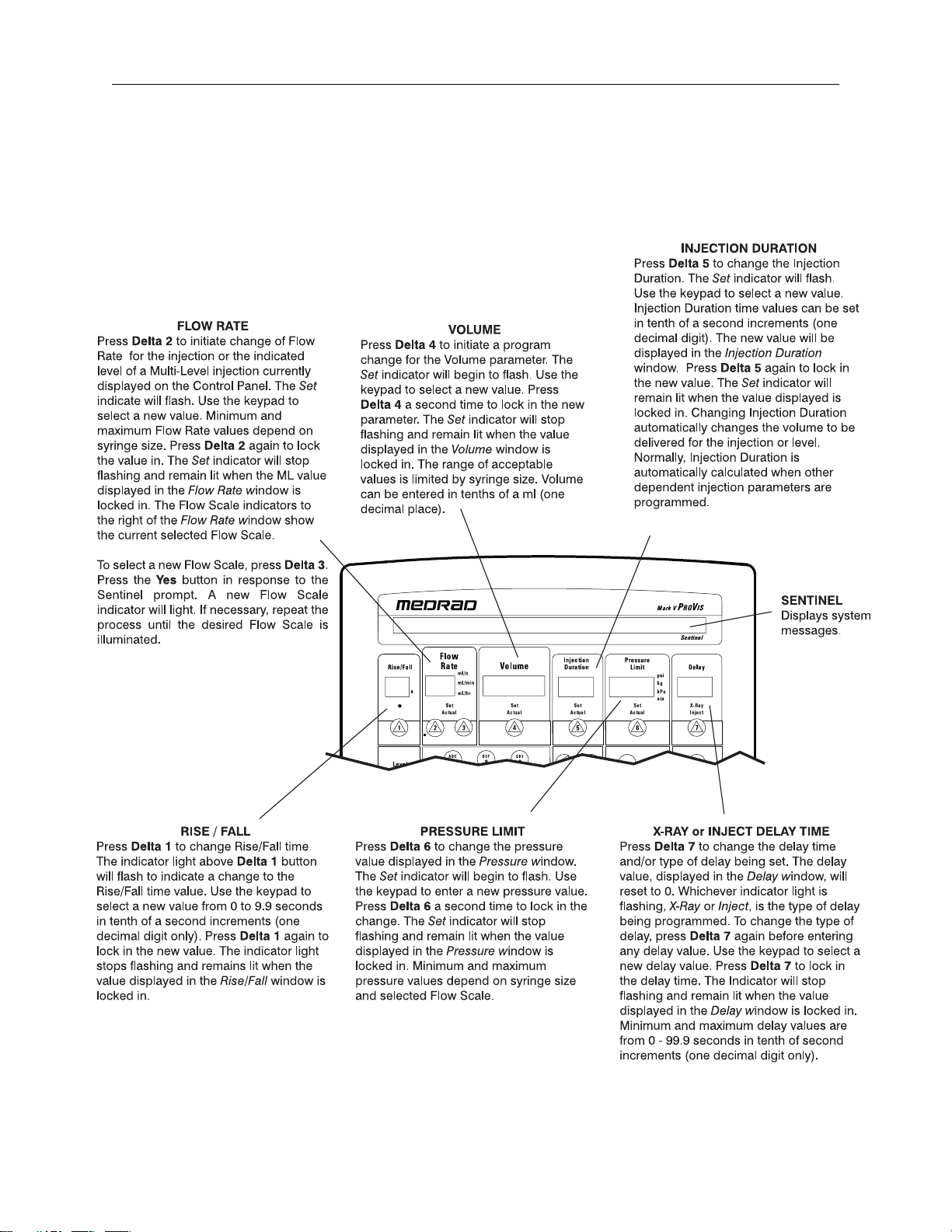
Control Panel 3 - 1
4 - Preventive Maintenance
Recommended Preventive Maintenance 4 - 1
Recommended Preventive Maintenance Schedule 4 - 2
Inspection Procedures 4 - 3
Cleaning Procedures 4 - 5
Leakage Check 4 - 6
Ground Continuity Check 4 - 6

Mark V ProVis Injection System
TOC - 2
5 - CPU Card
CPU Card - Summary of Operation 5 - 1
Block Diagram: CPU Card 5 - 2
6 - Input/Output Card
I/O Card - Summary of Operation 6 - 1
Block Diagram: I/O Card 6 - 2
7 - Servo Control Card
SCC Card - Summary of Operation 7 - 1
Block Diagram: SCC Card 7 - 4
8 - Pre-Programmed Injection Card
PPI Card - Summary of Operation 8 - 1
Block Diagram: PPI Card 8 - 2
9 - Control Panel
Control Panel - Summary of Operation 9 - 1
Controller Card 9 - 2
Block Diagram: Controller Card 9 - 4
DC to DC Converter 9 - 5
Block Diagram: DC to DC Converter 9 - 6
10 - Power Drive Circuit
Description of Power Drive Circuit 10 - 1
PDCI Card - Summary of Operation 10 - 2
Block Diagrams: Power Drive (PDCI) Circuit 10 - 8
11 - Mechanical Stop Drive
MSD Card - Summary of Operation 11 - 1
Block Diagram: MSD Card 11 - 2
12 - Power Supply Circuit
PSC - Summary of Operation 12 - 1
Block Diagram: PSC Card 12 - 2

Table of Contents
TOC - 3
13 - Injector Head
Description of Injector Head 13 - 1
Description of Motor and Drive System 13 - 2
Description of Feedback Pots 13 - 2
Description of Syringe Heat Maintainer 13 - 2
Circuit Descriptions:
Injector Head Card 13 - 2
SIP Switch Settings 13 - 6
Block Diagram: Head Card 13 - 7
14 - Imaging System Interface
Description of Imaging System Interface 14 - 1
Interfacing Cautions 14 - 2
Imaging System Interface Circuits 14 - 4
Block Diagram: Imaging System Interface 14 - 6
Z5 Option 14 - 7
Schematic: Siemens Interface 14 - 8
Schematic: Phillips Interface 14 - 9
15 - Troubleshooting Guide
Required Test Equipment 15 - 1
Service Access Card (SAC) 15 - 2
SAC Test Points 15 - 3
Troubleshooting Guide:
Introduction 15 - 6
General Troubleshooting Guidelines 15 - 7
Suggested Troubleshooting Sequence 15 - 9
Message Faults: 15 - 10
Non-Message Faults: 15 - 32
Dead Unit 15 - 33
No Drive 15 - 34
Will Not Inject 15 - 35
Garbled Message 15 - 35

Mark V ProVis Injection System
TOC - 4
16 - System Disassembly and Reassembly Procedures
Introduction 16 - 1
Replacement Parts 16 - 2
Replacement Circuitry 16 - 4
How to Order Parts 16 - 6
Required Tools 16 - 7
Control Unit
Electronics Console Access 16 - 8
PC Cards 16 - 9
Control Panel
Removal and Replacement 16 - 10
Display Card 16 - 11
Controller Card 16 - 12
Injector Head
Covers 16 - 13
Syringe Heat Maintainer 16 - 14
Plunger Position Pot 16 - 16
Mechanical Stop Pot 16 - 19
Plunger Motor Drive Belt 16 - 21
Plunger Drive Motor 16 - 23
Mechanical Stop Motor 16 - 25
Head Control Panel 16 - 27
Mechanical Stop Limit Switch 16 - 28
Injector Head Cable 16 - 29
Oil Seal 16 - 30
Pivot Knuckle Adjustment 16 - 31
Power Switch 16 - 32
Line Voltage Conversion 16 - 33
Line Frequency Conversion 16 - 35
Line Frequency Checkout 16 - 36

Introduction
2 - 1
2Introduction
Copyright Notice Copyright 2009 by MEDRAD, INC. All rights reserved. No part of this
manual may be reproduced in any form without prior written permis-
sion of MEDRAD. Printed and assembled in the U.S.A.
Trademarks FluiDot, MEDRAD, and Quality for Life, are registered trademarks of
MEDRAD Incorporated.
Patents The Mark V ProVis Injection System is the subject of the following U.S.
patent numbers: 4,677,980; 4,854,324; 5,383,858.
Restricted Sale Federal (U.S.A.) law restricts the sale of this device to, or by the order
of a physician.
Applicability This manual applies to Mark V ProVis Injection Systems in the follow-
ing configurations:
PPD 100 60 XXX PRM 100 60 XXX
PPD 110 60 XXX PRM 110 60 XXX
PPD 20050 XXX PRM 200 50 XXX
PPD 220 50/60 XXX PRM 220 50/60 XXX
PPD 240 50 XXX PRM 240 50 XXX
All Mark V ProVis models are designed to be in compliance with EN
60601-1 (Safety) and EN 60601-1-2 (EMC/Emissions).
Represents compliance to the European Council Directive
concerning medical devices - 94/42/EEC.
Purpose This manual is intended to provide instructions for servicing the Mark V
ProVis Injection System (herein referred to as “the injection system”
safely and accurately. It is intended for those qualified to service the
injection system, whether they be MEDRAD Service Personnel, Labo-
ratory Service Technicians, or MEDRAD Authorized Dealers.
Important
Safety Notice
The information in this manual is intended for people with adequate
backgrounds and experience in electronics and electromechanical
devices. Any attempt to repair a sophisticated medical device such as
the injector may result in personal injury, property damage, or patient
injury.

Mark V ProVis Injection System
2 - 2
Disclaimers MEDRAD makes no warranties on the contents of this manual, and specif-
ically disclaims any implied warranties of merchantability or fitness for any
purpose.
MEDRAD reserves the right to change specifications and the contents of
this manual without obligation.
MEDRAD reserves the right to modify the specifications and features
described herein, or discontinue manufacture of the product described at
any time, without prior notice or obligation. Please contact your authorized
MEDRAD representative for the most current information.
External Wiring and Modification: MEDRAD disclaims liability for any
modifications or interfaces with other equipment which are not in confor-
mity with the specifications and information contained within this manual.
Such unauthorized action could jeopardize injector operation, safety, or
reliability.
Accessory equipment connected to the system interfaces must be certified
according the IEC 601-1 standards. Furthermore, all configurations with
attached accessory equipment shall comply with the system standard IEC
601-1-1. Anyone who connects additional equipment to the signal input or
output configures a medical system, and is therefore responsible that the
system complies with the requirements of the system standard IEC 601-1-
1. To obtain on-site consulting or consulting references, contact MEDRAD
Factory Service.
All drawings in this manual are for reference purposes only, and may not
reflect the construction of units produced prior to the publication of this
manual. Reproduction quality of these drawings may have been affected
by the level of reduction required. Call MEDRAD Factory Service if assis-
tance in drawing interpretation is required.
The injection system is not intended for portable use.
Problems or
Questions
If you experience problems with any MEDRAD Injection System, contact:
MEDRAD Factory Service MEDRAD EUROPE, B.V.
MEDRAD, INC. Postbus 205
One MEDRAD Drive 6190 AE Beek
Indianola, PA 15051-0780 The Netherlands
Phone: (412) 767-2400 Phone:(31) (0) 43 3585601
1-800-MEDRAD-S FAX: (31) (0) 43 3656598
1-800-633-7237
FAX: (412) 767-4126
Nihon MEDRAD K.K.
2-4-9, Umeda, Kita-ku,
Osaka, 530-0001
Japan
Phone:+81(0)66-133-6250
FAX: +81(0)66-344-2395

Introduction
2 - 3
INTRODUCTION TO
WARNINGS / CAUTIONS
This manual contains important information about safe servicing of the
injection system.
MEDRAD urges the service technician to read this manual carefully,
become familiar with the procedures and system functions that it
describes, and follow its recommendations to assure proper servicing
of the system.
Warning labels on the injection system or Warning statements in this
manual preceeded by any of the following words and/or symbols are of
special significance:
WARNING: Indicates a potentially hazardous situation. If
not avoided, this could result in death or serious injury.
CAUTION: Indicates potential hazards or unsafe practices
which could cause product, system, or property damage.
NOTE: Indicates helpful information is being offered.
Intended Use This device is intended to be used specifically for the purpose of inject-
ing intravenous contrast medium into humans, for the purpose of diag-
nostic studies. DO NOT attempt to use the injector for any other
purpose.
Contraindications This device is not to be used for drug infusion, chemotherapy, or any
other use for which the device is not indicated.
!
!

Mark V ProVis Injection System
2 - 4
WARNINGS Dangerous voltages exist within the injection system that can shock,
burn, or cause death. To avoid injury, the system should be opened and
serviced by qualified service personnel only. Disconnect the system from
line power before cleaning or attempting to perform any maintenance or
repairs.
Mains Voltage Hazard. To avoid dangerous voltages, do not remove con-
nector J130 while power is applied to the system. Always disconnect the
system from line power before removing connector J130
Live Voltage Hazard. Avoid contact with J40 pins. Ensure that the connec-
tor cover is in place or cable is connected.
Possible explosion hazard in the presence of flammable anesthetic
gases. The injection system is not designed for use in association with
anesthetic gases and equipment.
Electronic assemblies contain potentially hazardous materials. Dis-
pose of system components or accessories properly. Follow all local regu-
lations for the recycling or disposal of electronic assemblies, or contact
MEDRAD Service for assistance.
Worn power cords or control cables may shock, injure, or cause
death. Examine power cords and cables for cuts, frays, or any other visible
damage. Do not use the system if any of the cords or cables show signs of
damage. Any damaged or worn connection cables or power cords should
be replaced.
Check for proper voltage and frequency before connecting the injec-
tor to an electrical outlet. Failure to do so may result in personal injury or
equipment damage/malfunction. Check the voltage and frequency marked
on the back of the unit. Ensure that the outlet providing power to the injector
supplies a voltage, frequency, and volt-ampere rating within the range
specified.
Do not use an extension cord or power cord adaptor. Connect the
injector directly into a properly grounded AC outlet. Since the power cord
supplies a safety ground to the unit, using an extension cord will compro-
mise ground quality and the injector could become unsafe.
Do not immerse any injector components in water or any type of
cleaning solution. Fluid entry may result in a shock hazard.
Ensure that FluiDot labels are clearly visible on all pressure jackets.
FluiDot labels are intended to help in the avoidance of air embolization,
which could result in patient injury or death.
Injury may result from springing action when injector head is
removed from the arm. Move the arm to the maximum upright position
before removing the injector head. When re-mounting the injector head,
ensure that the retention knob is secured to prevent the injector head from
falling from the arm.
!!

Introduction
2 - 5
Injury may result if excessive weight is applied to the device. Do not
place heavy objects or lean on the arm, injector head, or handles.
Injury may result during the transport of the injection system. Care
should be taken when transporting the injector. Ensure that the articulat-
ing arm is secured by inserting the locking pin.
Pinch Hazard. Do not grasp any pivot points. Position the injector head
by grasping the arm or extension.
CAUTIONS Electrostatic Discharge (ESD). Failure to follow ESD protection prac-
tices may result in equipment damage. To avoid damage, ESD protection
practices must be followed when servicing any component of this system.
If electronic components are to be shipped, place the components in con-
ductive carriers (as supplied at MEDRAD).
Disconnect the power cord before removing or replacing PC
boards. Sensitive circuits on the boards can be damaged by abrupt inter-
ruption or application of supplies.
Remove power when disconnecting or reconnecting head cables.
Disconnecting the head cable from the injector pedestal, or head exten-
sion cable from the rack or table mounts, when power is applied, may
result in equipment damage.
Allow system temperature to stabilize before use. When the system
is exposed to an extreme temperature change (heat or cold), allow it to
stabilize to room temperature before servicing.
Use only accessories and options designed specifically for the
Mark V ProVis injection system. To ensure compatibility and proper
operation, do not use an accessory or option designed for another sys-
tem.
Perform regular preventive maintenance. To ensure that your injection
system remains properly calibrated, and that all primary and backup cir-
cuits are functioning properly, regular preventive maintenance is recom-
mended. An annual preventive maintenance package (offered in the
U.S.A., Canada, and Europe) is available at an additional cost. Contact
your local MEDRAD Factory Service Representative for details.
Do not soak or immerse any part of the injection system in water.
Improper or careless cleaning methods may result in equipment damage.
While cleaning any outside portion of the system, avoid allowing any
water to seep inside system components.
Do not short the PPI Card Batteries. Do not place the card or the bat-
teries on any conductive surface. When checking or replacing the PPI
card batteries, discharge can occur with even a momentary short.
!!

Mark V ProVis Injection System
2 - 6
Do not apply voltage to ISI connector J40 pins 5,6,7,8 or 9. Equip-
ment damage or malfunction may result.
Do not move the injector or pedestal by pulling on the syringe
heater cable. Equipment damage or malfunction may result.Do not
connect injector head extension cables in parallel. Connecting the
extension cables in parallel, or extending the total extension length
beyond 100 feet (30.5 m), can adversely effect injector performance and
specifications.
NOTE: All relevant institutional, local, or national safety regula-
tions related to cable routing and installation should be
followed.
Do not apply voltage to external start lines if the injector is being
started by an external start connection. Provide only a switch closure.
If the external circuit contains excessive line frequency noise or voltage
transients, injector damage or malfunction may result.
The Remote Start Signal from the film changer programmer (at pins
7 and 9 of J40), must never contain voltage or AC noise. Any voltage
applied to these pins can damage the injector and void the warranty.
Excess noise on these lines may cause intermittent problems of prema-
ture, or no injections.
The Remote Start Signal from the film changer programmer must
remain closed throughout the duration of the injection. If the start
signal is removed before the injection volume limits when armed in the
SINGLE mode, the injection will stop, the unit will disarm, and display
“PREMATURE TERMINATION” on the Control Panel. If the start signal
is removed before the injection volume limits when armed in the MULTI-
ple mode, the injection will stop, the Mechanical Stop will reposition at
the selected volume, and the unit will remain armed. If a start signal is
received at this time, an additional injection will result at the selected
Flow Rate and Volume.
When starting the injection process from a remote location by the
use of a relay closure in the film changer programmer, always
install a “panic button” in series with the start signal. This function
must be provided in the event that the operator must immediately termi-
nate the injection. This button should be installed in a convenient loca-
tion, properly labeled, and instructions for use provided to all users of the
injection system.
Operating Guide
3 - 1
3Operating Guide

Mark V ProVis Injection System
3 - 2

Preventive Maintenance
4 - 1
Preventive
Maintenance
This section contains recommended procedures for preventive main-
tenance of injection systems. Routine maintenance and inspection
will:
• Ensure the continued performance of your injector.
• Reduce the possibility of equipment malfunction.
Recommended
Procedures
Preventive maintenance of the injection system should consist of four
procedures: Inspection, cleaning, leakage, and performance checks.
This section contains guidelines, recommended methods, and
expected results for each of these procedures:
1. Inspection: This first step should encompass inspection of the
entire system, looking for obvious signs of damage, such as;
cracks in the housing, frayed or worn cables, missing or damaged
labels, and contrast spills that may have leaked into the injector.
2. Cleaning: This cleaning procedure involves thorough cleaning of
the console and head to remove any deposits of contrast medium.
If any substances have leaked into any part of the unit, the subas-
sembly should be disassembled and thoroughly cleaned.
3. Electrical Leakage / Ground Continuity Checks: To ensure the
safety of the patient and hospital personnel in injector operations.
4. Operational Checkout: A complete functional performance check-
out of the injection system.
4

Mark ProVis Injection System
4 - 2
Recommended
Schedule
The injection system must be properly maintained to ensure that it is
in peak operating condition. Your individual maintenance schedule
depends upon how your injector is used; the type of procedures per-
formed, and frequency of use. The following guidelines represent a
suggested maintenance schedule:
Daily:
Before use each day, the system should be inspected, and the injector
head piston rod thoroughly cleaned.
Monthly:
Once a month, the entire system should be thoroughly inspected and
cleaned, and an operational checkout should be performed.
Annually:
Once per year, Electrical Leakage and Ground Continuity checks
should be performed.
NOTE: Local regulations or hospital protocol may require elec-
trical leakage checks at more frequent intervals. If this
applies, local regulations for leakage must be followed.
MEDRAD also recommends that a complete system calibration and
performance checkout, by a qualified MEDRAD Service Representa-
tive, be performed once a year. Contact MEDRAD Factory Service, or
your local MEDRAD office for details.
In the United States, Canada, Europe, and other select areas of the
world, the MEDRAD Service Department offers Preventive Mainte-
nance Programs. These annual programs greatly assist in maintaining
accuracy and reliability, and can extend the life of the injection system.
Contact MEDRAD for details. In Europe, contact MEDRAD Europe
B.V., or your local authorized dealer, for further information. Refer to
Section 2 of this manual for address and telephone numbers.
NOTE: Failures which occur due to lack of proper mainte-
nance, or abuse, will not be covered under warranty.

Preventive Maintenance
4 - 3
Inspection
Procedures
The following procedures are recommended for all the components of the
injection system. If defects are detected, either repair the system, or call
MEDRAD for service. Do not use the unit until the problem has been cor-
rected.
Injector Head 1. Inspect the housing for any cracks that could allow fluid to leak inside,
or weaken the structural integrity of the unit.
2. Inspect the head cable for cuts, cracks, or worn areas.
3. Inspect the head connector for cracks, loose pins, or a loose strain
relief.
4. Inspect the injector head control panel for cuts or cracks that could
allow fluid to leak inside.
Syringe Heat
Maintainer
1. Ensure that the device is warm to the touch.
2. Ensure that the LED indicator is not illuminated or flashing when
installed on the pressure jacket/syringe. The lamp may illuminate if the
syringe heat maintainer is not installed on the pressure jacket/syringe.
If the lamp is illuminated while installed on the pressure jacket/syringe,
the heater is too hot and should be replaced.
3. Inspect the cable and connector for cracks, worn areas, loose pins, or
a loose strain relief.
Control Panel 1. Inspect the control panel case for cracks that could allow fluid to leak
inside, or weaken the assembly.
2. Inspect the interconnect cable for cuts, cracks, or worn spots. Inspect
the plug for cracks, loose prongs, loose wires, or a loose strain relief.
3. Inspect the handswitch and cord: Look for cuts, cracks, or worn spots
in the cable; look for cracks and loose parts in the switch and housing.
4. Inspect any other cables connected to the control unit: Look for cuts,
cracks, or worn spots in the cables; look for cracks, loose pins, or
loose strain reliefs on the connectors.
Pedestal Mount 1. Inspect the case and legs for cracks and other defects that could
weaken the structure.
2. Ensure that all mounting bolts and screws are secure.
3. Inspect the connectors on the pedestal for cracks or loose pins.
4. Ensure that the wheels roll smoothly, with no binding and scraping.
5. Ensure that the locking mechanism on all locking wheels is functional.

Mark ProVis Injection System
4 - 4
Injector Head
Articulating Arm
The injector head support arm is typically associated with pedestal type
injection systems and free standing injector head stands. Carefully
inspect the areas shown below for any signs of damage.
1. Inspect all parts of the mounting system for cracks and other defects
that would weaken the assembly.
2. Ensure that the mounting system is securely assembled, with no
loose parts. The system should be stable with the head installed.
3. Ensure that the system moves smoothly in all directions, with no bind-
ing, scraping, or drifting.
4. Verify that all cabling is tied back and does not interfere with the
movement of the supporting parts or the injector head.
NOTE: The injector head pivot knuckle should rest flat and rotate
smoothly on the support arm.
NOTE: The head cable can wrap around the support arm, causing
damage to the head cable, and possibly lifting the injector
head from the support arm. Contact MEDRAD Factory
Service for support arm replacement information.
Counterpoise
Systems
1. Inspect all parts of the mounting system for cracks and other defects
that would weaken the assembly.
2. Ensure that the mounting system is securely assembled, with no
loose parts. The system should be stable with the head installed.
3. Ensure that the system moves smoothly in all directions, with no bind-
ing, scraping, or drifting.
4. Verify that all cabling is tied back and does not interfere with the
movement of the supporting parts or the injector head.
NOTE: All relevant guidelines for institutional, local, or national
safety recommendations related to cable routing and
installation should be followed.
NOTE: Rotating the counterpoise consistently in one direction can
cause the head extension cable to wrap around the coun-
terpoise, causing possible equipment damage.
NOTE: The head cable can wrap around the support arm, causing
damage to the head cable, and possibly lifting the injector
head from the support arm. Contact MEDRAD Factory
Service for support arm replacement information.
Table of contents
Other Medrad Medical Equipment manuals

Medrad
Medrad AngioJet Ultra User manual

Medrad
Medrad Intego User manual

Medrad
Medrad Spectris Solaris EP User manual

Medrad
Medrad Spectris Solaris EP User manual

Medrad
Medrad Avanta User manual

Medrad
Medrad MRXPERION User manual

Medrad
Medrad Stellant D Instruction Manual

Medrad
Medrad Mark 7 Arterion User manual

Medrad
Medrad Mark 7 Arterion User manual
Popular Medical Equipment manuals by other brands


Getinge
Getinge Arjohuntleigh Nimbus 3 Professional Instructions for use

Mettler Electronics
Mettler Electronics Sonicator 730 Maintenance manual

Pressalit Care
Pressalit Care R1100 Mounting instruction

Denas MS
Denas MS DENAS-T operating manual

bort medical
bort medical ActiveColor quick guide

AccuVein
AccuVein AV400 user manual


