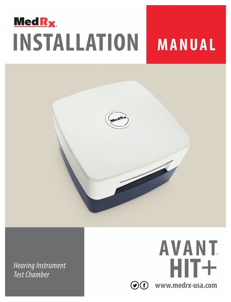
MedRx AVANT HIT+ Installation guide

D-0126021-A 1

D-0126021-A 2
www.medrx-int.com
1200 Starkey Rd., #105, Largo, FL 33771 U.S.A.
Toll Free: (888) 392-1234 • (727) 584-9600
Fax: (727) 584-9602 • Email: medrx@medrx-usa.com
www.medrx-usa.com
Distributor: MedRx International
c/o MAICO Diagnostics GmbH
Sickingenstr. 70-71, 10553 Berlin, Germany
Tel.: +49 30/70 71 46-50
Fax: +49 30/70 71 46-99
E-mail: medrx-[email protected]
Web: www.medrx-int.com

D-0126021-A 3
Contents
Getting to Know Your AVANT HIT+..............................................................................................................................................................................................4
Accessories ..................................................................................................................................................................................................................................5
Setting up the Reference & Coupler Mic.....................................................................................................................................................................................6
HIT MODULE Studio Software Overview ....................................................................................................................................................................................7
HIT Module .................................................................................................................................................................................................................................8
Tool Bars......................................................................................................................................................................................................................................8
Calibrate Coupler Response and HIT Box Verification ..............................................................................................................................................................11
Performing HIT+ Measurements ...............................................................................................................................................................................................12
Attaching Hearing Instruments to the Coupler .........................................................................................................................................................................12
Battery Pills................................................................................................................................................................................................................................13
Setting Up the Hearing Instrument for HIT Measurements......................................................................................................................................................13
Positioning Hearing Instruments in the Test Chamber .............................................................................................................................................................14
Standard HIT Protocol ...............................................................................................................................................................................................................15
Sample HIT Measurements .......................................................................................................................................................................................................15
Printing ......................................................................................................................................................................................................................................18
EMC Precautions .......................................................................................................................................................................................................................20
Safety.........................................................................................................................................................................................................................................24
Symbols that may be used ........................................................................................................................................................................................................24
Technical Information ...............................................................................................................................................................................................................25
Routine checking and subjective tests ......................................................................................................................................................................................25
Limited Warranty.......................................................................................................................................................................................................................26

D-0126021-A 4
Hearing Instrument Testing (HIT) measures the hearing instrument response in a 2cc
coupler in the test chamber. The coupler response is then compared to the
manufacturer specification to ensure quality performance or to detect possible
malfunctions of the hearing instrument.
This system follows the ANSI S3.22 and IEC 60118-7 standards for hearing aid
measurement methods.
The Avant HIT+ supports the following measurements:
OSPL-90 Frequency Response
Input/Output (AGC) Induction Coil
Full on Gain Equivalent Input Noise
Battery Current Reference Test Gain
Harmonic Distortion Attack/Release
This manual assumes that the system hardware, software and drivers are installed
and working properly. Please refer to the MedRx Avant HIT+ Installation Manual for
assistance.
Getting to Know
Your AVANT HIT+
Intended Use Statement:
The MedRx AVANT HIT device is an acoustic chamber that utilizes loudspeakers and
measurement microphones for verification of overall performance of hearing aids
for adults and children. The measurements are made without the hearing instrument
being worn. These devices are to be operated by professionals with education
and/or training in the field of audiometry.
Indication for Use Statement:
The Avant HIT Chambers are for use by professionals with education and/or training
in the field of audiometry to evaluate the overall performance of hearing aids for
adults and children utilizing loudspeakers and measurement microphones. The
measurements are made without the hearing instrument being worn.
The AVANT HIT+ represents a new era of precision Hearing Instrument Testing for
your office. Compact yet rugged, this PC-Based system is USB powered and performs
all required ANSI and IEC tests. The following section of this manual will familiarize
you with the physical features and accessories of the HIT+ system.

D-0126021-A 5
Accessories
Couplers & Adapters
The system includes the couplers and adapters shown above. These will
allow you to perform all ANSI and IEC Hearing Instrument Tests.
NOTE: There is a flexible O-ring inside both the 2cc Coupler and the Body
Adapter. These must remain in place for the couplers to function properly.
Replacement O-rings are available from MedRx. The Allen Wrench is used
when removing the Reference Microphone for re-calibration or replacement.
Coupler Mic
Take care when handling these
components as they are delicate precision
calibrated instruments.
Battery Pills
Battery Pills, also known as Battery Simulators, provide power to the hearing
instrument during testing. The system includes a complete set of Battery Pills
as shown above.

D-0126021-A 6
Setting up the Reference &
Coupler Mic
The Reference Microphone (blue) is pre-installed at the factory.
Carefully install the Coupler Microphone (green) as shown. Take care when
handling these components as they are delicate precision calibrated
instruments.
The Coupler Microphone plug is “keyed”. The arrowhead molded into the
green plug must face the front of the Avant HIT+ when installed.

D-0126021-A 7
HIT MODULE
Studio Software Overview
The MedRx Studio software can run stand-alone or from NOAHSystem or
the TIMSNOAH-Compatible Office System.
Launching the MedRx Studio Software
Stand Alone
•Double click the MedRx Studio shortcut on your Windows
desktop.
NOAH
•Launch NOAH.
•Select a patient.
•Launch MedRx Studio module following NOAH procedures.
Basic Software Options
Several options are available which allow the user to customize the MedRx
Studio software to meet their needs.
Access these options by clicking the settings wheel in the top
right menu bar.
The MedRx Studio software main screen.
Icons are selectable depending on your equipment.

D-0126021-A 8
The Main Screen settings allows you to set the default modules, database,
print templates and more.
If you have more than one MedRx product you can show/hide modules in
the Main Screen settings.
NOTE:Remember, more information is always available in the Interactive
Help System by clicking the “?” Icon in the top right corner of the software
or pressing the F1 key.
HIT Module
Select HIT from the main menu.
Tool Bars
Top Tool Bar
The Tool Bar icons have the following functions:
1. Save Session and Exit
2. Save Session
3. Print
4. Show Journal
5. Show Settings
6. Show Help
7. More Options
The More Options icons have the following functions:
1. Save the Current Session to a File
2. Open session from a file
3. Clear Data from Current Test
4. Open HitBox Verification

D-0126021-A 9
Side Tool Bar
1. On the right side of the screen,
Hearing Aid Ear Selection is
displayed.
2. Hearing Aid Serial Number and
Type of Hearing Aid.
3. Test Set-up window.
4. Stimulus Selection (Select Speech
Noise, ICRA, to evaluate the
performance of noise reduction
circuits).
5. Precalibrate Function. This function allows you to calibrate the
reference level without the hearing aid turned on and then run the
tests without referencing. (Precalibrate can be used if it is suspected
that a high gain hearing aid is leaking sound thus affecting the
reference microphone).
Settings Auto Test Preferences and Procedure Options
1. In the Test Set-Up Window, add
or remove the tests you want to
include in your Auto Test Battery
by clicking on the red X or green
check mark. The tests with the
green check mark will run when
clicking on the Start Auto Button.
2. Click Start to run a single test
that is selected in the Test Set-up
Window. The test will finish after
the measurement is complete.
3. Click MSC (Manual Signal Control) to start a single test in continuous
mode. The test will not finish by itself and will have to be stopped by
clicking Stop icon.
4. Click Start Auto to run the selected tests in sequence.

D-0126021-A 10
Configuring the HIT Software
It is important to note that each module will have different
setting available for customization.
Enter the module and click the settings wheel to customize.
To navigate the settings you will:
•Select the group of settings from the header (1).
•Then choose the setting options from the left sidebar (2).
•The customization options will change based on the group and
settings chosen in the main body (3).
Under Hearing Aid, select the appropriate hearing instrument, battery
type, voltage and test frequencies. You can also load and save hearing
aid defaults.
To select your displayed stimuli, under general, select signal. Click on
each stimulus to display on the main page as dictated by your clinic
policies or jurisdiction’s regulations.
For ANSI and IEC tests, Tone is used as the stimulus.

D-0126021-A 11
Calibrate Coupler Response
and HIT Box Verification
Place the coupler microphone (green) between 2 and 8mm from the
reference microphone (blue). Use the large O-ring to raise the coupler mic to
the same level as the reference microphone as shown in picture below.
In the Studio software go up to the top right menu bar:
•Click the three vertical dots.
•Click on the check mark. The HIT Box Verification widow
will pop-up.
Click start and blue lines will show up on top of the calibration lines. Those
lines will turn green when that calibration test passes or will they will turn
red if that test fails. See picture below.
If you do not get green calibration line responses, make sure the coupler mic
is in the proper position and re-run the calibration.

D-0126021-A 12
Performing HIT+ Measurements
Hearing Instrument Test (HIT) Box standards and procedures are defined by ANSI and IEC. Each test has separate reference and tolerances that can be located in the
interactive help files of our software by clicking the “?” Icon or pressing the F1 key. Please refer to these for additional information about each test
Attaching Hearing Instruments to the Coupler
ITE (In the Ear), ITC (In the Canal)
and MIC (Mini Canal) Hearing Instruments
1. Seal acoustic vents.
2. Wrap the canal portion of the instrument with a
hermetic sealing material such as Bostik Blu-Tack.
3. Align the sound bore with the opening of the ITE
coupler adapter. Press the sealing material firmly
into the ITE adapter.
4. Ensure that the black O-ring is installed in the 2cc
coupler and snap the ITE adapter in place.
RIC (Receiver in Canal) Hearing Instruments
1. The ITE Coupler adaptor should be used for
RIC’s
2. Wrap the receiver (without a dome) with a
hermetic sealing material such as Bostik Blu-
Tack.
3. Align the receiver with the opening of the ITE
coupler adapter. Press the sealing material
firmly into the ITE adapter.
4. Ensure that the black O-ring is installed in the
2cc coupler and snap the ITE adapter in place.
NOTE: If the RIC hearing aid has an earmold it can
remain on the hearing aid and be attached to the
coupler in the same method as an ITE hearing aid.

D-0126021-A 13
BTE (Behind The Ear)
Hearing Instruments
1. Remove the earmold from the hearing
instrument.
2. Attach the ear hook to the 20mm long Tygon
tube on BTE Coupler Adapter.
3. Snap the BTE Coupler Adapter onto the 2cc
Coupler.
Battery Pills
•If performing Battery Current test, place the battery pill in hearing
instrument. If not, place a new battery in the instrument or make sure
the instrument is properly charged.
•Battery pills are used for ITE and BTE Instruments.
*Note: Battery Current can also be performed on its own after the
selected battery of tests are completed. Battery Current testing cannot
be done with rechargeable or body worn instruments.
Setting Up the Hearing
Instrument for HIT
Measurements
1. Open manufacture’s hearing aid fitting software and connect
hearing aid.
2. The hearing instrument should be set to Full-On Gain mode for
OSPL90 and Full-On Gain tests and then will need to be adjusted to
Reference Test Gain mode for Frequency Response, Equiv. Input
Noise, Harmonic Distortion, Battery Current, Input-Output, and
Attack/Release.
*Note: The location of each manufacture’s test box mode varies. If
necessary, please contact the hearing aid manufacturer to see
where this setting can be found in their fitting software. If test box
mode is not available, set to Real Ear Mode (REM) and increase
overall gain until hearing aid is at full-on gain.

D-0126021-A 14
Positioning Hearing
Instruments in the Test
Chamber
The AVANT HIT+ chamber utilizes a speaker located below the test surface.
When placing hearing instruments in the chamber, it is critical to place the
hearing instrument microphone adjacent to the reference microphone. The
center of the sound inlet of the hearing instrument microphone should be
between 2mm and 8mm from the center of the reference microphone. The
hearing instrument’s sound inlet should be directly above the fan shaped
marking on the test surface, and at the same distance (height) above the
foam surface of the test chamber as the reference microphone inlet. Proper
positioning for ITE, BTE and RIC hearing instruments are shown below.
Once the instrument is properly placed in the test chamber be sure the
hearing aid is on and connected to your fitting software and close the lid of
the chamber.
Note: If necessary, a neck loop or other connection device can be placed
inside the test box around the hearing instrument. Wireless programmers
will still maintain connection even when the box is closed.
BTE Hearing Instrument
ITE Hearing Instrument
RIC Hearing Instrument

D-0126021-A 15
Standard HIT Protocol
The MedRx Studio HIT software is designed to make the process of making
HIT measurements simple. The easiest way to complete them is to use the
Auto Test feature.
1. Once the hearing instrument is in a Full-On Gain mode and positioned in
the test box as stated in the previous section, you can either run each test
individually by clicking on the Start button or perform as many tests as
you wish automatically by clicking on the Start Auto button.
a.In order to use the Start Auto feature, you must select each test that
you want to run by clicking on the red X next to it and it will change
to a green check mark. All tests with the green check mark will run
after clicking on the Start Auto button.
2. Once the OSPL90 and Full-On Gain tests are completed, a prompt will
instruct you to adjust the hearing aids settings to Reference Test Gain
before moving on to the next test.
3. Put the hearing aids into a RTG mode in your manufactures software to
match the RTG displayed as close as possible. The calculated RTG is based
on OSPL90 and Full-On Gain measurements.
*Note: If software does not have test box mode and you are using real ear
mode at full on gain, then lower overall gain until measured output
reaches the RTG.
4. Once at RTG click Accept to continue to Frequency Response, Equiv. Input
Noise, Harmonic Distortion, Battery Current, Input-Output, and
Attack/Release.
Sample HIT
Measurements
The screenshots below illustrate the Avant HIT+ representations
of the ANSI S3.22-2009 Hearing Instrument Test Battery. The
system also supports the IEC 60118-7 2005-10.
Many manufacturers include a technical data sheet with the
hearing instruments to compare your measurement results to.
They can also commonly be found in the fitting software or online
on the manufacture’s website. If you cannot locate the specs
sheet or the manufacturer does not send one, you can simply call
and request one be sent with each hearing aid.
References and tolerances for each test can be found in the
interactive help files by clicking the “?” Icon or pressing the F1
key.
OSPL90

D-0126021-A 16
Full-On Gain
Reference Test Gain
Frequency Response
Equivalent Input Noise
Total Harmonic Distortion
Battery Current

D-0126021-A 17
Input/Output
Attack and Release
Induction Coil

D-0126021-A 18
Printing
Printing within the MedRx Studio software. You can use the templates
provided at installation or create your own templates to suit your needs.
Icons in the Print Window
1. Create a new template.
2. Preview template icon.
3. Print template icon.
4. Select the template you would like to use.
5. Shortcut to templates folder on your desktop.
6. Studio Help icon.
7. Edit the template with the pencil icon. Editing a template will open
the print editor and allow you to adjust print elements.
8. Duplicate existing templates icon.
9. Delete template icon.
To Use an Existing Print Template
1. Click the print icon in the top tool bar or hold down the Ctrl key
and click the P key on your keyboard.
2. Select the template you would
like to use.
3. Click the print
preview icon to see
the patient’s data & images on
the template before printing.
4. Click the print icon.
5. The printer options box will
pop-up.
6. Click print.
7. Or click Ctrl+Shift+P to print
the modules default template.

D-0126021-A 19
Create New Print Templates
1. Select the printer icon.
2. Select the + icon to create a new
template.
3. Name the template you are creating.
4. Choose page orientation.
5. Use the drop-down menu to choose the size
of paper you will be using.
6. In the bottom left, Page Zoom will allow you
to zoom in/out of the template for easier
editing.
7. In the bottom left, the Page Margin is set by
default to the ideal level. Adjusting this will
determine how far items will print from the
edges.
8. Drag and drop elements onto the page to
create your template.
a. You can combine data from multiple
modules into a single template.
b. Elements may overlap and will
stack/cover previously added
elements.
c. Certain elements will have settings
that can be adjusted after dropping
onto the page.
d. You can resize all elements. The
contents of each element will resize
within the box depending on the
amount of data in the element.
9. Use the + button to add additional pages
if needed.
10. After template completion, use the Save,
Save As, Preview and Print Icons for your
template.
Saved templates will be available for future sessions.
Print a template to ensure that all elements print as expected.

D-0126021-A 20
EMC Precautions
The Avant Hearing Instrument Test (HIT) Box needs special precautions regarding EMC and needs to be installed according to the following EMC information.
List of all cables and maximum lengths of cables, transducers and accessories:
Transducer / Accessories
Maximum Cable length
USB Cable
2.9 meters
Battery Simulators (All Versions)
0.3 meters
Microphones (All Version)
0.3 meters
Warnings!
•The use of accessories, transducers and cables other than those specified, with the exception of transducers and cables sold by the manufacturer of the
Avant Hearing Instrument Test box as replacement parts for internal components, may result in increased emissions or decreased immunity of the Avant
Hearing Instrument Test Box.
•The Avant Hearing Instrument Test Box should not be used adjacent to or stacked with other equipment. If adjacent or stacked use is necessary, the Avant
Hearing Instrument Test Box should be observed to verify normal operation in the configuration in which it will be used.
•The Avant Hearing Instrument Test Box may be interfered with by other equipment, even if that other equipment complies with CISPR emission
requirements.
•The Avant Hearing Instrument Test Box does not have a life supporting function.
•Portable and mobile RF communications equipment can affect the Avant Hearing Instrument Test Box.
Other manuals for AVANT HIT+
1
Table of contents
Other MedRx Test Equipment manuals
Popular Test Equipment manuals by other brands
Sartorius
Sartorius mLINE user manual
SmartSafe
SmartSafe iSmartIMMO 801 user manual

Emerson
Emerson Rosemount 5900 Instruction for Installation, Configuration, and Operation
pico Technology
pico Technology PicoScope 2000 Series user guide
Slaughter
Slaughter 2925 Operation and service manual
Keysight Technologies
Keysight Technologies InfiniVision 6000L Series Service guide
