Emerson Rosemount 5900 Quick guide

Reference Manual
00809-0200-5900, Rev AD
February2023
Rosemount 5900 Proof Test
Instruction for Installation, Configuration, and Operation
of Proof Test Function with Reference Reflector

Rosemount™ 5900 Radar Level Gauge
NOTICE
Read this manual before working with the product. For personal and system safety, and for optimum product
performance, ensure you thoroughly understand the contents before installing, using, or maintaining this product.
For equipment service or support needs, contact your local Emerson Automation Solutions/Rosemount Tank Gauging
representative.
Spare Parts
Any substitution of non-recognized spare parts may jeopardize safety. Repair, e.g. substitution of components etc,
may also jeopardize safety and is under no circumstances allowed.
Rosemount Tank Radar AB will not take any responsibility for faults, accidents, etc caused by non-recognized spare
parts or any repair which is not made by Rosemount Tank Radar AB.
CAUTION
The products described in this document are NOT designed for nuclear-qualified applications. Using non-nuclear
qualified products in applications that require nuclear-qualified hardware or products may cause inaccurate readings.
For information on Rosemount nuclear-qualified products, contact your local Emerson Sales Representative.
CAUTION
Handle the wire and assembly with care to avoid permanent bends.
WARNING
Failure to follow safe installation and servicing guidelines could result in death or serious injury.
Ensure only qualified personnel perform the installation.
Use the equipment only as specified in this manual. Failure to do so may impair the protection provided by the
equipment.
Do not perform any service other than those contained in this manual unless you are qualified.
WARNING
High voltage that may be present on leads could cause electrical shock.
Avoid contact with the leads and terminals.
Ensure the mains power to the device is off and the lines to any other external power source are disconnected or not
powered while wiring the device.
WARNING
Electrical shock could cause death or serious injury.
Use extreme caution when making contact with the leads and terminals.
2

WARNING
Physical access
Unauthorized personnel may potentially cause significant damage to and/or misconfiguration of end users’
equipment. This could be intentional or unintentional and needs to be protected against.
Physical security is an important part of any security program and fundamental to protecting your system. Restrict
physical access by unauthorized personnel to protect end users’ assets. This is true for all systems used within the
facility.
3

4

Contents
Chapter 1 Introduction...............................................................................................................................7
1.1 Section overview..........................................................................................................................8
1.2 Service support............................................................................................................................ 8
1.3 Installation procedure ............................................................................................................... 8
1.4 Firmware requirements for proof testing................................................................................ 9
Chapter 2 Installation...............................................................................................................................11
2.1 Overview.....................................................................................................................................11
2.2 Installation considerations.......................................................................................................11
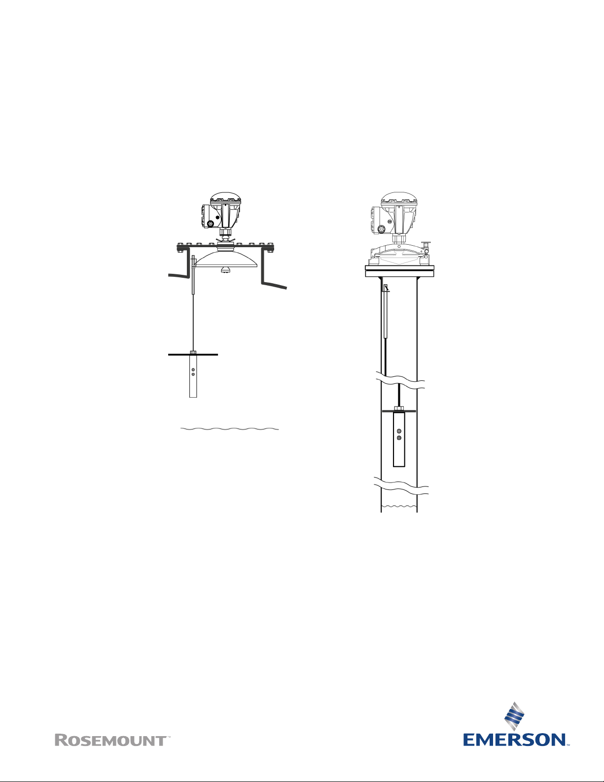
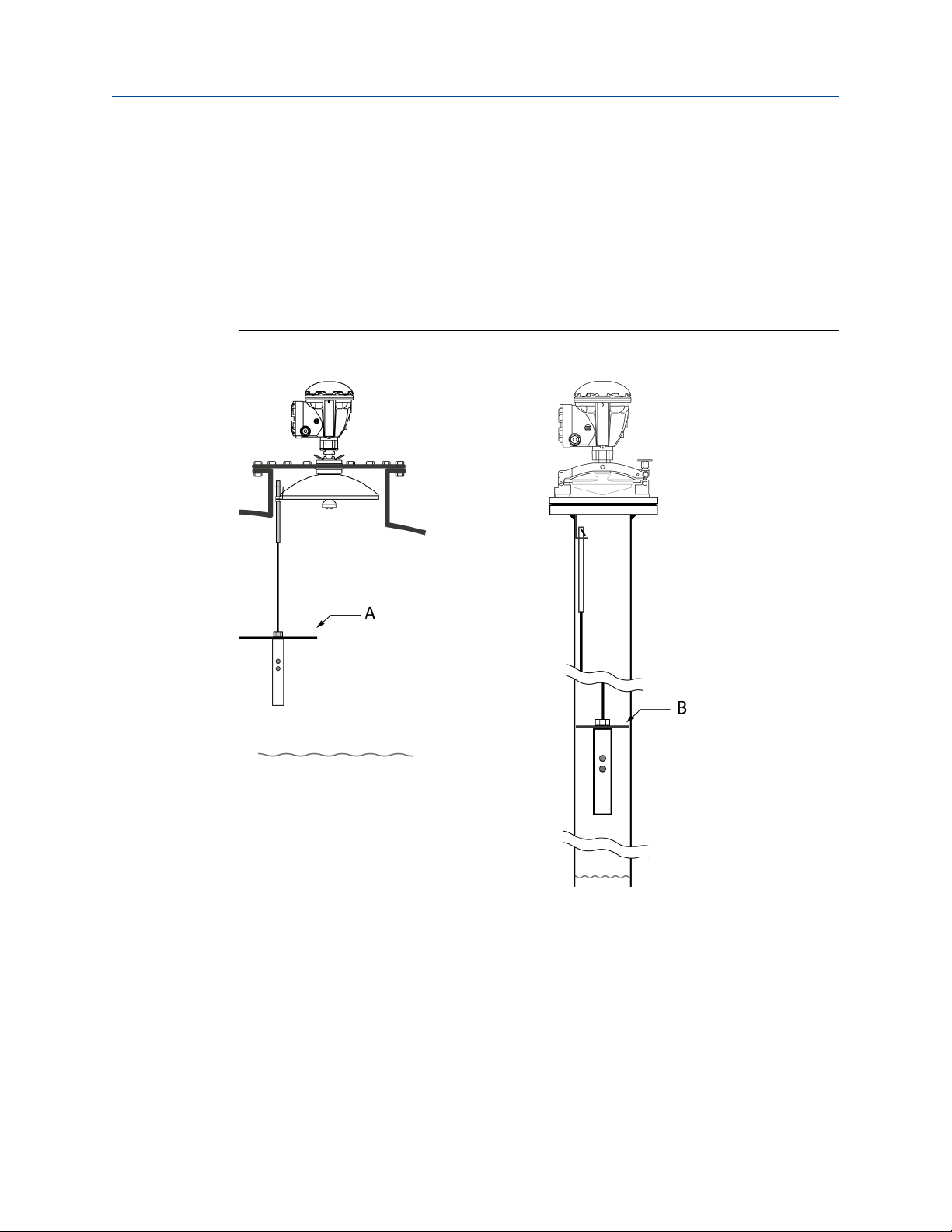
2.3 Install the Reference Reflector for Parabolic antenna..........................................................11
2.4 Install the Reference Reflector for Array antenna................................................................ 24
Chapter 3 Configuration of reference reflector.................................................................................... 35
3.1 Overview.....................................................................................................................................35
3.2 Configuration using TankMaster WinSetup...........................................................................35
Chapter 4 Operation................................................................................................................................. 45
4.1 Proof Test operation................................................................................................................. 45
4.2 Scheduling..................................................................................................................................49
4.3 History.........................................................................................................................................51
4.4 Reports....................................................................................................................................... 52
4.5 Removing a Reference Reflector............................................................................................. 54
Chapter 5 Service and troubleshooting................................................................................................. 57
5.1 Troubleshooting........................................................................................................................ 57
5.2 Tank scan....................................................................................................................................59
Reference Manual Contents
00809-0200-5900 February2023
Rosemount 5900 5

Contents Reference Manual
February2023 00809-0200-5900
6 Emerson.com/Rosemount

1 Introduction
The Rosemount 5900 Radar Level Gauge is designed with functionality that lets you proof
test high alarms and verify correct product surface measurement. The Rosemount 5900
allows you to combine continuous product level monitoring with proof testing at regular
intervals. It is based on a dedicated Reference Reflector that introduces a radar echo at a
predefined position in the tank.
Figure 1-1: The Rosemount 5900 can be equipped with an optional Reference Reflector
that allows proof testing the gauge on a regular basis
A. Reference Reflector and parabolic antenna
B. Reference Reflector and array antenna
Reference Manual Introduction
00809-0200-5900 February2023
Rosemount 5900 7

1.1 Section overview
This document is a supplement to the Rosemount 5900S Reference Manual. The sections
in this reference manual provide information on installing, operating, and maintaining the
Rosemount 5900 Proof Test System. The sections are organized as follows:
Section 1 Introduction gives a brief introduction to the Rosemount 5900 Proof Test
function and the recommended installation procedure.
Section 2 Installation provides instructions on how to install the Reference Reflector on
the Rosemount 5900 with Parabolic Antenna and Array Antenna.
Section 3 Configuration of Reference Reflector contains instructions on how to
calibrate and configure the Rosemount 5900 Proof Test function.
Section 4 Operation provides instructions for how to use the proof test function.
Section 5 Service and Troubleshooting provides troubleshooting techniques for the
most common operating problems.
1.2 Service support
For service support contact the nearest Emerson /Rosemount Tank Gauging
representative. Contact information can be found on the web site www.Emerson.com/
Rosemount Tank Gauging.
1.3 Installation procedure
Follow these steps for proper installation and configuration of the proof test reference
reflector:
Procedure
1. Review installation considerations.
2. Mount the proof test reference reflector.
3. Wire the Rosemount 5900 gauge.
4. Ensure covers and cable gland/conduit connections are tight.
5. Configure the Rosemount 5900 for proof testing.
6. Verify operation.
Related information
Rosemount 5900S Reference Manual
Rosemount 5900C Reference Manual
Installation considerations
Install the Reference Reflector for Parabolic antenna
Install the Reference Reflector for Array antenna
Configuration of reference reflector
Introduction Reference Manual
February2023 00809-0200-5900
8 Emerson.com/Rosemount

1.4 Firmware requirements for proof testing
Consider the following proof test requirements for wired and wireless applications
respectively.
Wired proof test function requires:
•gauge firmware version 1.B9 or higher
•Rosemount TankMaster 6.E1 or higher
For wireless applications the proof test function requires:
•Rosemount 5900 and Rosemount 2410 ordered with model code safety certification
option "S"
•Rosemount TankMaster 6.G0 or higher
Reference Manual Introduction
00809-0200-5900 February2023
Rosemount 5900 9

Introduction Reference Manual
February2023 00809-0200-5900
10 Emerson.com/Rosemount

2 Installation
Related information
Configuration procedure
2.1 Overview
The information in this section covers configuration and calibration of the Reference
Reflector for proof testing the Rosemount 5900 Radar Level Gauge.
2.2 Installation considerations
Before you start installing the Reference Reflector, ensure that the following items are
considered in order to fulfill the installation requirements for the Reference Reflector at the
desired position:
•Maximum product level in the tank
•High Alarm position
•Minimum / maximum distance between Gauge Reference Point and Reference
Reflector
Note
The Reference Reflector for Array Antenna may need to be removed to allow product
sampling through the Still-pipe.
Related information
Tank geometry parabolic antenna
Tank geometry array antenna
2.3 Install the Reference Reflector for Parabolic
antenna
The Reference Reflector is installed under the antenna. It is attached to a wire fixed to the
Parabolic Antenna. The Reference Reflector introduces a radar echo that is used for proof
testing the Rosemount 5900 Radar Level Gauge. Proof testing can be performed without
the need to open the tank.
2.3.1 Reference Reflector kit
The Reference Reflector is delivered with all parts needed for proper installation on a
Rosemount 5900 with Parabolic Antenna. The Reference Reflector kit includes the following
parts:
•Wire assembly
•Weight assembly
•Reference Reflector
•Clamp ring
Reference Manual Installation
00809-0200-5900 February2023
Rosemount 5900 11

Figure 2-1: Wire and Weight Assembly
A. Nut M8
B. Spring washer
C. Washer
D. M8 terminal
E. Wire diameter 4 mm (0.16 in.)
Length 5 m (16.4 ft.)
F. Nut M12
G. Weight
H. M6 screw (x2)
Allen key size 3
Figure 2-2: Reference Reflector
Installation Reference Manual
February2023 00809-0200-5900
12 Emerson.com/Rosemount

Figure 2-3: Clamp Ring
A. M6 cylinder nut
B. M6 screw
C. Clamping ring
Reference Manual Installation
00809-0200-5900 February2023
Rosemount 5900 13

2.3.2 Tank geometry parabolic antenna
Figure 2-4: Tank geometry for Rosemount 5900 with Parabolic Antenna and Proof Test
Reference Reflector
A. Reference Reflector (RR). Maximum inclination 2.5°.
B. Weight
C. Clamping ring
D. Parabolic antenna
E. Gauge Reference Point
F. Reference Reflector (RR) distance
G. Reference Reflector (RR) position
H. Wire distance
I. Minimum 500 mm (19.7 in.)
J. Maximum product level
K. Zero Level
Reference Reflector distance:
•Minimum 600 mm (24 in.)
•Maximum 5000 mm (200 in.)
Note
See Safety Instrumented System (SIS) for installation requirements in Safety Instrumented
Systems (SIS).
Installation Reference Manual
February2023 00809-0200-5900
14 Emerson.com/Rosemount

Related information
Configuration procedure
Safety Instrumented System (SIS)
This is a brief introduction to tank geometry for the Rosemount 5900 with Parabolic
antenna and proof test reference reflector in a Safety Instrumented System (SIS)(1).
Procedure
1. Decide position of SIL High Alarm.
2. Find a position for the Reference Reflector (RR) that fulfills the following
requirements:
a. Minimum 500 mm above SIL High Alarm Limit
b. Distance Reference Reflector - Gauge Reference Point: 600 to 5000 mm
c. Minimum 500 mm to maximum product level
Figure 2-5: Tank geometry with Parabolic Antenna and Proof Test Reference
Reflector in Safety Instrumented System (SIS).
A. SIL Surface Distance
B. SIL High Alarm Limit
C. Distance Reference Reflector - Gauge Reference Point: 600 to 5000 mm
D. Minimum distance Reference Reflector - SIL High Alarm = 500 mm
E. Reference Reflector (RR)
F. Maximum product level
G. Gauge Reference Point
(1) In the Rosemount 5900 and 2410 Safety Manual (Document No. 00809-0200-5100) you will find more
information on how to install and configure the Rosemount 5900 Radar Level Gauge and 2410 Tank Hub
in a Safety Instrumented System.
Reference Manual Installation
00809-0200-5900 February2023
Rosemount 5900 15

2.3.3 Install the reference reflector
This is a description of how to install a reference reflector on a Parabolic antenna. It also
describes how to calculate the required Wire Distance parameter.
Prerequisites
The length of the wire (Wire Distance) that holds the Reference Reflector needs to be
calculated before the Reference Reflector can be installed in the tank. The wire must be
long enough to allow the reflector to be properly positioned in the tank including the
weight that is attached under the reflector.
CAUTION
Handle the wire and assembly with care to avoid permanent bends.
Procedure
1. Specify the position of the Reference Reflector (RR) and calculate the Reference
Reflector Distance (see Figure 2-4 and Figure 2-7).
2. Choose the appropriate reflector size. As a result of the radar beam geometry, a
smaller reflector can be used further away from the radar gauge. There are four
different Reference Reflectors to choose from depending on the Reference Reflector
Distance as shown in Table 2-1.
Table 2-1: Reference Reflector Size
Reference Reflector Distance (mm/inch) Diameter (mm/inch)
600 to 2000 (24 to 79) 250 (10)
2000 to 3000 (79 to 118) 200 (7.9)
3000 to 4000 (118 to 157) 135 (5.3)
4000 to 5000 (157 to 197) 90 (3.5)
3. Mount the appropriate Reference Reflector on the weight.
Installation Reference Manual
February2023 00809-0200-5900
16 Emerson.com/Rosemount

6. Feed the wire through the weight and the Reference Reflector (RR).
A. Wire Distance
B. Reference Reflector
C. Weight
D. M6 x 2. Allen key size 3. Torque 2.5 Nm.
E. Cut wire 0 - 150 mm under the weight.
7. Place the weight in the calculated Wire Distance position.
8. Tighten the two screws (size M6) to a torque value of 2.5 Nm.
9. Cut the wire. You may leave 0 to 150 mm (0 to 6 in.) of the wire below the weight.
Installation Reference Manual
February2023 00809-0200-5900
18 Emerson.com/Rosemount

10. Mount the clamping ring on the Parabolic Antenna. Ensure that the Reference
Reflector is directed towards the center of the tank (see Figure 2-6).
A. Parabolic antenna
B. Clamping ring
C. M6 screw
Torque=2.3 Nm
11. Mount the M8 terminal (that holds the weight and Reference Reflector) on the
clamping ring.
12. Tighten the M8 nut to the specified torque of 8 Nm.
A. Nut M8
Torque=8 Nm
B. Spring washer
C. Washer
D. Nut M8
E. M8 terminal
F. Wire
G. Antenna
H. Clamping ring
I. Tank center
Reference Manual Installation
00809-0200-5900 February2023
Rosemount 5900 19

13. Ensure that:
•the Reference Reflector is correctly aligned towards the center of the tank
•inclination of Reference Reflector is less than 2.5°
Figure 2-6: Align the Reference Reflector
A. Reference Reflector (RR)
B. Tank center
C. Parabolic antenna
D. Tank wall
Related information
Tank geometry parabolic antenna
Wire Distance calculation
Installation Reference Manual
February2023 00809-0200-5900
20 Emerson.com/Rosemount
Other manuals for Rosemount 5900
4
Table of contents
Other Emerson Test Equipment manuals
Popular Test Equipment manuals by other brands

Rohde & Schwarz
Rohde & Schwarz RTP-K110 user manual

ATE
ATE BFT 320 Operator's manual

MULTI MEASURING INSTRUMENTS
MULTI MEASURING INSTRUMENTS MLIT-1 instruction manual

Bacharach
Bacharach Fyrite INSIGHT Operating & maintenance instructions

Tenma
Tenma 72-2650 user manual

Covita
Covita Smokerlyzer Instructions and tips