SmartSafe iSmartIMMO 801 User manual

iSmartIMMO 801 User Manuall
i
Copyright Information
Copyright © 2021 by SHENZHEN SMARTSAFE TECH CO., LTD. (Hereinafter refer to
"SmartSafe"). All rights reserved. No part of this publication may be reproduced, stored
in a retrieval system, or transmitted in any form or by any means, electronic, mechanical,
photocopying and recording or otherwise, without the prior written permission.
Statement: SmartSafe owns the complete intellectual property rights for the software
used by this product. For any reverse engineering or cracking actions against the
software, SmartSafe will block the use of this product and reserve the right to pursue its
legal liabilities.
Disclaimer of Warranties and Limitation of Liabilities
All information, illustrations, and specifications in this manual are based on the latest
information available at the time of publication.
The right is reserved to make changes at any time without notice. We shall not be liable
for any direct, special, incidental, indirect damages or any economic consequential
damages (including the loss of profits) due to the use of the document.
Important Safety Precautions
To avoid personal injury, property damage, or accidental damage to the product, read
all of the information in this section before using the tool.
DANGER
When an engine is operating, keep the service area well-ventilated or attach a
building exhaust removal system to the engine exhaust system. Engines produce
various poisonous compounds (hydrocarbon, carbon monoxide, nitrogen oxides, etc.)
that cause slower reaction time and result in death or serious personal injury.
Please use the included battery and power adaptor. Risk of explosion if the battery
is replaced with an incorrect type.
DO NOT attempt to operate the tool while driving the vehicle. Have a second person
to operate the tool. Any distraction may cause an accident.
WARNING
Always perform automotive testing in a safe environment.
Do not connect or disconnect any test equipment while the engine is running.
Before starting the engine, put the gear lever in the Neutral position (for manual
transmission) or in the Park (for automatic transmission) position to avoid injury.
NEVER smoke or allow a spark or flame in vicinity of battery or engine. Do not
operate the tool in explosive atmospheres, such as in the presence of flammable
liquids, gases, or heavy dust.
Keep a fire extinguisher suitable for gasoline/chemical/electrical fires nearby.

iSmartIMMO 801 User Manuall
ii
Wear an ANSI-approved eye shield when testing or repairing vehicles.
Put blocks in front of the drive wheels and never leave the vehicle unattended while
testing.
Use extreme caution when working around the ignition coil, distributor cap, ignition
wires and spark plugs. These components create hazardous voltage when the
engine is running.
To avoid damaging the tool or generating false data, please make sure the vehicle
battery is fully charged and the connection to the vehicle DLC (Data Link Connector)
is clear and secure.
Automotive batteries contain sulfuric acid that is harmful to the skin. In operation,
direct contact with the automotive batteries should be avoided. Keep the ignition
sources away from the battery at all times.
Keep the tool dry, clean, free from oil, water or grease. Use a mild detergent on a
clean cloth to clear the outside of the equipment when necessary.
Keep clothing, hair, hands, tools, test equipment, etc. away from all moving or hot
engine parts.
Store the tool and accessories in a locked area out of the reach of children.
Do not use the tool while standing in water.
Do not expose the tool or power adapter to rain or wet conditions. Water entering
the tool or power adaptor increases the risk of electric shock.
This tool is a sealed unit. There are no end-user serviceable parts inside. All internal
repairs must be done by an authorized repair facility or qualified technician. If there
is any inquiry, please contact the dealer.
Keep the tool far away from magnetic devices because its radiations can damage
the screen and erase the data stored on the tool.
Do not attempt to replace the internal rechargeable lithium battery. Contact the
dealer for factory replacement.
Do not disconnect the battery or any wiring cables in the vehicle when the ignition
switch is on, as this could avoid damage to the sensors or the ECU.
Do not place any magnetic objects near the ECU. Disconnect the power supply to
the ECU before performing any welding operations on the vehicle.
Use extreme caution when performing any operations near the ECU or sensors.
Ground yourself when you disassemble PROM, otherwise ECU and sensors can be
damaged by static electricity.
When reconnecting the ECU harness connector, be sure it is attached firmly,
otherwise electronic elements, such as ICs inside the ECU, can be damaged.

iSmartIMMO 801 User Manuall
iii
Table of Contents
1 Packing List.................................................................................................................... 1
2 Overview..........................................................................................................................2
2.1 Introduction....................................................................................................................2
2.2 Display Tablet................................................................................................................3
2.3 VCI Dongle.................................................................................................................... 4
2.4 iSmartIMMO G3............................................................................................................4
3 Initial Use.........................................................................................................................5
3.1 Charging........................................................................................................................ 5
3.2 Power On & Off.............................................................................................................6
3.3 Basic Operations.......................................................................................................... 6
3.4 Change System Language......................................................................................... 6
3.5 Network Setup.............................................................................................................. 6
3.6 Set Standby Time.........................................................................................................7
3.7 Register & Download Diagnostic Software...............................................................7
4 Getting Started...............................................................................................................8
4.1 Job Menu.......................................................................................................................8
4.2 Connection.................................................................................................................... 8
4.3 Communication Setup................................................................................................. 9
5 Immobilizer Operations............................................................................................... 9
5.1 Anti-theft matching....................................................................................................... 9
5.2 IMMO Programming.................................................................................................. 15
6 Diagnose....................................................................................................................... 28
6.1 VIN SCAN................................................................................................................... 28
6.2 Manual Selection........................................................................................................29
7 Reset.............................................................................................................................. 33
8 Update............................................................................................................................37
9 Feedback....................................................................................................................... 37
10 Personal Center.........................................................................................................38


iSmartIMMO 801 User Manuall
1
1 Packing List
The following accessory items are only for reference. Please consult from the
local agency or check the package list supplied with this tool together.
No.
Item
Descriptions
Qt.
1
iSmartIMMO 801
Main Unit
1
2
VCI
VCI dongle
1
3
iSmartIMMO G3
Immobilizer Programmer
1
4
OBD II Extension
Cable
Connects the VCI dongle to the OBD II vehicle’s
DLC.
1
5
USB Cable
Type C to Type C, for charging.
1
6
Power Adaptor
For charging the tablet.
1
7
USB Cable
(Mini B)
Type A to Mini B, for communication between
tablet and VCI
1
8
Diagnostic Main
Cable
Connects the VCI dongle, iSmartIMMO G3 and the
vehicle’s DLC
1
9
XTA001
Place the EEFROM chip onto the socket, and then
plug it into the programmer socket.
1
10
MCU1
Connect the programmer with MCU(chip soldering
is required in this procedure).
1
11
MCU2
Connect the programmer with MCU(chip soldering
is required in this procedure).
1
12
EEPROM PCBA
Solder the desired chip on the EEPROM
converter, and then plug the board into the
programmer(chip soldering is required)
1
13
MB-Key
Connect the programmer with the key lock, insert
the key into the programmer for further key
operations.
1
14
INS Cable V1
Connect the programmer and vehicle dashboard,
and then place the probe (the yellow lead) to the
designated area.
1

iSmartIMMO 801 User Manuall
2
15
INS Cable V2
After removing the vehicle dashboard, connect
programmer, vehicle dashboard, and the cable.
1
16
MCU Cable V1
To connect the programmer and MCU.
1
17
Bench Mode
Cable
Connect the programmer and the engine to read
engine or gearbox ECU (Connect engine ECU with
the BENCH mode cable based on BENCH mode
diagram).
1
18
Matching Adapter
A
To connect the BENCH mode cable and gearbox
ECU/engine.
5
19
Matching Adapter
B
To connect the BENCH mode cable and gearbox
ECU/engine.
6
20
Matching Adapter
C
To connect the BENCH mode cable and gearbox
ECU/engine.
7
21
Matching Adapter
D
To connect the BENCH mode cable and gearbox
ECU/engine.
8
22
Matching Adapter
E
To connect the BENCH mode cable and gearbox
ECU/engine.
6
23
Switching Power
Supply
Supply power to the programmer.
1
24
Password
Envelope
A piece of paper bearing Product S/N and
Activation Code, which is required for your
registration.
1
25
User Manual
1
2 Overview
2.1 Introduction
iSmartIMMO 801, developed by SHENZHEN SMARTSAFE TECH CO., LTD. is
specially designed as a comprehensive immobilizer programmer. It can work
with the VCI (Vehicle Communication Interface) dongle to perform full car
models and full systems diagnosis (including reading/clearing the diagnostic
trouble codes and reading data stream etc.). Additionally, it also can work with
the iSmartIMMO G3 to perform anti-theft matching and anti-theft programming
operations.

iSmartIMMO 801 User Manuall
3
2.2 Display Tablet
1. Docking slot for VCI dongle - for housing the VCI dongle.
2. VCI dongle -It is pre-installed in the docking slot on the top of the display
tablet. Use the hand to press the dongle once, it will be automatically ejected
from the docking slot. When it is not in use, please reinsert it into the slot to
avoid loss.
3. Power key - Press it to turn the tool on/off.
4. LCD Screen – Indicates the test results.
5. USB Type C port - Connect a charger for charging or data transmission.
6. USB Type A port - Connect the tablet to the VCI dongle via data cable.
7. Rear camera.
Technical Parameters
•CPU: 4-Core 1.8GHz
•Memory: 4GB
•ROM: 64GB
•Screen Size: 8 inches
•Resolution: 1280*800 pixel
•Camera: 8MP rear-facing camera
•Working Voltage: 5V
•Working Current: ≤3A
•Working Environment: 0℃~45℃
•Storage Environment: -10℃~60℃
iSmartIMMO 801 User Manuall
4
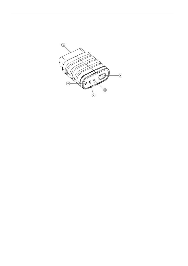
2.3 VCI Dongle
This dongle works as a VCI (Vehicle Communication Interface) device. It is
used to obtain the vehicle data, and then send it to the tablet for analysis via
Bluetooth.
1. OBD-16 diagnostic connector -Connects the OBD-II extension cable or directly
plug into the vehicle's DLC (Data Link Connector) port.
2. Data transmission port -Connects to the display tablet via data cable to perform
vehicle diagnosis.
3. Communication LED -It lights up and keeps flashing when the VCI dongle is
communicating with the tablet.
4. Power LED -It lights up when powered on.
5. Error LED -It lights up when communication failure occurs.
Technical Parameters
•Working Voltage: 12V
•Working Current: ≤60mA
•Working Environment: 0℃~50℃
•Storage Environment: -10℃~60℃
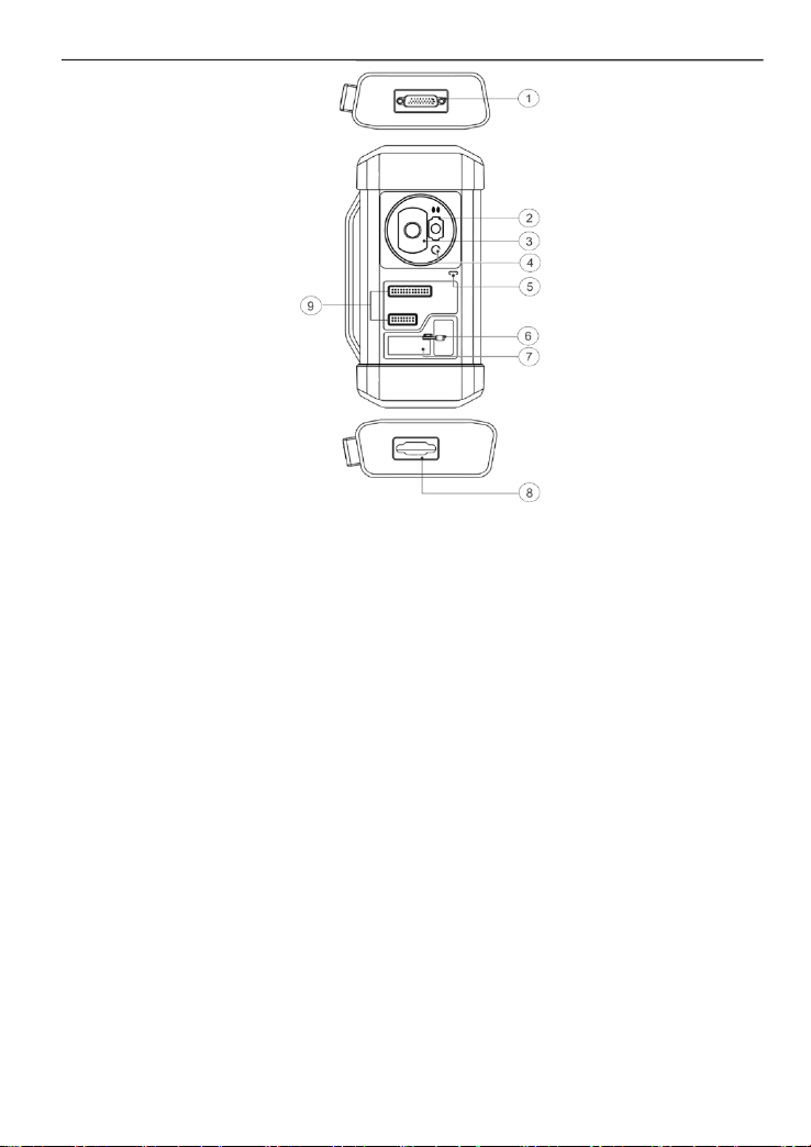
2.4 iSmartIMMO G3
The iSmartIMMO G3 works as a dedicated anti-theft immobilizer programmer. It
needs to work with the display tablet to perform the IMMO Matching (for some
vehicles) and IMMO Programming operations.
iSmartIMMO 801 User Manuall
5
1. DB26 diagnostic connector -Connects with the Mercedes Benz infrared collector,
ECU cable and MCU cable etc.
2. Mercedes Benz infrared key slot -Holds the Mercedes Benz key.
3. Vehicle key slot -Holds the car key for RF defection.
4. Transponder slot -Holds the transponder (key chip).
5. Power LED -Red light indicates faults. Orange light indicates functioning
normally.
6. Valve -Tighten/Loosen the EEPROM board.
7. EEPROM transponder slot -Holds the EEPROM plug-in transponder or
EEPROM socket.
8. DB15 diagnostic connector -Connects with main diagnostic cable.
9. Cross signal pins -Holds the MCU spare cable or vehicle DIY signal cable to
read or write MCU and ECU chips.
Technical Parameters
•Input Voltage: 12 V
•Input Current: 500mA
•Working Environment: 0℃~50℃
•Storage Environment: -20℃~70℃
3 Initial Use
3.1 Charging
Follow the steps below to charge the tablet:
1. Connect one end of the charging cable to the USB socket of the power

iSmartIMMO 801 User Manuall
6
adapter.
2. Connect the other end to the charging port on the bottom of the host.
3. Plug the charger power plug into a power outlet to start charging.
Caution: Please use the included power adaptor to charge your tool. No
responsibility can be assumed for any damage or loss caused as a result of using
power adaptors other than the one supplied.
Note: If the battery remains unused for a long time or the battery is completely
discharged, it is normal that the tool will not power on while being charged. Please
charge it for 5 minutes and then turn it on.
3.2 Power On & Off
Long press the POWER button and then the start interface will appear.
Long press the POWER button until the dialog box pops up, and tap Shutdown to
turn it off or tap Restart to reboot it.
3.3 Basic Operations
Single-tap: To select an item or launch a program.
Double-tap: To zoom in so that the text on a webpage appears in
a column that fits your device’s screen.
Long press: Tap and hold on the desired vehicle software to
delete it.
Slide: To jump to different pages.
Swipe from the right edge of the screen: Back to the previous
screen or exits.
3.4 Change System Language
The tool supports multiple system languages. To change the language of the tool,
please do the following:
1. In the Job Menu, tap Others ->Settings -> System -> Language & input ->
Languages.
2. Tap Add a language, and then choose the desired language from the list.
3. Tap and hold the desired language and drag it to the top of the screen and then
release it, the system will be changed into the target language.
3.5 Network Setup
The tablet has a built-in Wi-Fi communication module. Once you’re online, you
can register your tool, update diagnostic software & APK, browse the Internet
and send email on your network.
1. In the Job Menu, tap Others ->Settings -> Network & Internet -> Wi-Fi.
2. Slide the Wi-Fi switch to ON, the tablet starts searching for available wire-

iSmartIMMO 801 User Manuall
7
less LANs.
3. Select the desired WLAN network from the list. If the chosen network is open,
you can connect directly. A password may be required for secured networks.
Note: Once WLAN is set as ON, the tablet will consume more power. While it
keeps unused, please set it off to save power. While WLAN is not in use, please
turn it off to conserve battery power.
3.6 Set Standby Time
If no activities are made within the defined standby period, the screen will be
locked automatically and the system enters sleep mode to save power.
1. In the Job Menu, tap Others ->Settings -> Display -> Advanced -> Screen
timeout.
2. Choose the desired sleep time.
3.7 Register & Download Diagnostic Software
In the Job Menu, tap Login on the upper right corner of the screen. The
following dialog box will pop up on the screen.
A.If you are a new user, tap New Registration and follow the on-screen
instructions to finish the registration.
1. Create App account: Fill in the information in each field (Items with * must be
filled). After inputting, tap Register.
2. Activate VCI: Input the 12-digit Product Serial Number and 8-digit Activation
Code (can be obtained from the password envelope), and then tap Activate.
3. Download diagnostic software: Tap OK to enter the update center to download
all available software.

iSmartIMMO 801 User Manuall
8
B.If you have registered to be a member, input your name and password, and
then tap Login to enter the main menu screen directly.
Note: The tablet has an auto-save function. Once the username and password
are correctly entered, the system will automatically store them. Next time you login
the system, you will not be asked to input the account manually.
C. If you forgot the password, tap Retrieve password and then follow on-
screen instructions to set a new password.
4 Getting Started
4.1 Job Menu
It mainly includes the following items:
IMMO Matching
This function enables you to perform the anti-theft
key matching function, so that the immobilizer
control system on the car identifies and authorizes
remote control keys to normally use the car.
IMMO Programming
•Read transponder data (including Mercedes Benz
infrared smart key), and generate exclusive keys.
•Read/write on-board EEPROM chip data, and
read/write MCU/ECU chip data.
•Read/write remote control transponder data and
detect key frequency.
Diagnose
This module allows you to quickly achieve full car
models and full systems vehicle trouble diagnosis.
Reset
Perform commonly used repair & maintenance
services.
Update
Updates vehicle diagnostic software and APK.
Feedback
Feedback the diagnostic issues or bugs to us for
analysis and troubleshooting.
Others
Includes Settings, Personal Center, System OTA
Upgrade, TeamViewer QS, Browser, Files, Camera,
Gallery, Recording Master, Video Player and Email.
4.2 Connection
4.2.1 Preparation
Normal Testing Conditions
• Turn on the vehicle power supply.
• Vehicle battery voltage range should be 9-18V.
• Throttle should be closed at its close position.
• Find DLC location.
The DLC (Data Link Connector or Diagnostic Link Connector) is usually located
12 inches from the center of the instrument panel, under or around the driver’s

iSmartIMMO 801 User Manuall
9
side for most vehicles. For some vehicles with special designs, the DLC
location may vary.
If the DLC cannot be found, refer to the vehicle’s service manual for the
location.
4.2.2 Vehicle Connection
Follow the steps mentioned below to connect OBD II vehicle:
1. Locate the vehicle’s DLC socket.
2. Plug the VCI dongle into the vehicle’s DLC socket (It is suggested to use the
OBD II extension cable to connect the VCI dongle and DLC socket).
For non-OBD II vehicle, please proceed as follows:
1. Select the corresponding adaptor/cable according to the vehicle’s DLC type.
2. Plug the non-16pin end of the adaptor cable into the vehicle’s DLC port, then
connect the other end to the OBD I adaptor, and then tighten the captive screws.
3. Connect the other end of the OBD I adaptor to the diagnostic cable.
Note: If the pin of the DLC is damaged or the DLC has insufficient power, you can get
power via the Cigarette Lighter Cable: Plug one end of the cable to the vehicle’s
cigarette lighter receptacle, and other end to the DC port of the OBD I adaptor.
4.3 Communication Setup
There are 2 ways available for the tablet to communicate with the VCI dongle:
BT(wireless) communication and USB cable connection. User can choose either of
the following ways to establish communication.
4.3.1 Pairing up via Wireless (BT) Communication
After the sign-up is successfully completed, the Bluetooth communication
between the tablet and the VCI dongle is automatically established and user has
no need to configure it again.
4.3.2 USB Cable Connection
1. Connect one end of the data cable (optional) to the Data transmission port of
the VCI dongle.
2. Connect the other end to the USB expansion slot of the tablet. The power LED
of the VCI dongle will light up.
Note: The USB connection provides the most stable and fastest communication.
When both the communication methods are applied at the same time, the tablet will use
the USB communication as the default priority.
5 Immobilizer Operations
5.1 Anti-theft matching

iSmartIMMO 801 User Manuall
10
This function enables you to perform the anti-theft key matching function, so
that the immobilizer control system on the car identifies and authorizes remote
control keys to normally use the car.
5.1.1 Vehicle connection
1. For most vehicles, just use the included OBD II extension cable to connect
the VCI to the vehicle’s DLC port.
2. For other vehicles (including but not limited to the Mercedes Benz,
Volkswagen, BMW and Porsche), the iSmartIMMO G3 and main diagnostic
cable are required.
5.1.2 Immobilizer operations
Here we take the BMW for example to demonstrate how to perform the
functions of key adding and all lost for BMW CAS4/CAS4 + anti-theft system
module.
1.
Tap IMMO Matching and select BMW to enter the software.

iSmartIMMO 801 User Manuall
11
2.
Tap OK.
3.
Enter the Anti-Theft System, follow the illustration below to connect the VCI
dongle, vehicle and iSmartIMMO G3 to perform the next step.
4.
If you don’t know the type of the anti-theft System, tap Intelligent Mode to
enter.

iSmartIMMO 801 User Manuall
12
5.
Tap CAS4/CAS4+ anti-theft System, the following screen will appear:
6.
Tap Preprocessing to perform Read anti-theft data, Key matching and
more. If it has already been preprocessed, here you can perform the
relevant functions. The ECU will be upgraded in this process, and files need
to be downloaded online.
7.
Make sure that the vehicle power supply voltage is not lower than 13V and
stable, and then tap Yes to start preprocessing.
8.
After preprocessing succeeded, tap OK.

iSmartIMMO 801 User Manuall
13
9.
Return to the function menu and tap Key Learning.
10.
After the key information successfully read, select the unused key position
and tap Key Generated By Ignition Switch.
11.
Read and display the password, and tap OK.

iSmartIMMO 801 User Manuall
14
12.
Place a new key close to vehicle coil, tap OK, and wait for the key to
generate.
13.
After the dealer key is successfully generated, please try to start the
vehicle.
14.
Now the key matching is finished and the new key is ready for use.

iSmartIMMO 801 User Manuall
15
5.2 IMMO Programming
The iSmartIMMO G3 is required when performing this operation. It has the
following functions:
• Read transponder data (including Mercedes Benz infrared smart key), and
generate exclusive keys.
• Read/write on-board EEPROM chip data, and read/write MCU/ECU chip data.
• Read/write remote control transponder data and detect key frequency.
1. Before performing this function, please make sure the following connections
are properly made.
A. Main diagnostic cable
B. OBD I adaptor
C. Switching power supply of the iSmartIMMO G3
Notes:
•
You are suggested to connect the VCI dongle shown in below diagram to the
tablet via the USB cable. Using a USB cable could effectively enhance your data
transmission speed.
•
IMMO Programming does not require a connection to the vehicle. To ensure
that the iSmartIMMO G3 works properly, ONLY use the switching power
supply and OBD I adaptor to supply power to the iSmartIMMO G3. Obtaining
power through a connection to the DC power jack of the iSmartIMMO G3 via
the switching power supply alone is failed.
2. Tap Anti-theft programmer to enter the following screen.
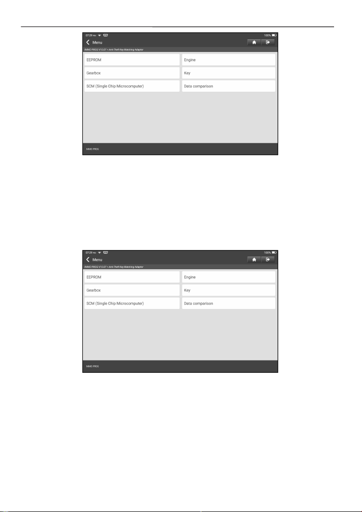
iSmartIMMO 801 User Manuall
16
3. Select the desired item to proceed.
5.2.1 EEPROM Programming
This function allows you to read/write on-board EEPROM chip data.
5.2.2 Engine Programming
This function allows you to read the engine data and write in the backup data
after a new engine is replaced.
Below procedures show you how to perform engine programming.
1. Tap Engine.
2. Select Engine Brand.
Table of contents
Other SmartSafe Test Equipment manuals

SmartSafe
SmartSafe iSmartEV EB480 User manual

SmartSafe
SmartSafe iSmartTool Series User manual

SmartSafe
SmartSafe iSmartEV ED500 User manual

SmartSafe
SmartSafe iSmartINC 605 User manual

SmartSafe
SmartSafe iSmartINC 402 User manual

SmartSafe
SmartSafe iSmartEV RT100 User manual

SmartSafe
SmartSafe iSmartEV OM210 User manual

SmartSafe
SmartSafe iSmartEV EB240 User manual

SmartSafe
SmartSafe iSmartIMMO G3 User manual


