MEERSTETTER LTR-1200 User manual

User Manual
LTR-1200
Valid for SN:006 to SN:XYZ
LDD / TEC 19” Rack Enclosure
Suitable for:
TEC-1089
LDD-1124
TEC-1090
LDD-1121
TEC-1122
LDD-1125
TEC-1123
Third-Party Devices
Meerstetter Engineering GmbH
Schulhausgasse 12
3113 Rubigen, Switzerland
Phone: +41 31 712 01 01
Email: contact@meerstetter.ch
Website: www.meerstetter.ch
Meerstetter Engineering GmbH (ME) reserves the right to make changes without further notice to the product described herein. Information
furnished by ME is believed to be accurate and reliable. However typical parameters can vary depending on the application and actual performance
may vary over time. All operating parameters must be validated by the customer under actual application conditions.
SWISS MADE


User Manual
LTR-1200
31.07.13 TB
22.10.14 SK
Page 3 (18)
5171C
Table of Content
1Device Overview 4
2Functional Description 5
2.1 Device-specific Documentation 5
2.2 Getting Started 5
2.3 Menu Structure 6
2.3.1 Available Device Parameter 7
2.4 Communication Interfaces 8
2.4.1 LTR-1200 Communication Concept 8
2.4.2 Connecting LTR-1200 over Ethernet 8
2.4.3 Service Software Default Address 9
2.4.4 Access over Third Party Software 9
2.4.5 Communication Fault Management 9
3Technical Data 10
3.1 Elements and Configurations 10
3.2 Front Panel 10
3.2.1 LCD 10
3.2.2 Navigation 10
3.2.3 LED 11
3.2.4 Digital I/O 11
3.2.5 RS485 12
3.2.6 RS232 12
3.2.7 USB 13
3.2.8 Ethernet 13
3.3 Back Panel 14
3.3.1 TEC Sensors Pinout 14
3.3.2 LDD Sensors Pinout 15
3.3.3 AC Mains Supply 16
3.4 Error Numbers 16
3.4.1 RTOS Errors 16
3.4.2 Routing Errors 16
3.4.3 HMI Errors 16
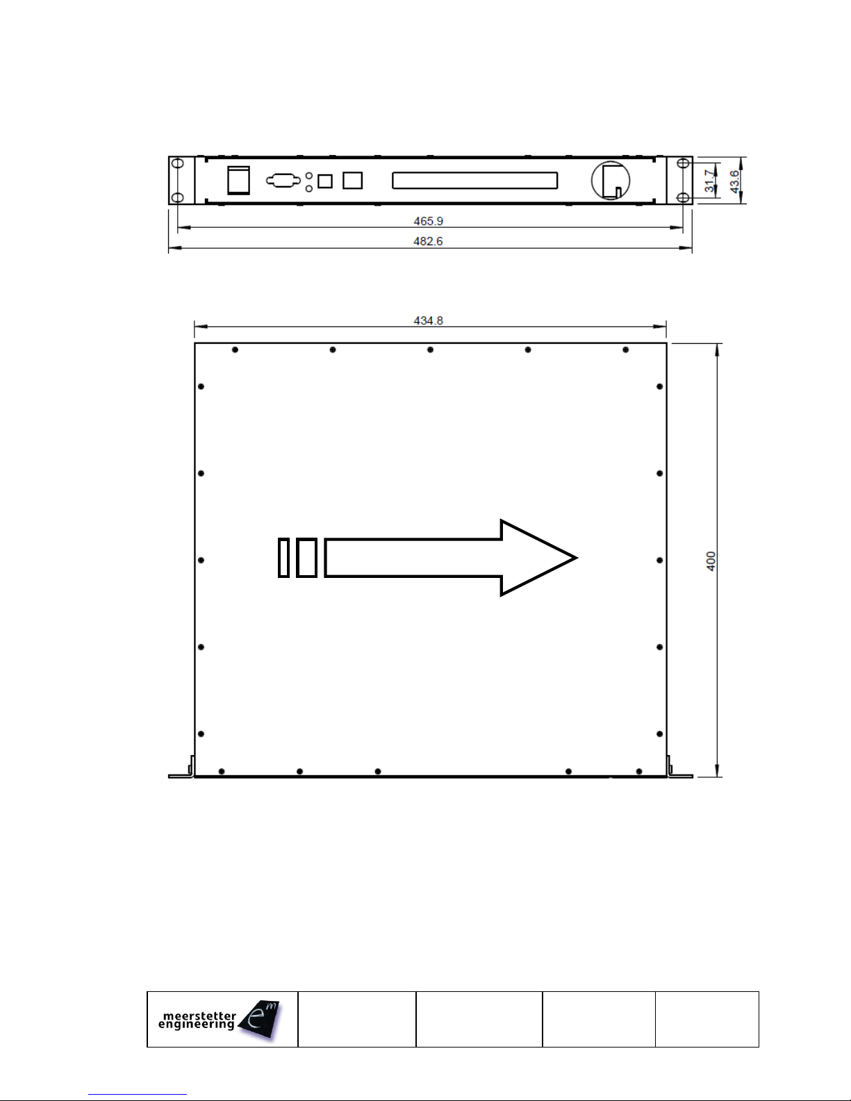
3.5 Physical Dimensions 17
3.6 License Notice 17
4Quotation Request Form 18
Page 4 (18)
5171
31.07.13 TB
22.10.14 TB
LTR-1200
User Manual
1 Device Overview
Features
General Description
Rack Enclosure Size:
1U, 400mm in Depth
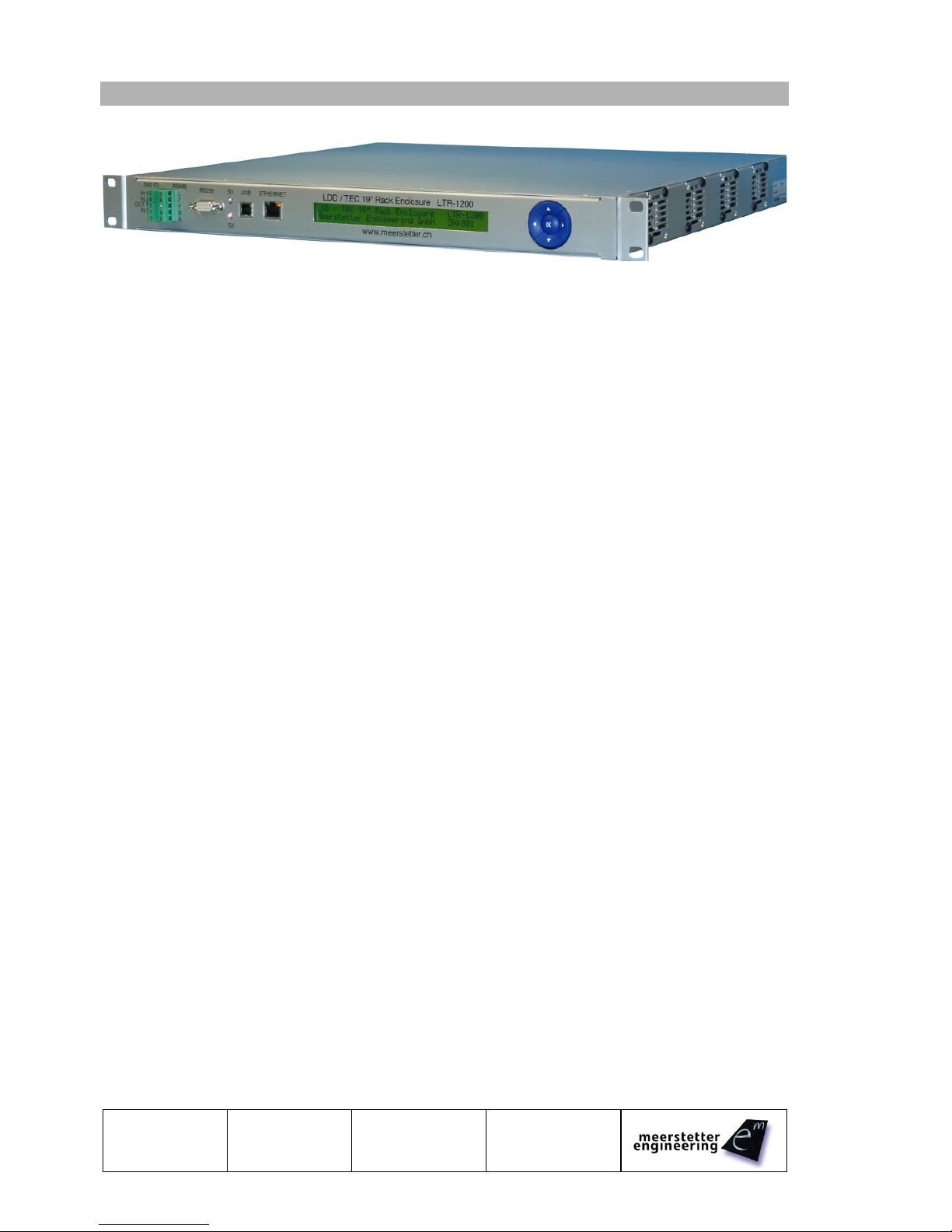
The LDD / TEC 19" rack enclosure LTR-1200 is a
highly configurable, ready-made carrier system
facilitating the integration of up to 4 devices
belonging to either the LDD-Family of laser diode
drivers or the TEC-Family of Peltier/TEC
controllers. The system caters for power, cooling
and communication.
The combination of built-in devices (models,
number) is freely selectable by the customer, their
application will dictate the choice (12V or 24V) and
number of internal primary DC power supplies.
Meerstetter Engineering will take care of the
integration and provide a fully configured turnkey
solution.
Up to 4 fans drag air sidewise through the rack
enclosure. Their speed is managed by intelligent
fan control on a dedicated PCB such that air-
cooling becomes effective upon prolonged use at
high ratings.
For table-top operation, the rack mounting brackets
can be removed.
The current status of the rack enclosure and of the
built-in devices are indicated on the front side
display (2x40 characters) and by dual color LEDs.
The most important settings (parameters of the
built-in devices and of the front side data interfaces)
can be adjusted over the 5-way navigation switch.
For advanced operation and configuration, all
internal devices can be addressed over one of the
electrically isolated interfaces; therefore the
originally supplied TEC and/or LDD Service
Software’s can be used.
For continuous monitoring and control by
customers' systems, the serial communication
protocol 'MeCom' can be used: on one hand, it
allows direct control of the each built-in LDD and
TEC device, on the other hand it allows polling
further information about the overall system status.
For fast signals (such as LDD pulse triggering)
three digital (electrically isolated) input lines are
available. Also, one digital output is available (e.g.
for error indication).
The integration of third party hardware (such as
fiber-coupled diode lasers) is possible if
dimensional requirements are met.
AC Input Voltage:
100..240V / 50..60Hz
Space for Devices:
Up to 4 LDD / TEC
Drivers; Third-Party
Devices (Max 8 Outputs)
Data Interfaces:
Electrically Isolated
(>1kV)
- Ethernet 10/100 MBit/s
- USB (Virtual Com Port)
- RS485
- RS232
Digital I/O Signals:
Electrically Isolated
(>1kV)
- 3 Digital Inputs
- 1 Digital Output
Human Machine
Interface (HMI):
Backlit 2x40 Character
Display and 5-Way
Navigation Switch for
Local Monitoring and
some Main Settings
Status Indication:
2 LED (Dual Color)
Forced Air Cooling:
Temperature-Dependent
Fan Speeds
Max Ambient
Temperature:
Full load up to 40°C
Half load up to 45°C
Advanced Operation
Remote Control:
LDD / TEC Service
Software and
'MeCom' Protocol
Applications
Optics (Laser Diodes, Crystals, …):
e.g. autonomous turn-key solutions for
comprehensive control (supply, cooling) of
ps lasers
Electronics (Detectors, RF References, …):
e.g. low-noise camera cooling
Instrumentation (Microscopy, Materials,
Biochemistry, …):
e.g. precision multi-temperature control
(thermal zones)

User Manual
LTR-1200
31.07.13 TB
22.10.14 SK
Page 5 (18)
5171C
2 Functional Description
2.1 Device-specific Documentation
The following devices can be installed into the LTR-1200. Some of these devices can be connected in
parallel to achieve higher output currents. Please contact Meerstetter Engineering if you have
requirements which currently are not covered by any of these devices.
LDD-Family (Laser Diode Drivers)
TEC-Family (Thermo Electric Cooling Controllers)
LDD-1121
LDD-1124
LDD-1125
TEC-1089
TEC-1090
TEC-1122
TEC-1123
The functional description and the technical data of these devices are documented in their own specific
Datasheets and User Manuals.
2.2 Getting Started
1. Connect the LTR-1200 to the mains power and switch it on.
The display shows the start screen
2. Wait until the LTR-1200 has finished startup.
The display now shows the main screen
No error is indicated (both LEDs are green)
3. Use the navigation switches to browse through the Menu. The Menu structure is documented in
chapter 2.3 Menu Structure
4. Connect to an internal device. (Chose one of the two options below):
(For more information about how to connect please refer to 2.4 Communication Interfaces)
Ethernet (preferred, if possible):
Remote Control over big distances.
Simultaneous connections (multiple applications) to several devices are possible.
Simultaneous connections (multiple PCs) to one device are possible.
oSet up the IP configuration (See chapter 2.4.2 Connecting LTR-1200 over
Ethernet)
oConnect the Ethernet cable.
USB:
Easy on-site connection.
Only one device at the same time.
oConnect the USB Cable.
5. Connect the corresponding (TEC or LDD) Service Software to a device
(Notice that you establish a connection to a device. “Device” and “Terminal” have different
meanings. See chapter 2.4.1 LTR-1200 Communication)
Set up the Service Software connection in the Maintenance Tab (See chapter 2.1
Device-specific Documentation)
When the Software is successfully connected it will show a green status “Connected” and
the Monitor tab will be updated periodically.
If you connect over Ethernet and wish to connect to multiple devices repeat this
procedure for all devices to connect.
6. Now the device(s) are connected. The device configuration and the various setting options are
described in the device-specific User Manuals. (See chapter 2.1 Device-specific Documentation)
Page 6 (18)
5171
31.07.13 TB
22.10.14 TB
LTR-1200
User Manual
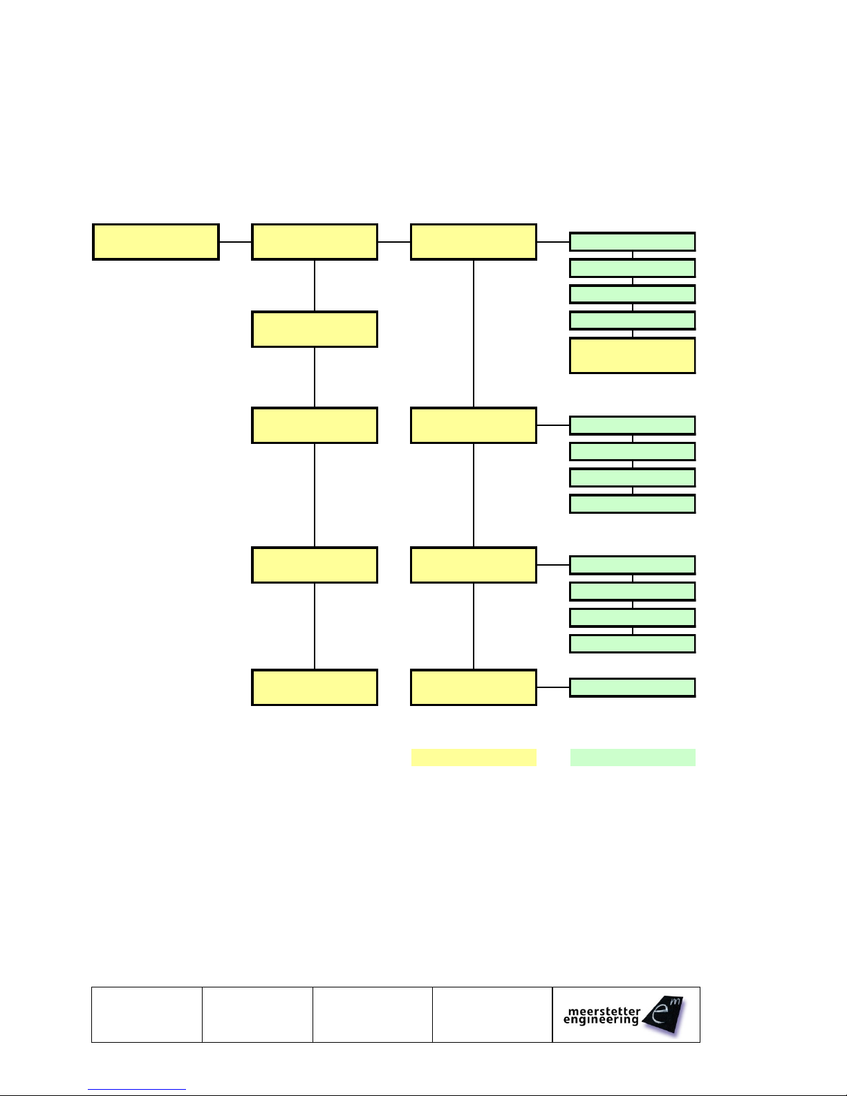
2.3 Menu Structure
The Menu is created dynamically depending on the installed devices. Only the Terminals to which a
device is connected are shown in the Menu. Each Terminal has its own Menu entry where the most
important settings of this Terminal can be adjusted. There is also a small overview for each Terminal.
Because there are so many parameters for each Terminal there is only a small selection of parameters
available through the display menu.
Below there is an example of the Menu structure with a TEC controller connected to Terminal 1 and an
LDD connected to Terminal 2.
Overview
T# 5-8
Manufacturer
Overview
LTR Settings &
IP Address
Type and S/N
T# 1-4
Device Status
IP Gateway
IP Network Mask
...
FANC Settings &
Device Status
T# 1 Detailed
T# 1 Settings &
Object Temperature
Device Overview
Device Status
Sink Temperature
Actual Output Current
...
T# 2 Detailed
T# 2 Settings &
Laser Diode I Act
Device Overview
Device Status
Laser Diode U Act.
Laser Diode Temp.
...
T# 3-8
T# 3-8 Settings &
...
Device Overview
Device Status
Legend:
T# -> Terminal
Status / Information
Settings
To navigate through the Menu use the 5-way navigation switch.
Settings marked with [-/R] have read only permissions.
Settings marked with [R/W] can be modified through the menu. Simply press the OK Button to switch to
the editing mode. Use left and right to switch between the digit positions. Use up and down to change the
digits value. Press OK to confirm the setting change.
Errors are shown on the overview screen with a symbol. For a description of the different Symbols see
3.2.1 LCD. A detailed Error Report will be shown on the device specific Menu screen.

User Manual
LTR-1200
31.07.13 TB
22.10.14 SK
Page 7 (18)
5171C
2.3.1 Available Device Parameter
Additional Parameters are available on request. Please contact Meerstetter Engineering for an inquiry.
2.3.1.1 LTR-1200
IPv4 Address
Gateway IPv4 Address
IPv4 Network Mask
Service Software Default Device
Interface RS232 Baud Rate
Interface RS485 Baud Rate
HMI Device Address
Internal Maximal Temperature
Internal Maximal Fan-Speed
2.3.1.2 LDD
Laser Diode Current Actual
Laser Diode Voltage Actual
Laser Diode Temperature
Laser Power Actual
Laser Diode Driver Enable
Laser Diode Current CW
Laser Diode Power CW
2.3.1.3 TEC
Object Temperature
Sink Temperature
Actual Output Current
Actual Output Voltage
Output Stage Enable
Target Object Temp
Page 8 (18)
5171
31.07.13 TB
22.10.14 TB
LTR-1200
User Manual
2.4 Communication Interfaces
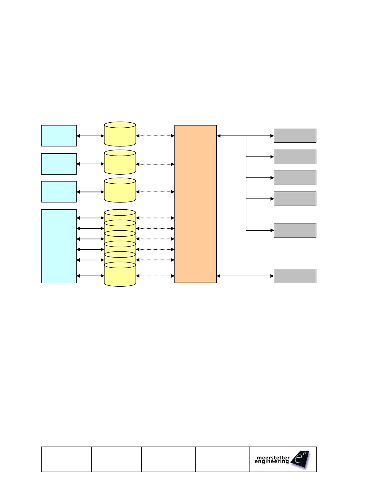
2.4.1 LTR-1200 Communication Concept
The LTR-1200 is equipped with several communication interfaces, which can be used simultaneously.
Every communication interface has its own receiving buffer.
The router will process every received message. The message is forwarded to the desired device. As
soon as the router task has received the responding message from the device, the message is forwarded
to the corresponding interface.
Every communication interface has the same priority. All messages are processed successively.
A connection is always between one control software and one device. The Terminal, device number and
Channel are not directly associated.
Terminal represents only the output on the Back-Plane of the LTR-1200. One device can be connected to
more than one Terminal.
Channel represents the output channel of one device (e.g. CH1 or CH2 in the case of TEC controllers.)
Please consult the “LTR-1200 Configuration Sheet” (which was supplied with the LTR-1200) to find out
which device channel is connected to which Terminal.
2.4.2 Connecting LTR-1200 over Ethernet
The LTR-1200 does not support DHCP. A fixed IP Address configuration must be set over the display
menu. Please set the following settings:
IP Address
Gateway Address (required for routing)
Network Mask
Please try to access to the built-in LTR-1200 web server by entering the previously configured IP Address
to your web browser.
Interface
Buffer
RS485
Interface
RS232
Interface
USB
Interface
Ethernet
Interface
Interface
Buffer
Interface
Buffer
Interface
Buffer
Router
TEC-1089
LDD-1121
TEC-1122
LDD-1125
HMI
FANC
LTR Internal BUS
Virtual Connection

User Manual
LTR-1200
31.07.13 TB
22.10.14 SK
Page 9 (18)
5171C
2.4.2.1 Ethernet Connection
Please refer to 2.1 Device-specific Documentation to connect the Service Software over Ethernet. The
Device Address (Device to be addressed) can be found on the LTR-1200 Menu or on the Built-in web
site. It usually is the same as the Terminal Number. The LTR-1200 provides a total of six connections
(TCP/IP, Port 50000, Timeout: 10s) to control the LDD/TEC Drivers over Ethernet. For Third Party
Software communication please refer to the MeCom communication protocol specifications (See chapter
2.1 Device-specific Documentation).
2.4.3 Service Software Default Address
In some cases it may be helpful to configure a default LDD/TED driver as standard device. This can be
done by setting the 'Service Software Default Device' parameter to a specific LDD/TEC Device Address in
the Display menu. In this case the Device Address 0 will be routed to the 'Service Software Default
Device'.
2.4.4 Access over Third Party Software
For Third Party Software communication please refer to the MeCom communication protocol
specifications (See chapter 2.1 Device-specific Documentation).
2.4.5 Communication Fault Management
2.4.5.1 For RS485, RS232 and USB Interfaces
A received MeCom-Package with a wrong CRC is not being processed, no error is generated.
If a MeCom-Package is being forwarded to a device (LDD/TEC) and no answer is received from the
device, no error is generated. The sending host must repeat the MeCom-Package.
2.4.5.2 For Ethernet Interface
A received MeCom-Package with a wrong CRC results in closing the corresponding TCP connection.
If a MeCom-Package is being forwarded to a device (LDD/TEC) and no answer is received from the
device, the MeCom-Package is being sent to the device two more times. If still no answer is received, the
TCP connection is closed by the LTR-1200.
Page 10 (18)
5171
31.07.13 TB
22.10.14 TB
LTR-1200
User Manual
3 Technical Data
3.1 Elements and Configurations
Each rack enclosure is equipped and configured to the customer's specifications:
Up to four LDD-Family or TEC-Family devices can be built in (See 4 Quotation Request Form).
The number of required power supplies and fans depends on types, numbers and applications of
the built-in devices. Meerstetter Engineering equips the LTR-1200 accordingly.
The LTR-1200 is back panel configurable, the standard panel offers 4 power output terminals and
4 sensors inputs connectors. (Up to 8 Terminals are possible)
It is also possible to install third party devices. Please contact Meerstetter Engineering with your
enquiry.
Important note concerning the integration of LDD-Family devices into LTR-1200 rack enclosures:
The internal wiring from an LDD device to its back panel terminal can measure several 10cm and
represents an inductive load. Therefore, fast pulsing performance will be impaired.
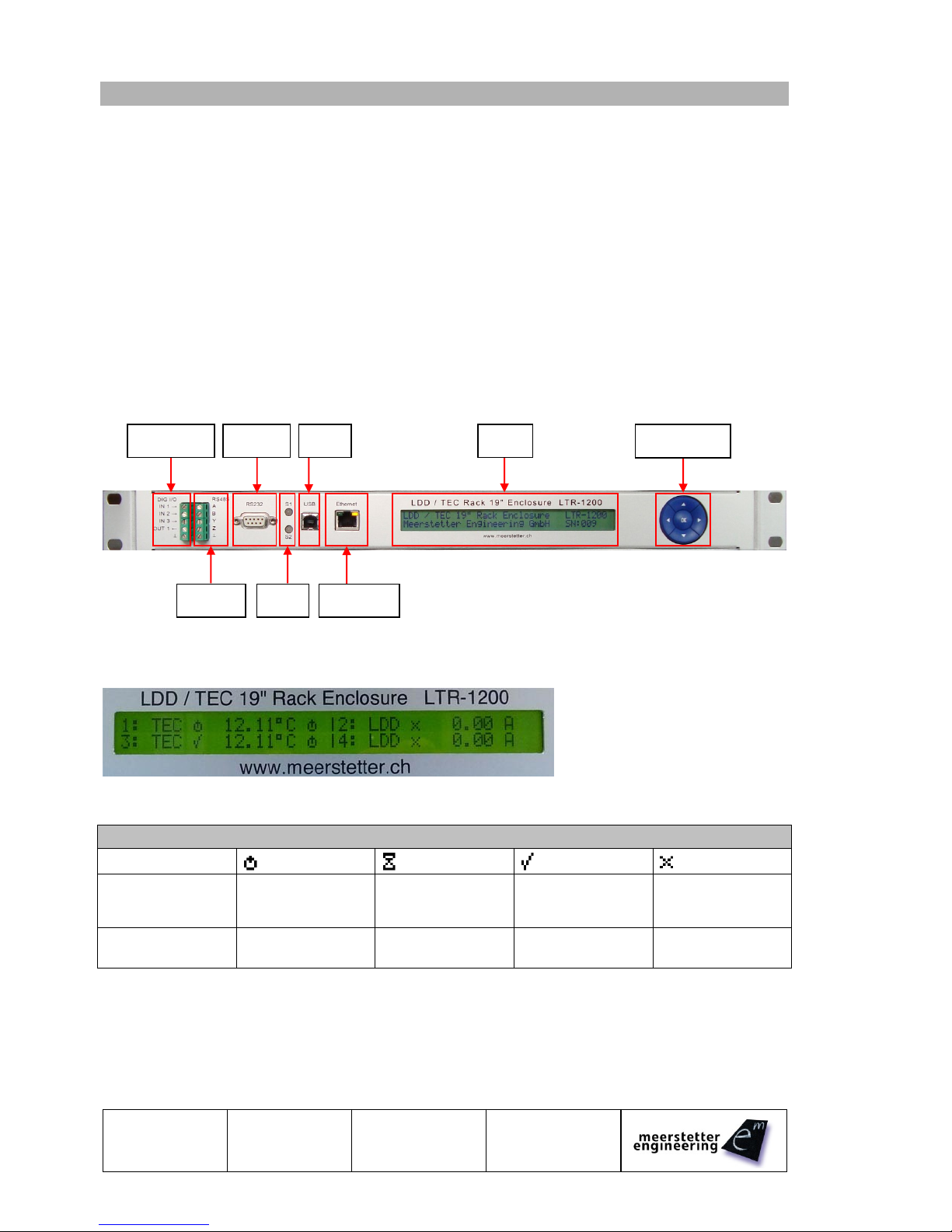
3.2 Front Panel
3.2.1 LCD
The picture shows the LCD display of an LTR-1200 with 4 devices built-in.
Symbols on the LCD Display
First Symbol
(next to TEC/LDD)
Device is 'Ready'
Other
(Reset, Restart,
Bootloader, …)
Device is 'Running'
Device has an
Error
Second Symbol
(if type is TEC)
Not in Temperature
Control Mode
'Wait'
(not stable, yet)
Stability Reached
-
3.2.2 Navigation
There is a five-point navigation switch available to browse through the Menu. This can be used to change
the most important settings of the internal devices.
Digital I/O
RS232
RS485
LED
USB
Ethernet
Navigation
LCD
User Manual
LTR-1200
31.07.13 TB
22.10.14 SK
Page 11 (18)
5171C
3.2.3 LED
Dual Color Status LEDs
LED
Sources (grouped)
S1 (top)
LTR Components (HMI, Fan Controller)
S2 (bottom)
Built-in Devices (LDDs, TECs)
Grouped status code is prioritized, i.e. if one output stage is running, the grouped LED shows 'Run', if one
device has an error, the grouped LED shows 'Error'.
LED Status Description (S1, S2)
Color
Pattern
Signification
Green
Slowly blinking
'Ready' status (no Error)
Green
Blinking fast
'Run' status (no Error)
Red
Static on
'Error' status, output stages disabled
Red
Slowly blinking
Unknown Device Status, but no Error
3.2.4 Digital I/O
3.2.4.1 Pinout
Type
DIG IO Label
LDD-112x
TEC-1122/1123
TEC-1089/1090
LTR-1200
Input 1
IN1
RES8
RES8
RES1
Special
Function
available
on request
Input 2
IN2
RES7
RES7
RES2
Input 3
IN3
RES6
RES6
RES3
Output 1
OUT
RES5
RES5
RES4
GND
Digital IO Ground
All digital I/Os are ESD-protected and have a series and pull-down resistor.
3.2.4.2 Characteristic
Symbol
Parameter
Comments
Min
Typ
Max
Units
Digital Isolator Characteristics
VISO
Isolation Voltage
1
-
2.5
kV
fTRANSFER
Transfer Frequency
NRZ (No Return to Zero)
0
25
MHz
tPHL, tPLH
Propagation Delay
45
60
ns
Input Characteristics (Digital Isolator)
VIH
Logic High Input Threshold
2.31
V
VIL
Logic Low Input Threshold
0.99
V
VIMAX
Max Input Voltage
-0.5
5.5
V
Output Characteristics (Digital Isolator)
VOH
Logic High Output Voltage
Output Current 20uA
3
3.3
V
VOL
Logic Low Output Voltage
Input Current 20uA
0
0.1
V
VOHL
Logic High Output Voltage (Hi Load)
Output Current 4mA
2.8
3.1
V
VOLL
Logic Low Output Voltage (Hi Load)
Input Current 4mA
0
0.4
V
ESD Protection (between Digital Isolator and Connector)
VPP
ESD Discharge
IEC61000−4−2
100
kV
RA
Series Resistance
170
200
230
Ω
Page 12 (18)
5171
31.07.13 TB
22.10.14 TB
LTR-1200
User Manual
3.2.5 RS485
3.2.5.1 Pinout
RS485 Label
Half-Duplex Connection
A
A
B
B
Y
Z
GND
3.2.5.2 Characteristic
Symbol
Parameter
Comments
Min
Typ
Max
Units
Digital Isolator Characteristics
VISO
Isolation Voltage
1
-
2.5
kV
Speed
Communication Speed (Baud Rate)
Software Setting
4800
1M
bps
VPP
ESD Protection
Human Body Model
+-15
kV
Input Characteristics (Receiver)
VTH
Differential Input Threshold Voltage
-200
-125
-30
mV
VHYS
Input Voltage Hysteresis
15
mV
RIN
Line Input Resistance
96
kΩ
Output Characteristics (Driver)
VOD1
Differential Output Voltage, Loaded
RL= 100Ω (RS422)
2.0
3.6
V
VOD2
Differential Output Voltage, Loaded
RL= 54Ω (RS485)
1.5
3.6
V
3.2.6 RS232
3.2.6.1 Pinout
Pin
Function
2
TxD (Data from LTR)
3
RxD (Data to LTR)
5
Signal Ground (GND)
other
Not Connected
3.2.6.2 Characteristic
Symbol
Parameter
Comments
Min
Typ
Max
Units
Protection Characteristics
VISO
Isolation Voltage
1
-
2.5
kV
VPP
ESD Protection
Human Body Model
+/-15
kV
Electrical Characteristics
Speed
Communication Speed (Baud Rate)
Software Setting
4800
1M
bps
VOH
High-level Output Voltage
TxD at RL= 3kΩ to GND
5
5.5
V
VOL
Low-level Output voltage
TxD at RL= 3kΩ to GND
-5
-5.4
V
VIT+
Positive Input Threshold Voltage
1.5
2.4
V
VIT-
Negative Input Threshold Voltage
0.6
1.2
V

User Manual
LTR-1200
31.07.13 TB
22.10.14 SK
Page 13 (18)
5171C
3.2.7 USB
The USB interface is electrically isolated. A virtual COM Port is provided for communication with a host
PC. The drivers are the same as the ones already required / installed for the individual internal devices.
(Used chip: FTDI FT232RQ)
3.2.7.1 Characteristic
Symbol
Parameter
Comments
Min
Typ
Max
Units
Protection Characteristics
VISO
Isolation Voltage
1
-
2.5
kV
VPP
ESD Protection
Human Body Model
+/-15
kV
Electrical Characteristics
Speed
Communication Speed (Baud Rate)
Software Setting
4800
1M
bps
3.2.8 Ethernet
3.2.8.1 Specifications
The Ethernet meets the following specifications:
IEEE 802.3 compliance
100BASE-TX and 10BASE-T compliance
Auto Negotiation (Automatically switch between 10Mbit/s / 100Mbit/s, Half -/ Full-Duplex)
Auto MDIX (Auto crossover)
Optional VLAN (available on request)
Optional IEEE 1588: Precision Time Protocol (available on request)
3.2.8.2 LED Description
Green
Orange
Off
Not connected
10Mbit/s
Blink
Activity
-
On
Connected
100Mbit/s
3.2.8.3 Available Features
Small embedded website
Service Software communication
MeCom protocol
Page 14 (18)
5171
31.07.13 TB
22.10.14 TB
LTR-1200
User Manual
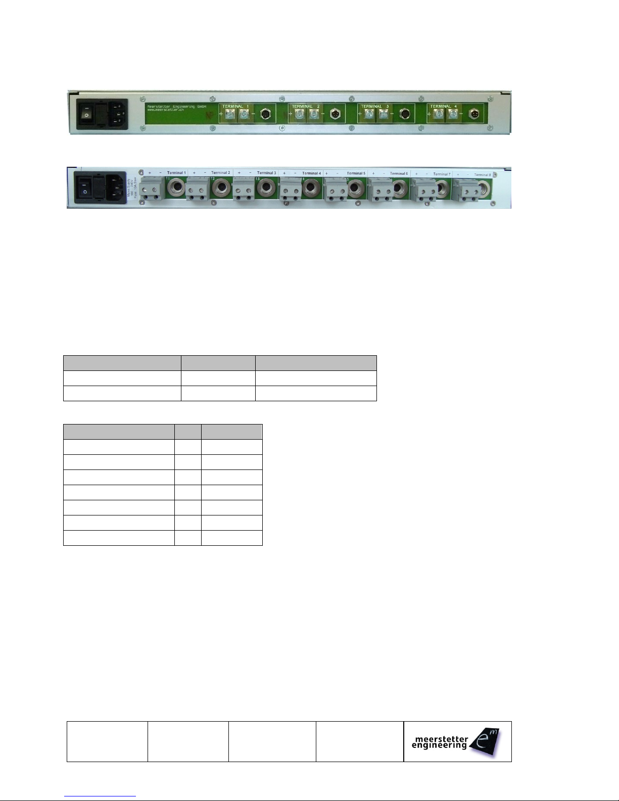
3.3 Back Panel
Picture of 4 Terminal Version. (Only approx, the Sensor connectors are wrong)
Picture of the 8 Terminal Version:
By standard, the GND potentials of all built-in TEC and LDD devices are interconnected. Consequently,
all external loads and sensors to be attached to the back panel should be potential-free. At the most, only
one single potential (e.g. GND of one laser diode) may be tied to a given potential; it is however
recommended to keep all loads and sensors potential-free.
Upon customer request, individual outputs can be equipped such that they are potential-free (i.e.
independent of other built-in devices). Please contact Meerstetter Engineering with your enquiry
3.3.1 TEC Sensors Pinout
Fully pre-confectioned cables are available from Meerstetter Engineering at request.
3.3.1.1 Part List
Description
Manufacturer
Manufacturer Part Nr.
Connector Solder 7-Way
Binder
99-4925-00-07
Cable 6-Way, Shielded
Kabeltronik
2-LifYCY TP (820600800)
3.3.1.2 Pinout
Function
Pin
Cable Color
Object Voltage Sense +
1
White
Object Voltage Sense -
2
Brown
Object Current Output
3
Green
Object Current Return
4
Yellow
Sink Sense A
5
Grey
Sink Sense B
6
Pink
NC
7
-
Please connect “Current Output” and “Voltage Sense +” together to one side of the thermistor,
and “Current Return” and “Voltage Sense –“ together to the other side of the thermistor.

User Manual
LTR-1200
31.07.13 TB
22.10.14 SK
Page 15 (18)
5171C
3.3.2 LDD Sensors Pinout
Fully pre-confectioned cables are available from Meerstetter Engineering at request.
3.3.2.1 Part List
Description
Manufacturer
Manufacturer Part Nr.
Connector Solder 4-Way
Binder
99-4909-00-04
Cable 4-Way, Shielded
Kabeltronik
2-LifYCY TP (820400800)
3.3.2.2 Pinout
Function
Pin
Cable Color
Temperature Sense A
1
White
Temperature Sense B
2
Brown
Photodiode Cathode
3
Green
Photodiode Anode
4
Yellow
Page 16 (18)
5171
31.07.13 TB
22.10.14 TB
LTR-1200
User Manual
3.3.3 AC Mains Supply
The main power connector is a 3-pol Connector for IEC C13 Cables
Symbol
Parameter
Comments
Min
Typ
Max
Units
Electrical Characteristics
VACnom
Nominal Input Voltage
Single Phase
100
240
V
VAC
Input Voltage
Continuous
90
264
V
VACtrans
Input Transients
60ms
300
V
fAC
Input Frequency
47
50/60
63
Hz
PIN
Input Power*
1 - 4 Power Supplies
400
1600*
W
PIN110
Input Power (110VAC)
1 - 4 Power Supplies
400
1100
W
Protection Characteristics
Fuse
Slow Fuse
Integrated into Connector
10
A
* When operated on 110VAC mains supply, the max input power is derated to 1100W due to the 10A fuse
built into the standard IEC C13 housing. Please contact Meerstetter Engineering if you require an
alternative connector.
3.4 Error Numbers
Error Numbers 1 to 99 are universal error numbers, which are identically on each device. For all other
universal error numbers please refer to the LDD-Family or TEC-Family User Manuals.
Error Numbers 100 and above are HMI (LTR)-specific.
3.4.1 RTOS Errors
#
Code
Description
Error Condition, Remedy
80
RTOS_STACKOVERFLOW
One task has a stack overflow
Please contact Meerstetter
Engineering
81
RTOS_MALLOCFAIL
Can not allocate memory
Please contact Meerstetter
Engineering
3.4.2 Routing Errors
#
Code
Description
Error Condition, Remedy
100
ROUTING_LOSTFRAME
The routing task has lost a
frame
Lost frame on internal bus
101
COM_TIMEOUT
Communication timeout to an
internal device occurred
No answer for 3x100 ms
102
ADDRESS_CONFLICT
Two internal devices use the
same address on the bus
Two identically addresses
detected
3.4.3 HMI Errors
#
Code
Description
Error Condition, Remedy
110
DEVICE_VERSION
HMI and device firmware
versions not compatible
Update all device firmware to
the actual version.
111
DEVICE_MISSING
Unassigned rack output
terminal detected
Try to reboot the LTR-1200
112
MENU_OWERFLOW
Menu memory overflow
Please contact Meerstetter
Engineering
113
UNKNOWN_DEVICE
Unknown internal device
recognized
Please contact Meerstetter
Engineering
User Manual
LTR-1200
31.07.13 TB
22.10.14 SK
Page 17 (18)
5171C
3.5 Physical Dimensions
All dimensions are in mm
Rack mounting brackets are removable
3.6 License Notice
The LTR-1200 Software is built on FreeRTOS (http://www.freertos.org).
Air-Flow
Page 18 (18)
5171
31.07.13 TB
22.10.14 TB
LTR-1200
User Manual
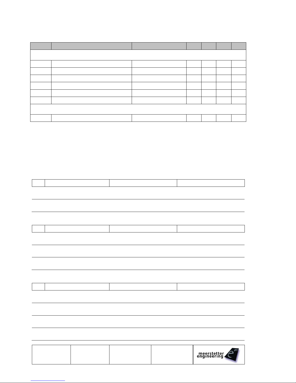
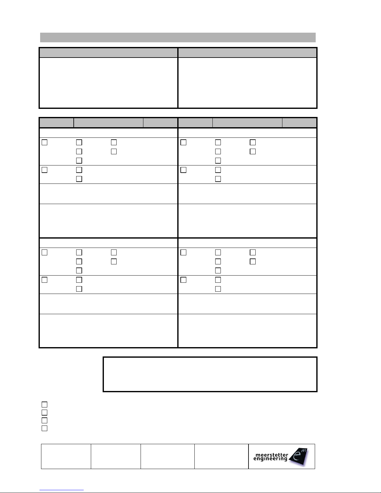
4 Quotation Request Form
Contact Information (Address)
Please Describe your Application
Type
Sensor Type
Power
Type
Sensor Type
Power
Output 1
Output 2
TEC
PT100
4 Wire
_____A
TEC
PT100
4 Wire
_____A
PT1000
2 Wire
_____V
PT1000
2 Wire
_____V
NTC
NTC
LDD
No LPC
_____A
LDD
No LPC
_____A
LPC
_____mA
_____V
LPC
_____mA
_____V
Laser Diode / Peltier Module (Manufacturer; Model)
Laser Diode / Peltier Module (Manufacturer; Model)
Comments / Special Requirements
Comments / Special Requirements
Output 3
Output 4
TEC
PT100
4 Wire
_____A
TEC
PT100
4 Wire
_____A
PT1000
2 Wire
_____V
PT1000
2 Wire
_____V
NTC
NTC
LDD
No LPC
_____A
LDD
No LPC
_____A
LPC
_____mA
_____V
LPC
_____mA
_____V
Laser Diode / Peltier Module (Manufacturer; Model)
Laser Diode / Peltier Module (Manufacturer; Model)
Comments / Special Requirements
Comments / Special Requirements
Special Requirements:
More than 4 Outputs are needed (up to 8 TEC outputs are possible)
The TEC outputs need to be independent. (If an Error occurs on one output, the others continue)
Pre-confectioned Sensor Cables are required. Cable Length: _____m
Third-party devices need to be installed: Please send us more information about this device
Table of contents
Popular Enclosure manuals by other brands

SilverStone
SilverStone Lascala LC11 manual

ZALMAN
ZALMAN Z5 U3 user guide

Macpower & Tytech
Macpower & Tytech Hydra S2 user manual

BE QUIET!
BE QUIET! SILENT BASE 801 user manual

HP
HP 418800-B21 - StorageWorks Modular Smart Array 70 Storage... Maintenance and service guide

Allen-Bradley
Allen-Bradley 198E-A0S Series Application Instruction


Dynex
Dynex DX-HD302513 Guía De Instalación Rápida

Agilent Technologies
Agilent Technologies G6012A User information

Extron electronics
Extron electronics PowerCage 411 Series user guide

Avid Technology
Avid Technology Unity LANshare LP Replacement procedure

Rosewill
Rosewill SPECTRA D100 Quick user guide

Rittal
Rittal SK 3185.330 Assembly and operating instructions