manuals.online logo
Brands
  1. Home
  2. •
  3. Brands
  4. •
  5. Allen-Bradley
  6. •
  7. Enclosure
  8. •
  9. Allen-Bradley 198E-A0S Series User guide

Allen-Bradley 198E-A0S Series User guide

This manual suits for next models

1

Other Allen-Bradley Enclosure manuals

Allen-Bradley 198E-A0S Series User guide

Allen-Bradley

Allen-Bradley 198E-A0S Series User guide

Allen-Bradley 22-JBCB User manual

Allen-Bradley

Allen-Bradley 22-JBCB User manual

Allen-Bradley 198E-C0C4R User guide

Allen-Bradley

Allen-Bradley 198E-C0C4R User guide

Allen-Bradley CENTERLINE 200 A User manual

Allen-Bradley

Allen-Bradley CENTERLINE 200 A User manual

Allen-Bradley SK-M1-CVR0-B4 User manual

Allen-Bradley

Allen-Bradley SK-M1-CVR0-B4 User manual

Allen-Bradley 1336 PLUS II User manual

Allen-Bradley

Allen-Bradley 1336 PLUS II User manual

Allen-Bradley 198E-C0S4R User guide

Allen-Bradley

Allen-Bradley 198E-C0S4R User guide

Allen-Bradley PowerFlex Active Front End User manual

Allen-Bradley

Allen-Bradley PowerFlex Active Front End User manual

Popular Enclosure manuals by other brands

Antec Veris Fusion Remote Max Specification sheet

Antec

Antec Veris Fusion Remote Max Specification sheet

ENERMAX iVektor.Q ECA 3371 Series user manual

ENERMAX

ENERMAX iVektor.Q ECA 3371 Series user manual

Lindy 43095 user manual

Lindy

Lindy 43095 user manual

SICK C4000 Select operating instructions

SICK

SICK C4000 Select operating instructions

Geeek A60 PLUS installation guide

Geeek

Geeek A60 PLUS installation guide

OVE SYDNEY 48 installation manual

OVE

OVE SYDNEY 48 installation manual

SilentiumPC Armis AR5 Hardware installation

SilentiumPC

SilentiumPC Armis AR5 Hardware installation

Pulsar 17/TRP80/DSPR Assembly instructions

Pulsar

Pulsar 17/TRP80/DSPR Assembly instructions

MSI MPG SEKIRA 500X quick start guide

MSI

MSI MPG SEKIRA 500X quick start guide

Antec Dark fleet DF-10 user manual

Antec

Antec Dark fleet DF-10 user manual

Peavey DS 1502 Specifications

Peavey

Peavey DS 1502 Specifications

D-Link ShareCenter Pro DNS-1550-04 user manual

D-Link

D-Link ShareCenter Pro DNS-1550-04 user manual

Rosewill RX82-U(JBOD) user manual

Rosewill

Rosewill RX82-U(JBOD) user manual

QNAP SAS JBOD CLI 1.0 user guide

QNAP

QNAP SAS JBOD CLI 1.0 user guide

GAMDIAS Talos P1 Quick installation guide

GAMDIAS

GAMDIAS Talos P1 Quick installation guide

Auvs KR615 user manual

Auvs

Auvs KR615 user manual

Antec AR300 user manual

Antec

Antec AR300 user manual

CommScope FDH 3000 user manual

CommScope

CommScope FDH 3000 user manual

manuals.online logo
manuals.online logoBrands
  • About & Mission
  • Contact us
  • Privacy Policy
  • Terms and Conditions

Copyright 2025 Manuals.Online. All Rights Reserved.

198E-A0S..
198E-C0S..
198E-A0S.. 198E-C0S..
Plastic Enclosures for DOL-Starters - Application Instruction
Kunststoffgehäuse für DOL-Starter - Anwendungsanweisung
Boîtiers plastiques pour démarreurs direct - Notice d´application
Custodie plasitce per avviatori diretto - Istruzione d'applicazione
Cofres em plástico para arrancadores directo - Instrucción d'applicazione
WARNING: To prevent electrical shock, disconnect from power
source before installing or servicing. To be commissioned and
maintained only by qualified personnel; pay attention to the
operating instructions!
WARNUNG: Vor Installations- oder Servicearbeiten
Stromversorgung unterbrechen, um Unfälle zu vermeiden.
Inbetriebsetzung und Wartung nur durch Fachpersonal;
Betriebsanleitung beachten!
AVERTISSEMENT: Avant le montage et la mise en service, couper
l'alimentation secteur afin d'éviter tout accident. Mise en
service et entretien: seulement par du personnel spécialisé;
respecter les instructions d'exploitation!
AVVERTENZA: Per prevenire infortuni, togliere tensione prima
dell'installazione o manutenzione. Messa in servizio e
manutenzione solo da personale specializzato; attenersi alle
istruzioni per l'esercizio!
ADVERTENCIA: Desconectar la alimentación eléctrica antes de
realizar el montaje y la puesta en servico, con el objeto de
evitar accidentes. Puesta
en servicio y mantenimiento
exclusivamente por personal especializado; respetar las
instrucciones de puesta en servicio y mantenimiento!
EN / IEC 62208
EN / IEC 60947-4-1
UL 50
UL 508
CSA 22.2, No. 14
EN / IEC 62208
EN / IEC 60947-4-1
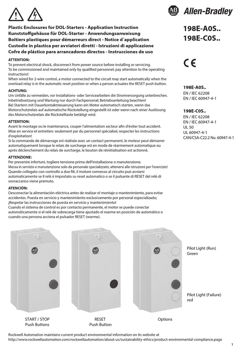
Pilot Light (Run)
Green
Pilot Light (Failure)
red
START / STOP
Push Buttons
RESET Push Button
Options
2
198E-A0S4 / -C0S4 with START / STOP Push Buttons
123
45
198E-A0S1 / -C0S1 with RESET Push Button
Accessories
Push button latch for maintained control
Drucktasten-Verklinkung für
Dauerkontakt-Steuerung
Accrochage des bouton-poussoirs pour
commande de contact permanent
Ritenuta di pulsante per comando a
contatto permanente
Retención de pulsador para mando a
contacto permanente
Neutral Terminal
Neutralleiterklemme
Borne de neutre
Morsetto di neutro
Borna de neutro
Pilot Lights
Meldeleuchten
Voyants lumineux
Lampade spia
Lámparas de señalización
140-L...
(Not for UL or CSA applications)
Pilot Lights
Meldeleuchten
Voyants lumineux
Lampade spia
Lámparas de señalización
800FD-P...
198E-PLA
198E-PNT
USA + Canada:
Use 800F Pilot Lights only
Dimensions
Wiring Diagrams
205
[8.08]
44.5
[1.75]
19.5
[0.77]
188
[7.41]
Ø5.3
[Ø0.21]
51
[2.01]
Ø20.3
[Ø0.80]
23.7
[0.94]
188
[7.41]
23.8
[0.94]
31.5
[1.24]
25.2
[0.99]
111
[4.37]
5.5
[0.22]
Ø25.3
[Ø1.00]
111
[4.37]
5.5
[0.22]
207.9
[8.19]
97.9
[3.86]
68
[2.68]
60.3
[2.38]
36.5
[1.44]
36.5
[1.44]
Center Marks Inside
Pilot Lights: - 140-L*: IP 54
-800FD:IP66
10
2x1...6mm²
2 x No. 14...10 AWG
Pozidriv No. 2
2.3 Nm
20 lb-in
Pozidriv No. 2
2.0 Nm
18 lb-in
(1.2 x 6.5)
188 mm Ø 5.3
7.4" 0.2" DIA
3
4
4
3
Removed when 198E-PLA installed
3
Added wires for common control. Remove if separate control is required.
4
L1 Control voltage supplied from external source.
5
5
5
5
5
5
L1
1
96
95
97
98
L1
I
I
3
2
1
1- HAND
2- OFF
3- AUTO
A1
A2
2 WIRE
CONTROL
1 When E-STOP is used
Illuminated HOA Selector Switch
WARNING:
Bonding between metallic conduits must be provided.
AVERTISSEMENT:
Une liaison électrique doit être assurée entre les conduits
métalliques.
WARNING:
The opening of the branch circuit protective device may
be an indication that a fault current has been interrupted.
To reduce the risk of re or electric shock, current-carrying parts and
other components of the controller should be examined and replaced
if damaged.
WARNING: With the mechanical latch ( ) installed or when wired for
2-wire control, a motor connected to the circuit may start automatically
when the overload relay is in the automatic reset position.
DIR 10000389627 (Version 02)
Printed in Spain
3-phase Motors
230V 50Hz 400V 50Hz 500V 50Hz 690V 50Hz 200V 60Hz 230V 60Hz 460V 60Hz 575V 60Hz 100kA, 690V 100kA, 600V
Contactor
1)
Overload
Relay
2)
Min
A
Max
AkW kW kW kW HP HP HP HP
DIN Fuses
Type gL/gG
Max. Fuse
Class CC, J
100-C09*10 193-ED1AB 0.10 0.50 0.06…0.09 0.06...0.12 0.06...0.12 0.06...0.18 -- -- -- -- 23
100-C09*10 193-ED1BB 0.20 1.0 0.12 0.18...0.25 0.18…0.37 0.25…0.55 -- -- 1/4…1/3 1/4...'1/2 44
100-C09*10 193-ED1CB 1.0 5.0 0.18…1.1 0.37…1.5 0.55…2.2 0.75…3 1/4…3/4 1/4…1 1/2...2 3/4…3 16 10
100-C09*10 193-ED1DB 3.2 16 1.5…3 2.2…4 3.0…4 4 1…2 1 1/2...2 3…5 5...7 1/2 20 15
100-C12*10 193-ED1DB 3.2 16 4 5.5 5.5 5.5 3 3 7 1/2 10 25 20
100-C16*10 193-ED1DB 3.2 16 7.5 7.5 7.5 33
71/2 10 32 30
100-C16*10 193-ED1EB 5.7 51
0
1
5
55.
5
7
235 45
100-C23*10 193-ED1EB 5.7 27 7.5 10…11 10…13 10 571/2 15 15 40 45
100-C09*10 193-T1AA16 0.10 60
.06
1
.0 -- -- -- -- 21
100-C09*10 193-T1AA25 0.16 0.25 0.06 0.06 0.09 -- -- -- -- 21
100-C09*10 193-T1AA40 0.25 0.40 0.09 0.09...0.12 0.12…0.18 -- -- -- -- 21
100-C09*10 193-T1AA50 0.35 0.50 0.06 0.12 -- -- -- -- 42
100-C09*10 193-T1AA63 0.45 0.63 0.09 0.18 0.25 -- -- -- 1/4 43
100-C09*10 193-T1AA80 0.55 0.80 0.12 0.18 0.25 0.37 -- -- 1/4…1/3 1/3 43
100-C09*10 193-T1AB10 0.75 1.00 0.25 0.37 0.55 -- -- 1/3 1/2 64
100-C09*10 193-T1AB13 0.90 1.30 0.18 0.37 0.75 -- 1/4 1/2 64
100-C09*10 193-T1AB16 1.10 1.6 0.25 0.55 1/4 1/3 3/4 3/4 64
100-C09*10 193-T1AB20 1.40 2.0 0.75 0.75 1.1 1/3 1/3 3/4...1 1 64
100-C09*10 193-T1AB25 1.80 2.5 0.37 1.1 1.5 1/2 1 1/2 10 6
100-C09*10 193-T1AB32 2.3 3.2 0.55 1.1 1.5 2.2 1/2 3/4 11/2 2 10 6
100-C09*10 193-T1AB40 2.9 24
/3
4
/
3
5
.
1
57
.00
.4 310 10
100-C09*10 193-T1AB48 3.5 331
1
32.
28.
410 10
100-C09*10 193-T1AB63 4.5 6.3 1.1 2.2 3 4 11/2 11/2 516 12
100-C09*10 193-T1AB75 5.5 7.5 1.5 3 4 1 1/2…2 2 5 5 16 15
100-C09*10 193-T1AC10 7.2 10.0 2.2 4 271/2 20 20
100-C09*10 193-T1AC12 9.00 12.5 3 25 20
100-C12*10 193-T1AB75 5.5 5.
5
5.7 16 15
100-C12*10 193-T1AC10 7.2 5.
50
.01 20 20
100-C12*10 193-T1AC12 9.00 01
2
/17335.55.21 25 20
100-C16*10 193-T1AC10 7.2 5
.70
.
01 20 20
100-C16*10 193-T1AC12 9.00 12.5 7.5 25 20
100-C16*10 193-T1AC16 11.3 01
55.75.7
4
0.61 32 30
100-C16*10 193-T1AC20 15.0 5150.02 32 30
100-C23*10 193-T1AC16 11.3 0
1
0.61 32 30
100-C23*10 193-T1AC20 15.0 1
1
0.02 40 35
100-C23*10 193-T1AC21 17.50 51
3
15.5
5
.
1
240 35
100-C23*10 193-T1AC25 21.00 2/17110.5
240 40
Single-phase Motors
230V 50Hz 115V 60Hz 200V 60Hz 230V 60Hz 100kA, 690V 100kA, 600V
Contactor
1)
Overload
Relay
2)
Min
A
Max
AkW HP HP HP
DIN Fuses
Type gL/gG
Max. Fuse
Class CC, J
100-C09*10 193S-EEPB 1.0 5.0 0.12…0.55 1/10…1/6 1/6…1/3 1/6…1/3 16 10
100-C09*10 193S-EERB 3.2 16 0.75…1.5 1/4…1/2 1/2…1 1/2 1/2…1 1/2 20 20
100-C12*10 193S-EERB 3.2 16 2.2 1/2 22
25 25
100-C16*10 193S-EERB 3.2 16 2.2 3/4 22
32 25
100-C16*10 193S-EESB 5.4 27 3.0 1 2335 30
100-C23*10 193S-EESB 5.4 27 4.0 1 1/2...2 3 340 40
100-C09*10 193-T1AA16 0.10 0.16 -- -- -- -- 21
100-C09*10 193-T1AA25 0.16 0.25 -- -- -- -- 21
100-C09*10 193-T1AA40 0.25 0.40 -- -- -- -- 21
100-C09*10 193-T1AA50 0.35 0.50 -- -- -- -- 42
100-C09*10 193-T1AA63 0.45 0.63 -- -- -- -- 43
100-C09*10 193-T1AA80 0.55 0.80 0.06 -- -- -- 43
100-C09*10 193-T1AB10 0.75 1.0 0.09 -- -- -- 64
100-C09*10 193-T1AB13 0.90 1.3 0.12 -- -- -- 64
100-C09*10 193-T1AB16 1.1 1.6 0.12 -- -- -- 66
100-C09*10 193-T1AB20 1.4 2.0 0.18 -- -- -- 66
100-C09*10 193-T1AB25 1.8 2.5 0.25 -- -- 1/6 10 10
100-C09*10 193-T1AB32 2.3 3.2 0.37 1/10 1/6 1/4 10 10
100-C09*10 193-T1AB40 2.9 4.0 0.37 1/8 1/4 1/3 10 10
100-C09*10 193-T1AB48 3.5 4.8 0.55 1/6 1/3 1/3 10 10
100-C09*10 193-T1AB63 4.5 6.3 0.75 1/4 1/2 1/2 16 15
100-C09*10 193-T1AB75 5.5 7.5 1.1 1/3 3/4 16 15
100-C09*10 193-T1AC10 7.2 10.0 1.1 1/3 3/4…1 1 20 20
100-C09*10 193-T1AC12 9.0 12.5 1.5 1/2 1 1/2 1 1/2 25 20
100-C16*10 193-T1AC16 11.3 16.0 2.2 3/4 2 2 32 30
100-C16*10 193-T1AC20 15.0 3
130.02 32 30
100-C23*10 193-T1AC21 17.5 21.5 311/2 3 40 35
100-C23*10 193-T1AC25 21.0 25.0 2 40 35
Components
Current Range
Components
Current Range
1)
Contactors
To complete the Catalog No.,
replace * by the coil voltage code
2)
Overload Relays
193-ED1*: Electronic overload relays
(193-EE* can be used as well).
193S-EE*: Electronic overload relays
specially for single-phase motors
Max. environmental temperature 40 °C
(outside the enclosure)
193-T1*: Thermal overload relays.
Max. environmental temperature 40 °C
(outside the enclosure)
Component Selection for Enclosed Starters