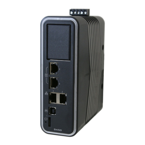
Mega Electronics EXPANDER GSM NV3.3T User manual

EXPANDER GSM NV3.3 T manual www.megaelektronik.pl page 1
EXPANDER GSM NV3.3T
GSM noticing module
Function of alarm central unit
Remotely controlled GSM
GSM ug
Thermostat GSM
NV3.3T Cooperates with Nokia NOKIA
Nokia 5110/5130/6130/6150/3330/3410

EXPANDER GSM NV3.3 T manual www.megaelektronik.pl page 2
Warnings!
Exact study of this instruction will provide proper and safe
usage of the device. It is not allowed to conduct any
repairs or modifications. Due to safety reasons installation
should take place only by qualified personnel. This device
is a source of electromagnetic waves, thus in specific
configurations may cause distortion in proper work of
other radio devices.
Fulfills directive EU, WEEE
According to the assumptions of directive EU, WEEE, electrical devices must be
handed over to local waste assembly point. Our company provided, for our clients to
whom we delivered new device, collecting and transportation service of old devices
produced by our company and delivering it to the sorting and utilizing facility. After
accommodating new device, our clients have a right to receive a document certifying
utilization of the old product. This action corresponds to all products that are provided
as a ready to use product as well as elements that are individual parts of our solutions.
In case of conducting work, all materials said to be hazardous and following the
assumptions of directive WEEE that are exchanged by devices and elements installed
by our company are collected during the process and handed over to a proper
assembly point free of charge.

EXPANDER GSM NV3.3 T manual www.megaelektronik.pl page 3
Characteristic
Expander GSM NV3.3T after connecting to and external mobile phone NOKIA 110, 130,
6130, 61 0, 3330, 3410 enables:
-cooperation with every mobile phone network
-efficiency and reliability as well as simple handling
-quick assembly and start up
-connection to all alarm systems
-construction of local GSM W-LAN RESTARTER system, SERWER
-construction of local alarm system, function of alarm central unit
-cooperation with all types of sensor.
-standalone diagnostics of connected phone. Turning on and entering PIN code
-remote reading of inputs and outputs
-remote change of outputs states
-remote temperature reading
-two independent thermostats range - 0C up to +12 C with GMS noticing function
-wire tap in GSM networks
-cooperation with speech synthesizer
-controls correctness of temperature sensors functioning
- independent high voltage remote control canals via GSM network
Functioning of GSM module is determined by means of rogramming it and connected signals, of
which state it is su osed to inform or control. Module rogramming takes lace by entering
articular entries on SIM card, which is laced in the hone connected to the module. All
configurations are saved in non-volatile SIM card memory, which can be restored even after ower
su ly failure and after module ower su ly is turned on it starts u the hone and loads the
reviously stored configuration. Calling time is constant and equal to 25sec.
Connected hone works without batteries or charger.
Destination
•
Alarm systems for mechanical and floating vehicles and objects
•
Power su ly su ervision, control and correct functioning systems of devices used to
transfer data or other media
•
Su ervision, measurement and regulation of tem erature
•
Where it is necessary to maintain high security and control level combined with effortless
and sim le handling
Functions
Method of arming the module
Module can be armed or disarmed
• Via SMS secured by access code from any mobile hone
• Via ring tone signal from authorized number
•Arming can also be erformed by means of additional external devices ie. radio line or
hidden switch (using ARM out ut)
Additional reaction on arming a module via line IN-A can be:
•Turned on out ut OUT –S for a remote time 1 u to 99999 sec after arming the module and
setting u the delay after which OUT –S should turn on after arming the module from the
range 1 u to 999999sec.
Arming and disarming function can be broadened by acknowledgement of correctly erformed
o eration via SMS.

EXPANDER GSM NV3.3 T manual www.megaelektronik.pl page
Example of arming and disarming line IN-A
Configuration of Input lines
In order to revent excessive utilization costs, es ecially false alarms, the device contains a set of
ossibilities of rogramming and alarm in ut analysis. Any device in ut can be configured as
normally o ened or normally closed. It means, that in a state set for in ut NO, active state will be
short-circuit to + of ower su ly or bulk of the module thus in a set state for in ut NC, active
state will be o en-circuit to + of ower su ly or bulk of the module. Besides the method of
setting u in ut lines, it is ossible to declare the time, after which change of state can be
conceded as a violation of 1 u to 999999sec. Additionally it can be set, which of the lines should
be two-stated, meaning reacting to agitation state as well as non–agitation state. Maintaining
active signal on in ut for a longer eriod of time than minimal results only in a single alarming.
Next in ut realize is ossible after agitation signal disa ears. All in uts react only to changes of
state so alarming will take lace only if there will be active signal on the in ut and it will maintain
for rogrammed eriod of time. In order to have active lines, module must be armed.
Example of connecting input lines
Reaction to input lines agitation
Module can send different reaction to every user (in given order)
•SMS
•Ring
•SMS + Ring
•Ring + SMS
•Turn on out ut OUT S for a set time
Calling time is constant and equal to 25sec. Module check the correctness of receiving signal
Remote control function
Module out uts OUT 1 i OUT 2 can be turned on or off via SMS on remote time from range
1 u to 999999sec or turned on or off ermanently.
This o eration, as in case of remote arming, requires entering access code.
Remote control function can be enchanted by a re ort of executed o eration, which is send back to
the number, which send a SMS with a command to change out ut status. Out uts are of
transmitting ty e 10A/230V with change-over contact.

EXPANDER GSM NV3.3 T manual www.megaelektronik.pl page 5
Report function –exacted test
Module can be remotely „asked” about it’s status via SMS. In res onse, module will send a SMS
and in this way one can get information about current status: armed/disarmed and in uts and
out uts, number of currently connected sensors and current tem erature. Re ort is send to a
number from which such request was send. This o eration, as in case of remote arming, requires
entering access code.
Bug function
Module will receive connections from authorized numbers and maintain them as long as the caller
won’t terminate connection. Thanks to that bug from micro hone located in the hone connected
to the module or other connected device is ossible (in ut MC) Connections to unauthorized users
will automatically be rejected.
ECHO function
Module will automatically receive „foreign” incoming SMS and forward them to authorized users.
Thanks to that function it is very easy to detect any attem ts of attack by unauthorized eo le or
one can receive information from GSM network in which the device is working.
Temperature measurement function
If tem erature sensors have been connected to the module Je CT-1 (max.2units) there are
available such ossibilities:
Noticing about exceeding set tem erature..
Turning on or off out uts de ending on set tem erature. Each change of tem erature besides set
range or turning on or off o erations of articular out ut connected to a sensor can be also
confirmed via SMS on authorized numbers. Module checks if connected tem erature sensors work
ro erly and in case of any roblems notices about them via automatically generated status
re orts
Back-up power supply system
In case of ower loss, module contains back-u ower su ly system.
The source of su ly is a 9V battery or other 7.5V...15V voltage source
Standby time on new battery is a rox. four hours. This value can be less if at a articular moment
ie. high voltage out uts or other devices are turned on.
V-BAT in ut is used to connect backu ower su ly ie. 9V battery
Diagnostics of connected phone
Device checks correct work of connected GSM hone at all the time and maintains it in turn on and
logged on to GSM network state Connected GSM hone works without battery or external charger.
While starting u the module, hone is automatically turned on and PIN code is given.
Power saving and work at low temperatures
Advanced solution a lied in this construction allows a few times less ower consum tion then in
other roducts.
In standby mode module and hone consumes a rox. 10-15mA
Module handles erfectly in low tem eratures
Main
power
supply
Back up power
supply

EXPANDER GSM NV3.3 T manual www.megaelektronik.pl page 6
Technical data
•Power su ly +12V (+- 20%). (or 24V de ending on the version)
•Current consum tion - 10mA in stand-by mode, 500mA in agitation mode.
•Work tem erature -20°C u to 50°C.
•Number of in ut lines -3 NO or NC tri ing (+) or GND configure.
•Number of out ut lines-3 max 10A 220V
•Number of users noticed by CLIP and SMS: five stationary and mobile numbers.
•Two inde endent tem erature sensors, measurement:– 55C u to + 120C (T1- T2)
•Coo erating hones - NOKIA 5110/5130//6130/6150/3330/3410
•Case ty e: ABS
•Dimensions (mm) 120x80x38
LED noticing
ARM -gleams module armed, ON links 2/s correct communication with hone, system
ready.

EXPANDER GSM NV3.3 T manual www.megaelektronik.pl page 7
Connecting
EXPANDER GSM NV3.3T
module should be assembled in closed remises, with normal air
humidity, tem erature in range -20°C u to +50°C.
While selecting assembly oint follow given criteria:
GSM network range ( rovider for the used SIM card),
•Availability and distance from alarm and ower su ly sources
• Availability of the remises to unauthorized ersonnel and sabotage attem ts
•
Kee safe distance from otential sources of distortions (ie. WN distribution lists–,
radio, etc.)
MODULE STARTING UP PROCEDURE
1. Execute com lete wiring: signaling and su lying
2. Install SIM card in the module
3. Connect additional modules (o tional)
4. Connect wires to corres onding module clam s
5. Turn on module ower su ly
6. Configure module according to articular
7. Execute tests and trials
Phone and SIM card preparation efore connecting to the module
In a hone connected to the module one must:
•Turn off all rings, forwards, screensavers, voice mail. It is crucial to remem er to change
SIM card PIN to 1976 because other code may lead to a SIM card blockage. Delete all
number and SMS saved on SIM card
Warning: enter all entries and SMS on SIM card regardless of the amount of used
options and inputs.
Assem ly must take place with unplugged power supply.
GSM hone is a source of electromagnetic interferences, thus it’s forbidden to install it near
sensitive radio devices ie. radio lines, wireless sensors. It’s also not advisable to lace hone in
direct neighborhood of the module. While connecting the wire between hone and the module it is
crucial to check the connection reliability. Unstable connection may be a source of incorrect system
functioning. While connecting module ower su ly, one should take notice of ro er ower
su ly voltage olarization. Warning: module may overheat, which is a natural sym tom. Touching
internal elements may lead to electrocution. It is not allowed to conduct any re airs or
modifications .
•Program module–enter ro er entries on SIM card
•Slid late in lace of battery in such a manner that late contacts were in contact with
hone contacts (if needed, solder to hone ins)
•Plug connector in charger slot
•Plug system junction to the hone
•Turn on ower su ly
•Wait till the moment of entering PIN and logging on the hone to the network (a .30sec)
•Plug sensors or other devices to the in uts or out uts of the module
•Check if module and hone works ro erly by agitating in ut lines and sending SMS to the
module
Module is ready to work after approximately 90 seconds from turning on power
supply (cyclical phone turning on and off causes set up error)

EXPANDER GSM NV3.3 T manual www.megaelektronik.pl page 8
Programming SMS communicators
In SIM CARD memory it is possi le to save four SMS regardless how many inputs will e
used. Length of written message can’t exceed 160signs.
Entering SMS
[messages],
[write message]
[enter]
(enter any text)
[o tions]
[save]
First SMS is send in case of agitating in ut IN-1
Second - SMS is send in case of lack of agitating in ut - IN1
Third - SMS is send in case of agitating in ut - IN2
Fourth - SMS is send in case of lack of agitating in ut - IN2
Programming inputs, thermostats and user num ers
On each position only one register can be made depending on the ay of module operates
SIM CARD
position
(entry
number)
Entry in name Entry in name Descri tion of
functioning
1 A CODE Four digits
ie. 1234
Access code to the
module
2
B SMS No entry Arm ith SMS
B SMS R No entry Arm ith SMS and
confirmation
B CLIP No entry Arm ith ring
B CLIP R No entry Arm ith ring ith
confirmation
B NO PLUS ie. 1*1 Arm module using
input IN-A
By applying + po er
supply voltage
First digit means delay
for arming.
Second digit means
delay for disarming
Max values are
99999*99999
Time given in seconds
B NO PLUS R ie. 2*2 As above ith SMS
confirmation of
arming and disarming
B NO GND ie. 3*3 Arm module using
input IN-A
By applying po er
supply voltage bulk
First digit means delay
for arming.
Second digit means
delay for disarming
Max values are
99999*99999
Time given in seconds

EXPANDER GSM NV3.3 T manual www.megaelektronik.pl page 9
B NO GND R
ie. 4*4 JAs above ith SMS
confirmation of
arming and disarming
B NC PLUS
ie. 1*1
Arm module using
input IN-A
By dropout + po er
supply voltage
First digit means delay
for arming.
Second digit means
delay for disarming
Max values are
99999*99999
Time given in seconds
B NC PLUS R
ie. 1*1
As above ith SMS
confirmation of
arming and disarming
B NC GND
ie. 1*1
Arm module using
input IN-A
By dropout + po er
supply voltage
First digit means delay
for arming.
Second digit means
delay for disarming
Max values are
99999*99999
Time given in seconds
B NC GND R
ie. 1*1 As above ith SMS
confirmation of
arming and disarming
3
C 1 NO PLUS
Digit 1 or 2 stands for one or t o
–state line
ie. 1 Agitating first line by
applying po er supply
voltage
Delay on this line is
equal to 1sec.
Max value is
99999sec.
C 1 NO GND
Digit 1 or 2 stands for one or t o
–state line
ie.. 1 Agitating first line by
applying po er supply
bulk
Delay on this line is
equal to 1sec.
Max value is
99999sec.

EXPANDER GSM NV3.3 T manual www.megaelektronik.pl page 10
C 1 NC PLUS
Digit 1 or 2 stands for one or t o
–state line
ie..1 Agitating first line by
po er supply voltage
dropout
Delay on this line is
equal to 1sec.
Max value is
99999sec.
C 1 NC GND
Digit 1 or 2 stands for one or t o
–state line
ie.1 Agitating first line by
po er supply bulk
dropout
Delay on this line is
equal to 1sec.
Max value is
99999sec.
4 D 2 NO PLUS
Digit 1 or 2 stands for one or t o
–state line
ie. 1 Agitating second line
by applying po er
supply voltage
Delay on this line is
equal to 1sec.
Max value is
99999sec.
D 2 NO GND
Digit 1 or 2 stands for one or t o
–state line
D 2 NC PLUS
Digit 1 or 2 stands for one or t o
–state line
ie.1
ie.1
Agitating second line
by applying po er
supply bulk
Delay on this line is
equal to 1sec.
Max value is
99999sec.
Agitating second line
by po er supply
voltage dropout
Delay on this line is
equal to 1sec.
Max value is
99999sec.

EXPANDER GSM NV3.3 T manual www.megaelektronik.pl page 11
D 2 NC GND
Digit 1 or 2 stands for one or t o
–state line
ie.1
Agitating second line
by po er supply bulk
dropout
Delay on this line is
equal to 1sec.
Max value is
99999sec.
5
E PS
ie.10*10
Controlling output
OUT –S
Turn on output after
arming
First time means delay
after arming
Second time means
s itching time
Max valuesTo 1sek up
to 999999sek
E A1
ie.5*10 Controlling output
OUT –S
Turn on output after
agitating input IN-1
First time means delay
after arming
Second time means
s itching time
Max valuesTo 1sek up
to 999999sek
E A2
ie.7*30 Controlling output
OUT –S
Turn on output after
agitating input IN-2
First time means delay
after arming
Second time means
s itching time
Max valuesTo 1sek up
to 999999sek
E AW
ie.7*30
Controlling output
OUT –S
Turn on output after
agitating input IN-1 or
IN-2
First time means delay
after arming
Second time means
s itching time
Max valuesTo 1sek up
to 999999sek
6
Entry examples
F T+2 HR+40R
Output OUT-1 ill be turned on
No entry
Sensor T1 controls
OUT-1 output
Setting up thermostat
functioning here;

EXPANDER GSM NV3.3 T manual www.megaelektronik.pl page 12
after exceeding temperature
+25C and a report ill be sent
Additionally after exceeding
temperature +40 C module ill
sent additional report.
F T-10LR+ 3R
Output OUT-1 ill be turned off,
if temperature is less than
-10C and a report ill be sent if
temperature is more than +53C
F T +1 H
Output e OUT-1 ill be turned on
if temperature is more than
+15C
F T -20R
Module ill sent a report if
temperature drops belo -20C
If sensor is not connected please
enter
F T OFF
(+) –means positive
temperature hile (-)
negative
25 –value of
temperature
Max value -50C up to
+125C
H- turn on output
L-turn off output
R-sending report after
exceeding set
temperature value
7
Entry examples
G T+2 HR+40R
Output OUT-2 ill be turned on
after exceeding temperature
+25C and a report ill be sent
Additionally after exceeding
temperature +40 C module ill
sent additional report.
G T-10LR+ 3R
Output OUT-2 ill be turned off,
if temperature is less than
-10C and a report ill be sent if
temperature is more than +53C
No entry
Sensor T2 controls
OUT-2 output
Setting up thermostat
functioning here;
(+) –means positive
temperature hile (-)
negative
25 –value of
temperature
Max value -50C up to
+125C
H- turn on output
L-turn off output
R-sending report after
exceeding set
temperature value

EXPANDER GSM NV3.3 T manual www.megaelektronik.pl page 13
G T +1 H
Output e OUT-2 ill be turned on
if temperature is more than
+15C
G T -20R
Module ill sent a report if
temperature drops belo -20C
If sensor is not connected please
enter
G T OFF
Pozycje
8,9,10,11,12
(,H,I,J,K,L)-next entries
MGH
where:
●
M is one of four letters
determining the way of
noticing user a: =
A– ring;
B–
SMS
;
C– ring and
SMS
(in
given order);
D–
SMS
and ring( in
given order);
●
GH can set function:
X– ability to use bug
by particular user;
E– sending received
by module
SMS
from
other phones
If function X is not used, function E
must be saved on position G.
User phone number should be
saved on phone number position
ie.. K AXE ( in name)
+48507473767 (in number)
User will receive a ring tone and
have active bug and echo
Arbitrary number of
users can be entered
User parameters
(max 5) can receive
information from the
module or control it
Option format set up
in name
KOD are four digits saved on osition number one
Content of send SMS Descri tion of functioning
KOD ARM ON Arms module via SMS
KOD ARM OFF Disarms module via SMS
KOD REPORT Re ort about the state of the module
KOD RESET Module reset
KOD OUT1 ON Turn on OUT 1
KOD OUT1 OFF Turn off OUT1

EXPANDER GSM NV3.3 T manual www.megaelektronik.pl page 1
Connecting additional accessories
Tem erature sensor CT-1 should be connected to in uts -1 i T2
Speech Synthesizer scheme
1- Audio signal input max 1, 5mV
2 - ulk
3.-VC+
Set includes: module, arranty, CD disk ith instruction and cable to connect phones
5110,5130,6130,6150 series.
Temperature sensors and cable for other phones by additional cost
Set up example
KOD OUT2 ON Turn on OUT2
KOD OUT2 OFF Turn off OUT2
KOD OUTA BBB TCCC Out ut turn on or off on given time
where;
A – number of out ut 1 or 2
BBB - ON or OFF
TCCC –switching time in sec. 1-999s
ie. KOD OUT1 ON T10
Means turn on output OUT1 for 10s.
Adding letter R after ON or OFF results in sending back a
report about processed operation
ie. 1234 OUT1 ON RT10 turn on output OUT1 for 10s.
and SMS confirmation

EXPANDER GSM NV3.3 T manual www.megaelektronik.pl page 15
SIM
osition
Entry in name
Entry in number
1 A CODE 1234
2 B NC GND 1*1
3 C 1 NO PLUS 4
4 D 2 NO GND 1
5 E AW 1*30
6 F T OFF none
7 G T OFF none
8 H AXE +48123456789
Alarm unit
Additional sensor
Battery in a vehicle
Additional siren
Back up power
supply
from siren
An example of connecting auto-alarm with an additional anti-hacking systems
ignition or fuel cut off

EXPANDER GSM NV3.3 T manual www.megaelektronik.pl page 16
SIM
osition
Entry in name
Entry in number
1 A CODE 1234
2 B CLIP R None
3 C 1 NC GND 1
4 D 2 NC GND 1
5 E AW 2*30
6 F T+20R none
7 G T-10R+45R none
8 H AXE +48123456789
SERVER RESTARTER AND W-LAN
CHANNELS WITH TEMP MEASUREMENT
12 V Power supply Turning on and off
using GSM phone
gate control
light control
An example of usage module as an alarm
central unit + simulation of inmate
presence
Outside temp.
measurement
Inside temp. measurement

EXPANDER GSM NV3.3 T manual www.megaelektronik.pl page 17
History
SIM
osition
Entry in name
Entry in number
1 A CODE 1234
2 B CLIP none
3 C OFF 1
4 D OFF 1
5 E OFF 2*30
6 F T OFF none
7 G T OFF none
8 H AXE +48123456789

EXPANDER GSM NV3.3 T manual www.megaelektronik.pl page 18
20.09.2008 Corrected communication with connected hone
28.11.2008
15.03.2009
Instruction u date
New exam les and descri tions added
New hones, configure lines and tem erature
function added
30.04.2006 First version
30.04.2008
Change of coo erating hones to
Nokia 51xx, 61xx series
23.08.2008
PCB late changed
(transmitters in one box)
Personal configure of in ut lines added
Popular Gateway manuals by other brands

Patton
Patton SmartNode SN10100A Series quick start guide
Grundfos
Grundfos SMART Digital CHEMPAIRING Suite 3.0 instructions

Talkswitch
Talkswitch CT.TS005.002606 Configuration guide
Rainforest Automation
Rainforest Automation EAGLE quick start guide
Netkrom
Netkrom ispair 54MB CPE 510 series Quick installation guide
WirelessHART
WirelessHART WHA-GW-F2D2-0-A-Z2-ETH manual
